ASRock H61M-HVS User Manual
ASRock H61M-HVS Manual
 |
View all ASRock H61M-HVS manuals
Add to My Manuals
Save this manual to your list of manuals |
ASRock H61M-HVS manual content summary:
- ASRock H61M-HVS | User Manual - Page 1
H61M-HVGS / H61M-HVS User Manual Version 1.0 Published April 2011 Copyright©2011 ASRock INC. All rights reserved. 1 - ASRock H61M-HVS | User Manual - Page 2
purchaser for backup purpose, without written consent of ASRock Inc. Products and corporate names appearing in this manual may or may not be registered trademarks or copyrights , USA ONLY The Lithium battery adopted on this motherboard contains Perchlorate, a toxic substance controlled in Perchlorate - ASRock H61M-HVS | User Manual - Page 3
1.2 Specifications 6 1.3 Motherboard Layout (H61M-HVGS / H61M-HVS) ......... 12 1.4 I/O Panel (H61M-HVGS 13 1.5 I/O Panel (H61M-HVS 14 2 Installation 15 2.1 Screw Holes 15 2.2 Pre-installation Precautions 15 2.3 CPU Installation 16 2.4 Installation of Heatsink and CPU fan 18 2.5 Installation - ASRock H61M-HVS | User Manual - Page 4
Main Screen 35 3.3 OC Tweaker Screen 37 3.4 Advanced Screen 40 3.4.1 CPU Configuration 41 3.4.2 North Bridge Configuration 43 3.4.3 South Bridge Confi 53 4 Software Support 54 4.1 Install Operating System 54 4.2 Support CD Information 54 4.2.1 Running Support CD 54 4.2.2 Drivers Menu 54 4.2.3 - ASRock H61M-HVS | User Manual - Page 5
of this manual occur, the updated version will be available on ASRock website without further notice. You may find the latest VGA cards and CPU support lists on ASRock website as well. ASRock website http://www.asrock.com If you require technical support related to this motherboard, please visit - ASRock H61M-HVS | User Manual - Page 6
3D with HDMI 1.4a - Supports HDCP function with HDMI port - Supports Full HD 1080p Blu-ray (BD) / HD-DVD playback with HDMI port - 5.1 CH HD Audio (VIA® VT1705 Audio Codec) - H61M-HVGS Realtek PCIE x1 Gigabit LAN RTL8111E, speed 10/100/1000 Mb/s - H61M-HVS Realtek PCIE x1 LAN RTL8105E, speed 10/100 - ASRock H61M-HVS | User Manual - Page 7
Rear Panel I/O Connector BIOS Feature Support CD Unique Feature I/O Panel - 1 x PS/2 Mouse Port - 1 x PS/2 Keyboard Port - 1 x VGA/D-Sub Port - 1 x HDMI Port - 6 x Ready-to-Use USB 2.0 Ports - 1 x RJ-45 LAN Port with LED (ACT/LINK LED and SPEED LED) - HD Audio Jack: Line in/Front Speaker/Microphone - ASRock H61M-HVS | User Manual - Page 8
visit our website: http://www.asrock.com WARNING Please realize that there is a certain risk involved with overclocking, including adjusting the setting in the BIOS, applying Untied Overclocking Technology, or using the third-party overclocking tools. Overclocking may affect your system stability - ASRock H61M-HVS | User Manual - Page 9
Extreme Tuning Utility (AXTU). ASRock website: http://www.asrock.com 7. ASRock Instant Flash is a BIOS flash utility embedded in Flash ROM. This convenient BIOS update tool allows you to update system BIOS without entering operating systems first like MS-DOS or Windows®. With this utility, you can - ASRock H61M-HVS | User Manual - Page 10
heat dissipation, remember to spray thermal grease between the CPU and the heatsink when you install the PC system. 12. Combo Cooler Option (C.C.O.) provides the flexible option to adopt three different CPU cooler types, Socket LGA 775, LGA 1155 and LGA 1156. Please be noticed that not all the 775 - ASRock H61M-HVS | User Manual - Page 11
to EuP, the total AC power of the completed system shall be under 1.00W in off mode condition. To meet EuP standard, an EuP ready motherboard and an EuP ready power supply are required. According to Intel's suggestion, the EuP ready power supply must meet the standard of 5v standby power - ASRock H61M-HVS | User Manual - Page 12
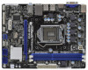
19 18 17 16 15 14 13 12 11 10 9 1 1155-Pin CPU Socket 2 ATX 12V Power Connector (ATX12V1) 3 CPU Fan Connector (CPU_FAN1) 4 ATX Power Connector (ATXPWR1) 5 2 x 240-pin DDR3 DIMM Slots (Dual Channel: DDR3_A1, DDR3_B1, Blue) 6 Intel H61 Chipset 7 32Mb SPI Flash 8 SATA2 Connector (SATA2_1, Blue - ASRock H61M-HVS | User Manual - Page 13
1.4 I/O Panel (H61M-HVGS) 1 2 3 4 5 11 10 9 1 PS/2 Mouse Port (Green) * 2 LAN RJ-45 Port 3 Line In (Light Blue) ** 4 Front Speaker (Lime) 5 Microphone (Pink) 6 USB 2.0 Ports (USB45) 8 7 6 7 USB 2.0 Ports (USB23) 8 USB 2.0 Ports (USB01) 9 VGA/HDMI Port 10 VGA/D-Sub Port 11 PS/2 Keyboard Port - ASRock H61M-HVS | User Manual - Page 14
1.5 I/O Panel (H61M-HVS) 1 11 10 9 1 PS/2 Mouse Port (Green) * 2 LAN RJ-45 Port 3 Line In (Light Blue) ** 4 Front Speaker (Lime) 5 Microphone (Pink) 6 USB 2.0 Ports (USB45) 2 3 4 5 8 7 6 7 USB 2.0 Ports (USB23) 8 USB 2.0 Ports (USB01) 9 VGA/HDMI Port 10 VGA/D-Sub Port 11 PS/2 Keyboard Port - ASRock H61M-HVS | User Manual - Page 15
Precautions Take note of the following precautions before you install motherboard components or change any motherboard settings. 1. Unplug the power cord from the wall socket before touching any component. 2. To avoid damaging the motherboard components due to static electricity, NEVER place your - ASRock H61M-HVS | User Manual - Page 16
Socket Body 1155-Pin Socket Overview Before you insert the 1155-Pin CPU into the socket, please check if the CPU surface is unclean or if there is any bent pin on the socket. Do not force to insert the CPU into the socket 2. This cap must be placed if returning the motherboard for after service. 16 - ASRock H61M-HVS | User Manual - Page 17
key Pin1 Pin1 orientation key notch 1155-Pin CPU alignment key 1155-Pin Socket For proper inserting, please ensure to match the two orientation key notches of the CPU with the two alignment keys of the socket. Step 3-3. Carefully place the CPU into the socket by using a purely vertical motion - ASRock H61M-HVS | User Manual - Page 18
operation or contact other components. Please be noticed that this motherboard supports Combo Cooler Option (C.C.O.), which provides the flexible option to adopt three different CPU cooler types, Socket LGA 775, LGA 1155 and LGA 1156. The white throughholes are for Socket LGA 1155/1156 CPU fan. 18 - ASRock H61M-HVS | User Manual - Page 19
2.5 Installation of Memory Modules (DIMM) This motherboard provides two 240-pin DDR3 (Double Data Rate 3) DIMM slots, and supports Dual Channel Memory Technology. For dual channel configuration, you always need to install two identical (the same brand, speed, size and chiptype) memory modules in - ASRock H61M-HVS | User Manual - Page 20
Express slots on this motherboard. PCIE slots: PCIE1 (PCIE x16 slot; Blue) is used for PCI Express x16 lane width graphics cards. PCIE2 (PCIE x1 slot; White) is used for PCI Express cards with x1 lane width cards, such as Gigabit LAN card, SATA2 card, etc. Installing an expansion card Step 1. Before - ASRock H61M-HVS | User Manual - Page 21
enjoy the benefits of dual monitor feature without installing any add-on VGA card to this motherboard. This motherboard also provides independent display controllers for HDMI and D-Sub to support dual VGA output so that HDMI and D-sub can drive same or different display contents. To enable dual - ASRock H61M-HVS | User Manual - Page 22
when the add-on VGA card is inserted to this motherboard. 4. Install the onboard VGA driver and the add-on PCI Express VGA card driver to your system. If you have installed the drivers already, there is no need to install them again. 5. Set up a multi-monitor display. For Windows® XP / XP 64-bit - ASRock H61M-HVS | User Manual - Page 23
Windows supported on this motherboard. To use HDCP function with this motherboard, you need to adopt the monitor that supports HDCP function as well. Therefore, you can enjoy the superior display quality with high-definition HDCP encryption contents. Please refer to below instruction compatible - ASRock H61M-HVS | User Manual - Page 24
to clear the CMOS when you just finish updating the BIOS, you must boot up the system first, and then shut it down before you do the clear-CMOS action. Please be noted that the password, date, time, user default profile, 1394 GUID and MAC address will be cleared only if the - ASRock H61M-HVS | User Manual - Page 25
and connectors will cause permanent damage of the motherboard! Serial ATAII Connectors (SATA2_0: see p.12, No. 10) (SATA2_1: see p.12, No. 8) on the I/O panel, there are two USB 2.0 headers on this motherboard. Each USB 2.0 header can support two USB 2.0 ports. Print Port Header (25-pin LPT1) (see - ASRock H61M-HVS | User Manual - Page 26
audio devices. 1. High Definition Audio supports Jack Sensing, but the panel wire on the chassis must support HDA to function correctly. Please follow the instruction in our manual and chassis manual on when the system is operating. The LED keeps blinking when the system is in S1 sleep state. The - ASRock H61M-HVS | User Manual - Page 27
to the ground pin. Though this motherboard provides 4-Pin CPU fan (Quiet Fan) support, the 3-Pin CPU fan still can work successfully even without the fan speed control function. If you plan to connect the 3-Pin CPU fan to the CPU fan connector on this motherboard, please connect it to Pin 1-3. Pin - ASRock H61M-HVS | User Manual - Page 28
ATX 12V Power Connector (4-pin ATX12V1) (see p.12 No. 2) Serial port Header (9-pin COM1) (see p.12 No. 17) Please connect an ATX 12V power supply to this connector. This COM1 header supports a serial port module. 28 - ASRock H61M-HVS | User Manual - Page 29
2.10 Serial ATA (SATA) / Serial ATAII (SATAII) Hard Disks Installation This motherboard adopts Intel® H61 chipset that supports Serial ATA (SATA) / Serial ATAII (SATAII) hard disks. You may install SATA / SATAII hard disks on this motherboard for internal storage devices. This section will guide you - ASRock H61M-HVS | User Manual - Page 30
is installed into system properly. The latest SATA / SATAII driver is available on our support website: www.asrock.com 4. Make sure to use the SATA power cable & data cable, which are from our motherboard package. 5. Please follow below instructions step by step to reduce the risk of HDD crash or - ASRock H61M-HVS | User Manual - Page 31
cable to (White) to the power supply 1x4-pin cable. the motherboard's SATAII connector. SATA power cable 1x4-pin power connector (White) Step attention, before you process the Hot Unplug: Please do follow below instruction sequence to process the Hot Unplug, improper procedure will cause the SATA - ASRock H61M-HVS | User Manual - Page 32
first. Then, the drivers compatible to your system can be auto-detected and listed on the support CD driver page. Please follow the order from up to bottom side to install those required drivers. Therefore, the drivers you install can work properly. 2.14 Installing Windows® 7 / 7 64-bit / VistaTM - ASRock H61M-HVS | User Manual - Page 33
on your system. At the beginning of Windows® setup, press F6 to install a third-party AHCI driver. When prompted, insert the SATA / SATAII driver diskette containing the Intel® AHCI driver. After reading the floppy disk, the driver will be presented. Select the driver to install according to the mode - ASRock H61M-HVS | User Manual - Page 34
configure your system. The UEFI chip on the motherboard stores the UEFI SETUP UTILITY. You may run the Because the UEFI software is constantly being updated, the following UEFI setup screens and descriptions /date information OC Tweaker To set up overclocking features Advanced To set up the advanced UEFI - ASRock H61M-HVS | User Manual - Page 35
Screen or exit the current screen 3.2 Main Screen When you enter the UEFI SETUP UTILITY, the Main screen will appear and display the system overview. H61M-HVGS 35 - ASRock H61M-HVS | User Manual - Page 36
H61M-HVS 36 - ASRock H61M-HVS | User Manual - Page 37
. Please note that overclocking may cause damage to your GPU and motherboard. It should be done at your own risk and expense. CPU Ratio Setting Use this item to change the ratio value of this motherboard. GT Over Clock Use this to enable or disable GT Over Clock by Internal Graphics Device. The - ASRock H61M-HVS | User Manual - Page 38
Turbo Boost power limit. Configuration options: [Auto] and [Manual]. The default value is [Auto]. Core Current Limit Use this item to add voltage when CPU is in Turbo mode. DRAM Timing Control DRAM Frequency If [Auto] is selected, the motherboard will detect the memory module(s) inserted and assigns - ASRock H61M-HVS | User Manual - Page 39
(tFAW) Use this item to change Four Activate Window (tFAW) Auto/Manual setting. The default is [Auto]. Memory Power Down PCH Voltage Use this to select PCH Voltage. The default value is [Auto]. CPU PLL Voltage Use this to select CPU PLL Voltage. The default value is [Auto]. VTT Voltage Use this to - ASRock H61M-HVS | User Manual - Page 40
configurations for the following items: CPU Configuration, North Bridge Configuration ASRock Instant Flash ASRock Instant Flash is a UEFI flash utility embedded in Flash ROM. This convenient UEFI update tool allows you to update system UEFI without entering operating systems first like MS-DOS or Windows - ASRock H61M-HVS | User Manual - Page 41
(C1). The C1 state is supported through the native processor instructions HLT and MWAIT and requires no hardware support from the chipset. In the C1 power state, the processor maintains the context of the system caches. CPU C3 State Support Use this to enable or disable CPU C3 (ACPI C2) report to - ASRock H61M-HVS | User Manual - Page 42
enhancement to the IA-32 Intel Architecture. An IA-32 processor with "No Execute (NX) Memory Protection" can prevent data pages from being used by malicious software to execute code. This option will be hidden if the current CPU does not support No-Excute Memory Protection. Local x2APIC Use this to - ASRock H61M-HVS | User Manual - Page 43
value is [DVMT Mode]. DVMT (Dynamic Video Memory Technology) is an architecture that offers breakthrough performance for the motherboard through efficient memory utilization. In DVMT mode, the graphics driver allocates memory as needed for running graphics applications and is cooperatively using this - ASRock H61M-HVS | User Manual - Page 44
DVMT Memory You are allowed to adjust the shared memory size in this item. Configuration options: [128MB], [256MB] and [Maximum]. The option [Maximum] only appears when you adopt the memory module with 1024MB or above. 44 - ASRock H61M-HVS | User Manual - Page 45
LAN" feature. Onboard HD Audio Select [Auto], [Enabled] or [Disabled] for the onboard HD Audio feature. If you select [Auto], the onboard HD Audio will be disabled when PCI Sound Card is plugged. Front Panel Select [Auto] or [Disabled] for the onboard HD Audio Front Panel. Onboard HDMI HD Audio - ASRock H61M-HVS | User Manual - Page 46
]. AHCI (Advanced Host Controller Interface) supports NCQ and other new features that will improve SATA disk performance but IDE mode does not have these advantages. SATA Controller 0 Please select [Compatible] when you install legacy OS. If native OS (Windows® XP / VistaTM / 7) is installed, please - ASRock H61M-HVS | User Manual - Page 47
3.4.5 Super IO Configuration Serial Port Use this item to enable or disable the onboard serial port. Serial Port Address Use this item to set the address for the onboard serial port. Configuration options: [3F8 / IRQ4] and [3E8 / IRQ4]. Parallel Port Use this item to enable or disable the onboard - ASRock H61M-HVS | User Manual - Page 48
3.4.6 ACPI Configuration Suspend to RAM Use this item to select whether to auto-detect or disable the Suspend-toRAM feature. Select [Auto] will enable this feature if the OS supports it. Check Ready Bit Use this item to enable or disable the feature Check Ready Bit. PS/2 Keyboard Power On Use this - ASRock H61M-HVS | User Manual - Page 49
for legacy USB. [Auto] - Enables legacy support if USB devices are connected. [Disabled] - USB devices are not allowed to use under legacy OS and UEFI setup when [Disabled] is selected. If you have USB compatibility issue, it is recommended to select [Disabled] to enter OS. [UEFI Setup Only] - USB - ASRock H61M-HVS | User Manual - Page 50
the status of the hardware on your system, including the parameters of the CPU temperature, motherboard temperature, CPU fan speed, chassis fan speed, and the critical voltage. CPU Fan Setting This allows you to set the CPU fan speed. Configuration options: [Full On] and [Automatic Mode]. The default - ASRock H61M-HVS | User Manual - Page 51
please select [Enabled]. Configuration options: [Enabled] and [Disabled]. The default value is [Enabled]. Boot From Onboard LAN Use this item to enable or disable the Boot From Onboard LAN feature. Boot Failure Guard Enable or disable the feature of Boot Failure Guard. Boot Failure Guard Count Enable - ASRock H61M-HVS | User Manual - Page 52
3.7 Security Screen In this section, you may set or change the supervisor/user password for the system. For the user password, you may also clear it. 52 - ASRock H61M-HVS | User Manual - Page 53
3.8 Exit Screen Save Changes and Exit When you select this option, it will pop-out the following message, "Save configuration changes and exit setup?" Select [OK] to save the changes and exit the UEFI SETUP UTILITY. Discard Changes and Exit When you select this option, it will pop-out the following - ASRock H61M-HVS | User Manual - Page 54
install the necessary drivers to activate the devices. 4.2.3 Utilities Menu The Utilities Menu shows the applications software that the motherboard supports. Click on a specific item then follow the installation wizard to install it. 4.2.4 Contact Information If you need to contact ASRock or want to - ASRock H61M-HVS | User Manual - Page 55
HDD Larger Than 2TB This motherboard is adopting UEFI BIOS that allows Windows® OS to be installed on a large size HDD (>2TB). Please follow below procedure to install the operating system. 1. Please make sure to use Windows® VistaTM 64-bit (with SP1 or above) or Windows® 7 64-bit. 2. Press or
-
 1
1 -
 2
2 -
 3
3 -
 4
4 -
 5
5 -
 6
6 -
 7
7 -
8
-
9
-
10
-
11
-
12
-
13
-
14
-
15
-
16
-
17
-
18
-
19
-
20
-
21
-
22
-
23
-
24
-
25
-
26
-
27
-
28
-
29
-
30
-
31
-
32
-
33
-
34
-
35
-
36
-
37
-
38
-
39
-
40
-
41
-
42
-
43
-
44
-
45
-
46
-
47
-
48
-
49
-
50
-
51
-
52
-
53
-
54
-
55
 |
 |

1
H61M-HVGS /
H61M-HVS
User Manual
Version 1.0
Published April 2011
Copyright©2011 ASRock INC. All rights reserved.