ASRock H61M-ITX User Manual
ASRock H61M-ITX Manual
 |
View all ASRock H61M-ITX manuals
Add to My Manuals
Save this manual to your list of manuals |
ASRock H61M-ITX manual content summary:
- ASRock H61M-ITX | User Manual - Page 1
H61M-ITX User Manual Version 1.0 Published May 2011 Copyright©2011 ASRock INC. All rights reserved. 1 - ASRock H61M-ITX | User Manual - Page 2
form or by any means, except duplication of documentation by the purchaser for backup purpose, without written consent of ASRock Inc. Products and corporate names appearing in this manual USA ONLY The Lithium battery adopted on this motherboard contains Perchlorate, a toxic substance controlled in - ASRock H61M-ITX | User Manual - Page 3
Plug Function for SATA / SATAII HDDs 28 2.13 SATA / SATAII HDD Hot Plug Feature and Operation Guide 29 2.14 Driver Installation Guide 31 2.15 Installing Windows® 7 / 7 64-bit / VistaTM / VistaTM 64-bit / XP / XP 64-bit Without RAID Functions 31 2.15.1 Installing Windows® XP / XP 64-bit Without - ASRock H61M-ITX | User Manual - Page 4
Screen 35 3.4 Advanced Screen 38 3.4.1 CPU Configuration 39 3.4.2 North Bridge Configuration 41 3.4.3 South Bridge Configuration 43 3.4.4 Storage Configuration 4 Software Support 52 4.1 Install Operating System 52 4.2 Support CD Information 52 4.2.1 Running Support CD 52 4.2.2 Drivers Menu 52 - ASRock H61M-ITX | User Manual - Page 5
fic information about the model you are using. www.asrock.com/support/index.asp 1.1 Package Contents ASRock H61M-ITX Motherboard (Mini-ITX Form Factor: 6.7-in x 6.7-in, 17.0 cm x 17.0 cm) ASRock H61M-ITX Quick Installation Guide ASRock H61M-ITX Support CD 2 x Serial ATA (SATA) Data Cables (Optional - ASRock H61M-ITX | User Manual - Page 6
- Mini-ITX Form Factor: 6.7-in x 6.7-in, 17.0 cm x 17.0 cm - All Solid Capacitor design (100% Japan-made high-quality Conductive Polymer Capacitors) - Supports 2nd Generation Intel® CoreTM i7 / i5 / i3 in LGA1155 Package - Supports Intel® Turbo Boost 2.0 Technology - Supports K-Series unlocked CPU - ASRock H61M-ITX | User Manual - Page 7
4 pin 12V power connector - Front panel audio connector - 2 x USB 2.0 headers (support 4 USB 2.0 ports) - 32Mb AMI BIOS - AMI UEFI Legal BIOS with GUI support - Supports "Plug and Play" - ACPI 1.1 Compliance Wake Up Events - Supports jumperfree - SMBIOS 2.3.1 Support - Drivers, Utilities, AntiVirus - ASRock H61M-ITX | User Manual - Page 8
ready power supply is required) (see CAUTION 15) * For detailed product information, please visit our website: http://www.asrock.com WARNING Please realize that there is a certain risk involved with overclocking, including adjusting the setting in the BIOS, applying Untied Overclocking Technology - ASRock H61M-ITX | User Manual - Page 9
motherboard supports Dual Channel Memory Technology. Before you implement Dual Channel Memory Technology, make sure to read the installation guide bit CPU, there is no such limitation. 4. The maximum shared memory size is defined by the chipset vendor and is subject to change. Please check Intel® - ASRock H61M-ITX | User Manual - Page 10
40% faster than before. ASRock APP Charger allows you to quickly charge many Apple devices simultaneously and even supports continuous charging when your PC enters into Standby mode (S1), Suspend to RAM (S3), hibernation mode (S4) or power off (S5). With APP Charger driver installed, you can easily - ASRock H61M-ITX | User Manual - Page 11
power consumption for the completed system. According to EuP, the total AC power of the completed system shall be under 1.00W in off mode condition. To meet EuP standard, an EuP ready motherboard and an EuP ready power supply are required. According to Intel's suggestion, the EuP ready power supply - ASRock H61M-ITX | User Manual - Page 12
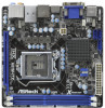
Keyboard 18 17 CPU_FAN1 32Mb BIOS Intel CIR1 USB6_7 USB8_9 9 H61 10 Fast USB X ATX12V1 H61M-ITX AUDIO CODEC PCIE1 11 HDMI 1.4a USB 3.0 Designed in Taipei RoHS 12 Top: LINE IN Center: FRONT Bottom: MIC IN 14 13 1 System Panel Header (PANEL1, White) 12 1155-Pin CPU Socket - ASRock H61M-ITX | User Manual - Page 13
1.4 I/O Panel 1 2 34 58 69 7 10 15 14 1 USB 2.0 Ports (USB01) 2 D-Sub Port 3 USB 2.0 Ports (USB23) * 4 LAN RJ-45 Port 5 Central / Bass (Orange) 6 Rear Speaker (Black) 7 Optical SPDIF Out Port 8 Line In (Light Blue) 13 12 11 ** 9 Front Speaker (Lime) 10 Microphone (Pink) 11 USB 3.0 Ports ( - ASRock H61M-ITX | User Manual - Page 14
This is a Mini-ITX form factor (6.7" x 6.7", 17.0 x 17.0 cm) motherboard. Before you install the motherboard, study the configuration of your chassis to ensure that the motherboard fits into it. Make sure to unplug the power cord before installing or removing the motherboard. Failure to do - ASRock H61M-ITX | User Manual - Page 15
Intel 1155-Pin CPU, please follow the steps below. Load Plate Load Lever Contact Array Socket Body 1155-Pin Socket Overview Before you insert the 1155-Pin CPU into the socket, please check if the CPU surface is unclean or if there is any bent pin on the socket motherboard for after service. 15 - ASRock H61M-ITX | User Manual - Page 16
key Pin1 Pin1 orientation key notch 1155-Pin CPU alignment key 1155-Pin Socket For proper inserting, please ensure to match the two orientation key notches of the CPU with the two alignment keys of the socket. Step 3-3. Carefully place the CPU into the socket by using a purely vertical motion - ASRock H61M-ITX | User Manual - Page 17
Heatsink This motherboard is equipped with 1155-Pin socket that supports Intel 1155-Pin CPU. Please adopt the type of heatsink and cooling fan compliant with Intel 1155Pin CPU to dissipate heat. Before you installed the heatsink, you need to spray thermal interface material between the CPU and the - ASRock H61M-ITX | User Manual - Page 18
Some DDR3 1GB double-sided DIMMs with 16 chips may not work on this motherboard. It is not recommended to install them on this motherboard. Installing a DIMM Please make sure to disconnect power supply before adding or removing DIMMs or the system components. Step 1. Step 2. Unlock a DIMM slot - ASRock H61M-ITX | User Manual - Page 19
make sure that the power supply is switched off or the power cord is unplugged. Please read the documentation of the expansion card and make necessary hardware settings for the card before you start the installation. Step 2. Remove the system unit cover (if your motherboard is already installed in - ASRock H61M-ITX | User Manual - Page 20
VGA card to this motherboard. This motherboard also provides independent display controllers for DVI-D, D-Sub and HDMI to support dual VGA output so port DVI-D port HDMI port 2. If you have installed onboard VGA driver from our support CD to your system already, you can freely enjoy the benefits - ASRock H61M-ITX | User Manual - Page 21
Display Feature This motherboard supports surround display upgrade. With the internal VGA output support (DVI-D, D-Sub is inserted to this motherboard. 4. Install the onboard VGA driver and the add-on PCI Express VGA card driver to your system. If you have installed the drivers already, there is - ASRock H61M-ITX | User Manual - Page 22
function is supported on this motherboard. To use HDCP function with this motherboard, you need to adopt the monitor that supports HDCP function as well. Therefore, you can enjoy the superior display quality with high-definition HDCP encryption contents. Please refer to below instruction for more - ASRock H61M-ITX | User Manual - Page 23
chassis on the market. 3. The Multi-Angle CIR Receiver does not support Hot-Plug function. Please install it before you boot the system. * ASRock Smart Remote is only supported by some of ASRock motherboards. Please refer to ASRock website for the motherboard support list: http://www.asrock.com 23 - ASRock H61M-ITX | User Manual - Page 24
power supply. After waiting for 15 seconds, use a jumper cap to short pin2 and pin3 on CLRCMOS1 for 5 seconds. However, please do not clear the CMOS right after you update the BIOS. If you need to clear the CMOS when you just finish updating the BIOS damage of the motherboard! Serial ATAII Connectors - ASRock H61M-ITX | User Manual - Page 25
9) 1 GND IRTX IRRX ATX+5VSB Besides four default USB 2.0 ports on the I/O panel, there are two USB 2.0 headers on this motherboard. Each USB 2.0 header can support two USB 2.0 ports. This header can be used to connect the remote controller receiver. Front Panel Audio Header (9-pin HD_AUDIO1) (see - ASRock H61M-ITX | User Manual - Page 26
but the panel wire on the chassis must support HDA to function correctly. Please follow the instruction in our manual and chassis manual to install your system. 2. If you The LED is off when the system is in S3/S4 sleep state or powered off (S5). HDLED (Hard Drive Activity LED): Connect to the hard - ASRock H61M-ITX | User Manual - Page 27
If you plan to connect the 3-Pin CPU fan to the CPU fan connector on this motherboard, please connect it to Pin 1-3. Pin 1-3 Connected 3-Pin Fan Installation ATX Power Connector 24 (24-pin ATXPWR1) (see p.12 No. 7) 12 13 Please connect an ATX power supply to this connector. 1 Though this - ASRock H61M-ITX | User Manual - Page 28
ATAII (SATAII) Hard Disks Installation This motherboard adopts Intel® H61 chipset that supports Serial ATA (SATA) / Serial ATAII (SATAII) hard disks. You may install SATA / SATAII hard disks on this motherboard for internal storage devices. This section will guide you to install the SATA / SATAII - ASRock H61M-ITX | User Manual - Page 29
is installed into system properly. The latest SATA / SATAII driver is available on our support website: www.asrock.com 4. Make sure to use the SATA power cable & data cable, which are from our motherboard package. 5. Please follow below instructions step by step to reduce the risk of HDD crash or - ASRock H61M-ITX | User Manual - Page 30
instruction sequence to process the Hot Plug, improper procedure will cause the SATA / SATAII HDD damage and data loss. Step 1 Please connect SATA power cable 1x4-pin end Step 2 Connect SATA data cable to (White) to the power supply 1x4-pin cable. the motherboard's SATAII connector. SATA power - ASRock H61M-ITX | User Manual - Page 31
and listed on the support CD driver page. Please follow the order from up to bottom side to install those required drivers. Therefore, the drivers you install can work properly. 2.15 Installing Windows® 7 / 7 64-bit / VistaTM / VistaTM 64-bit / XP / XP 64-bit Without RAID Functions If you want - ASRock H61M-ITX | User Manual - Page 32
driver. When prompted, insert the SATA / SATAII driver diskette containing the Intel® AHCI driver. After reading the floppy disk, the driver will be presented. Select the driver VistaTM 64-bit OS on your SATA / SATAII HDDs without RAID functions, please follow below steps. Using SATA / SATAII HDDs - ASRock H61M-ITX | User Manual - Page 33
system. The UEFI chip on the motherboard stores the UEFI SETUP UTILITY. You Power-On-Self-Test (POST) to enter the UEFI SETUP UTILITY, otherwise, POST will continue with its test software is constantly being updated, the following UEFI setup Tweaker To set up overclocking features Advanced To set - ASRock H61M-ITX | User Manual - Page 34
3.1.2 Navigation Keys Please check the following table for the function description of each navigation key. Navigation Key(s) Function Description / Moves cursor left or right to select Screens / Moves cursor up or down to select items + / - To change option for the selected items - ASRock H61M-ITX | User Manual - Page 35
overclocking features. CPU Control CPU Ratio Setting Use this item to change the ratio value of this motherboard CPU does not support Intel SpeedStep technology. Please note that enabling this function may reduce CPU voltage and lead to system stability or compatibility issue with some power supplies - ASRock H61M-ITX | User Manual - Page 36
Control DRAM Frequency If [Auto] is selected, the motherboard will detect the memory module(s) inserted and assigns appropriate frequency automatically for better compatibility. If you want the max performance for DDR3 1333 memory module(s), please manually adjust it to 1333. CAS# Latency (tCL) Use - ASRock H61M-ITX | User Manual - Page 37
Four Activate Window (tFAW) Use this item to change Four Activate Window (tFAW) Auto/Manual setting. The default is [Auto]. Memory Power Down Mode Use this item to adjust DDR power down mode. Configuration options: [Auto], [Slow] and [Fast]. The default value is [Auto]. Voltage Control DRAM Voltage - ASRock H61M-ITX | User Manual - Page 38
set the configurations for the following items: CPU Configuration, North Bridge Configuration, South Bridge Configuration, Storage Configuration, Super IO your USB flash drive, floppy disk or hard drive, then you can update your UEFI only in a few clicks without preparing an additional floppy diskette or - ASRock H61M-ITX | User Manual - Page 39
(C1). The C1 state is supported through the native processor instructions HLT and MWAIT and requires no hardware support from the chipset. In the C1 power state, the processor maintains the context of the system caches. CPU C3 State Support Use this to enable or disable CPU C3 (ACPI C2) report to - ASRock H61M-ITX | User Manual - Page 40
Architecture) can utilize the additional hardware capabilities provided by Vanderpool Technology. This option will be hidden if the installed CPU does not support Intel Virtualization Technology. No-Excute Memory Protection No-Execution (NX) Memory Protection Technology is an enhancement to the IA - ASRock H61M-ITX | User Manual - Page 41
Bridge Configuration Low MMIO Align Low MMIO resources align at 64MB/1024MB. The default value is [64MB]. VT-d Use this to enable or disable Intel® VT-d technology (Intel performance for the motherboard through efficient memory utilization. In DVMT mode, the graphics driver allocates memory as needed - ASRock H61M-ITX | User Manual - Page 42
DVMT Memory You are allowed to adjust the shared memory size in this item. Configuration options: [128MB], [256MB] and [Maximum]. The option [Maximum] only appears when you adopt the memory module with 1024MB or above. 42 - ASRock H61M-ITX | User Manual - Page 43
allows you to set the power state after an unexpected AC/power loss. If [Power Off] is selected, the AC/power remains off when the power recovers. If [Power On] is selected, the AC/power resumes and the system starts to boot up when the power recovers. Deep Sx Mobile platforms support Deep S4/S5 in - ASRock H61M-ITX | User Manual - Page 44
default value is [AHCI Mode]. AHCI (Advanced Host Controller Interface) supports NCQ and other new features that will improve SATA disk performance but / VistaTM / 7) is installed, please select [Enhanced]. SATA Aggressive Link Power Management This item appears only when you set "SATA Mode" to [AHCI - ASRock H61M-ITX | User Manual - Page 45
Hard Disk S.M.A.R.T. Use this item to enable or disable the S.M.A.R.T. (Self-Monitoring, Analysis, and Reporting Technology) feature. Configuration options: [Disabled] and [Enabled]. 3.4.5 Super IO Configuration CIR Controller Use this item to enable or disable CIR controller. 45 - ASRock H61M-ITX | User Manual - Page 46
-detect or disable the Suspend-toRAM feature. Select [Auto] will enable this feature if the OS supports it. Check Ready Bit Use this item to enable or disable the feature Check Ready Bit. PS/2 Keyboard Power On Use this item to enable or disable PS/2 keyboard to turn on the system from - ASRock H61M-ITX | User Manual - Page 47
to use only under UEFI setup and Windows / Linux OS. Legacy USB 3.0 Support Use this option to enable or disable legacy support for USB 3.0 devices. The default value is [Disabled]. To use Instant Flash, USB Keyboard/Remote Power On and USB Mouse Power On functions on USB 3.0 devices, please enable - ASRock H61M-ITX | User Manual - Page 48
the status of the hardware on your system, including the parameters of the CPU temperature, motherboard temperature, CPU fan speed, chassis fan speed, and the critical voltage. CPU Fan Setting This allows you to set the CPU fan speed. Configuration options: [Full On] and [Automatic Mode]. The default - ASRock H61M-ITX | User Manual - Page 49
3.6 Boot Screen In this section, it will display the available devices on your system for you to configure the boot settings and the boot priority. Setup Prompt Timeout This shows the number of seconds to wait for setup activation key. 65535(0XFFFF) means indefinite waiting. Bootup Num-Lock If this - ASRock H61M-ITX | User Manual - Page 50
3.7 Security Screen In this section, you may set or change the supervisor/user password for the system. For the user password, you may also clear it. 50 - ASRock H61M-ITX | User Manual - Page 51
3.8 Exit Screen Save Changes and Exit When you select this option, it will pop-out the following message, "Save configuration changes and exit setup?" Select [OK] to save the changes and exit the UEFI SETUP UTILITY. Discard Changes and Exit When you select this option, it will pop-out the following - ASRock H61M-ITX | User Manual - Page 52
install the necessary drivers to activate the devices. 4.2.3 Utilities Menu The Utilities Menu shows the applications software that the motherboard supports. Click on a specific item then follow the installation wizard to install it. 4.2.4 Contact Information If you need to contact ASRock or want to - ASRock H61M-ITX | User Manual - Page 53
Installing OS on a HDD Larger Than 2TB This motherboard is adopting UEFI BIOS that allows Windows® OS to be installed on a large install Windows® 7 64-bit OS, OS will be formatted by GPT (GUID Partition Table). Please install the hotfix file from Microsoft®: http://support.microsoft.com/kb/979903 53
-
 1
1 -
 2
2 -
 3
3 -
 4
4 -
 5
5 -
 6
6 -
 7
7 -
8
-
9
-
10
-
11
-
12
-
13
-
14
-
15
-
16
-
17
-
18
-
19
-
20
-
21
-
22
-
23
-
24
-
25
-
26
-
27
-
28
-
29
-
30
-
31
-
32
-
33
-
34
-
35
-
36
-
37
-
38
-
39
-
40
-
41
-
42
-
43
-
44
-
45
-
46
-
47
-
48
-
49
-
50
-
51
-
52
-
53
 |
 |

1
H61M-ITX
User Manual
Version 1.0
Published May 2011
Copyright©2011 ASRock INC. All rights reserved.