ASRock H61M-VS R2.0 Quick Installation Guide
ASRock H61M-VS R2.0 Manual
 |
View all ASRock H61M-VS R2.0 manuals
Add to My Manuals
Save this manual to your list of manuals |
ASRock H61M-VS R2.0 manual content summary:
- ASRock H61M-VS R2.0 | Quick Installation Guide - Page 1
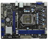
backup purpose, without written consent of ASRock Inc. Products and corporate names appearing in this guide may or may not be registered ASRock Website: http://www.asrock.com Published September 2011 Copyright©2011 ASRock INC. All rights reserved. 1 ASRock H61M-VGS R2.0 / H61M-VS R2.0 Motherboard - ASRock H61M-VS R2.0 | Quick Installation Guide - Page 2
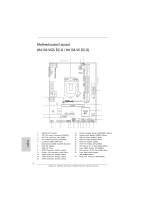
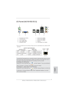
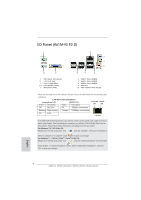
Header (LPT1, White) 19 PCI Express 2.0 x1 Slot (PCIE2, White) 20 Clear CMOS Jumper (CLRCMOS1) 21 PCI Express 2.0 x16 Slot (PCIE1, Blue) 22 Front Panel Audio Header (HD_AUDIO1, White) 23 Power Fan Connector (PWR_FAN1) 2 ASRock H61M-VGS R2.0 / H61M-VS R2.0 Motherboard English - ASRock H61M-VS R2.0 | Quick Installation Guide - Page 3
64-bit / VistaTM / VistaTM 64-bit OS: Please click "VIA HD Audio Deck" icon , and click "Advanced Options" on the left side on the bottom. In "Advanced Options" screen, select "Independent Headphone", and click "OK" to save your change. English 3 ASRock H61M-VGS R2.0 / H61M-VS R2.0 Motherboard - ASRock H61M-VS R2.0 | Quick Installation Guide - Page 4
64-bit / VistaTM / VistaTM 64-bit OS: Please click "VIA HD Audio Deck" icon , and click "Advanced Options" on the left side on the bottom. In "Advanced Options" screen, select "Independent Headphone", and click "OK" to save your change. English 4 ASRock H61M-VGS R2.0 / H61M-VS R2.0 Motherboard - ASRock H61M-VS R2.0 | Quick Installation Guide - Page 5
To get better performance in Windows® 7 / 7 64-bit / VistaTM / VistaTM 64bit, it is recommended to set the BIOS option in Storage Configuration to AHCI mode. For the BIOS setup, please refer to the "User Manual" in our support CD for details. 5 ASRock H61M-VGS R2.0 / H61M-VS R2.0 Motherboard English - ASRock H61M-VS R2.0 | Quick Installation Guide - Page 6
with Intel® Sandy Bridge CPU - Max. shared memory 1759MB (see CAUTION 4) - Supports D-Sub with max. resolution up to 2048x1536 @ 75Hz - 5.1 CH HD Audio (VIA® VT1705 Audio Codec) - H61M-VGS R2.0 Realtek PCIE x1 Gigabit LAN RTL8111E, speed 10/100/1000 Mb/s - H61M-VS R2.0 Realtek PCIE x1 LAN RTL8105E - ASRock H61M-VS R2.0 | Quick Installation Guide - Page 7
Monitor - Chassis Temperature Sensing - CPU/Chassis/Power Fan Tachometer - CPU/Chassis Quiet Fan (Allow Chassis Fan Speed Auto-Adjust by CPU Temperature) - CPU/Chassis Fan Multi-Speed Control - Voltage Monitoring: +12V, +5V, +3.3V, CPU Vcore 7 ASRock H61M-VGS R2.0 / H61M-VS R2.0 Motherboard - ASRock H61M-VS R2.0 | Quick Installation Guide - Page 8
output phases to improve efficiency when the CPU cores are idle without sacrificing computing performance. Please visit our website for the operation procedures of ASRock Extreme Tuning Utility (AXTU). ASRock website: http://www.asrock.com English 8 ASRock H61M-VGS R2.0 / H61M-VS R2.0 Motherboard - ASRock H61M-VS R2.0 | Quick Installation Guide - Page 9
check if the CPU fan on the motherboard functions properly and unplug the power cord, then plug it back again. To improve heat dissipation, remember to spray thermal grease between the CPU and the heatsink when you install the PC system. 9 ASRock H61M-VGS R2.0 / H61M-VS R2.0 Motherboard English - ASRock H61M-VS R2.0 | Quick Installation Guide - Page 10
CPU cooler types, Socket LGA 775, LGA 1155 and LGA 1156. Please be noticed that not all the 775 and 1156 CPU Fan standard, an EuP ready motherboard and an EuP ready power supply are required. According to Intel's suggestion, the EuP ready ASRock H61M-VGS R2.0 / H61M-VS R2.0 Motherboard English - ASRock H61M-VS R2.0 | Quick Installation Guide - Page 11
1155-Pin CPU into the socket, please check if the CPU surface is unclean or if there is any bent pin on the socket. Do not force to insert the CPU into the socket if above situation is found. Otherwise, the CPU will be seriously damaged. English 11 ASRock H61M-VGS R2.0 / H61M-VS R2.0 Motherboard - ASRock H61M-VS R2.0 | Quick Installation Guide - Page 12
orientation key notch alignment key Pin1 Pin1 orientation key notch 1155-Pin CPU alignment key 1155-Pin Socket For proper inserting, please ensure to match the two orientation key notches of the CPU with the two alignment keys of the socket. 12 ASRock H61M-VGS R2.0 / H61M-VS R2.0 Motherboard - ASRock H61M-VS R2.0 | Quick Installation Guide - Page 13
that this motherboard supports Combo Cooler Option (C.C.O.), which provides the flexible option to adopt three different CPU cooler types, Socket LGA 775, LGA 1155 and LGA 1156. The white throughholes are for Socket LGA 1155/1156 CPU fan. 13 ASRock H61M-VGS R2.0 / H61M-VS R2.0 Motherboard English - ASRock H61M-VS R2.0 | Quick Installation Guide - Page 14
damage to the motherboard and the DIMM if you force the DIMM into the slot at incorrect orientation. Step 3. Firmly insert the DIMM into the slot until the retaining clips at both ends fully snap back in place and the DIMM is properly seated. 14 ASRock H61M-VGS R2.0 / H61M-VS R2.0 Motherboard - ASRock H61M-VS R2.0 | Quick Installation Guide - Page 15
motherboard. PCIE slots: PCIE1 (PCIE x16 slot; Blue) is used for PCI Express x16 lane width graphics cards. PCIE2 (PCIE x1 slot; White) is used for PCI Express cards with x1 lane width cards, such as Gigabit LAN 6. Replace the system cover. 15 ASRock H61M-VGS R2.0 / H61M-VS R2.0 Motherboard English - ASRock H61M-VS R2.0 | Quick Installation Guide - Page 16
this motherboard. 4. Install the onboard VGA driver and the add-on PCI Express VGA card driver to your system. If you have installed the drivers already desktop onto this monitor". E. Right-click the display icon and select "Attached", if necessary. 16 ASRock H61M-VGS R2.0 / H61M-VS R2.0 Motherboard - ASRock H61M-VS R2.0 | Quick Installation Guide - Page 17
second monitor. Click "Apply" or "OK" to apply these new values. G. Repeat steps C through E for the diaplay icon identi bit / VistaTM / VistaTM 64-bit OS: Right click the desktop, choose "Personalize", and select the "Display Settings" tab so ASRock H61M-VGS R2.0 / H61M-VS R2.0 Motherboard English - ASRock H61M-VS R2.0 | Quick Installation Guide - Page 18
not clear the CMOS right after you update the BIOS. If you need to clear the CMOS when you just finish updating the BIOS, you must boot up the system first file, 1394 GUID and MAC address will be cleared only if the CMOS battery is removed. English 18 ASRock H61M-VGS R2.0 / H61M-VS R2.0 Motherboard - ASRock H61M-VS R2.0 | Quick Installation Guide - Page 19
SATA2_3: see p.2, No. 11) SATA2_3 SATA2_1 SATA2_2 SATA2_0 These four Serial ATAII (SATAII) connectors support SATA data cables for internal storage devices. The current SATAII interface allows up to 3.0 Gb/s connection of printer devices. English 19 ASRock H61M-VGS R2.0 / H61M-VS R2.0 Motherboard - ASRock H61M-VS R2.0 | Quick Installation Guide - Page 20
audio devices. 1. High Definition Audio supports Jack Sensing, but the panel wire on the chassis must support HDA to function correctly. Please follow the instruction in our manual and chassis manual hard drive is reading or writing data. 20 ASRock H61M-VGS R2.0 / H61M-VS R2.0 Motherboard English - ASRock H61M-VS R2.0 | Quick Installation Guide - Page 21
motherboard provides 4-Pin CPU fan (Quiet Fan) support, the 3-Pin CPU fan still can work successfully even without the fan speed control function. If you plan to connect the 3-Pin CPU fan to the CPU fan connector on this motherboard 1 13 21 ASRock H61M-VGS R2.0 / H61M-VS R2.0 Motherboard - ASRock H61M-VS R2.0 | Quick Installation Guide - Page 22
ATX 12V Power Connector (4-pin ATX12V1) (see p.2 No. 2) Serial port Header (9-pin COM1) (see p.2 No. 17) Please connect an ATX 12V power supply to this connector. This COM1 header supports a serial port module. English 22 ASRock H61M-VGS R2.0 / H61M-VS R2.0 Motherboard - ASRock H61M-VS R2.0 | Quick Installation Guide - Page 23
Driver Installation Guide To install the drivers to your system, please insert the support CD to your optical drive first. Then, the drivers compatible to your system can be auto-detected and listed on the support CD driver OS on your system. 23 ASRock H61M-VGS R2.0 / H61M-VS R2.0 Motherboard English - ASRock H61M-VS R2.0 | Quick Installation Guide - Page 24
screen SATA Configuration. B. Set the option "SATA Mode" to [IDE]. STEP 2: Install Windows® 7 / 7 64-bit / VistaTM / VistaTM 64-bit OS on your system. 24 ASRock H61M-VGS R2.0 / H61M-VS R2.0 Motherboard English - ASRock H61M-VS R2.0 | Quick Installation Guide - Page 25
information about BIOS Setup, please refer to the User Manual (PDF file) contained in the Support CD. 4. Software Support CD information This motherboard supports various Microsoft from the BIN folder in the Support CD to display the menus. 25 ASRock H61M-VGS R2.0 / H61M-VS R2.0 Motherboard English - ASRock H61M-VS R2.0 | Quick Installation Guide - Page 26
8.9 英吋 X 6.8 英吋 , 22.6 厘米 X 17.3 厘米 ) 華擎 H61M-VGS R2.0 / H61M-VS R2.0 H61M-VGS R2.0 / H61M-VS R2.0 Serial ATA(SATA I/O 擋板 ASRock 為了在 Windows® 7 / 7 64-bit / VistaTM / VistaTM 64-bit BIOS中將Storage Configuration AHCI BIOS User Manual 26 ASRock H61M-VGS R2.0 / H61M-VS R2.0 Motherboard 簡體中文 - ASRock H61M-VS R2.0 | Quick Installation Guide - Page 27
LAN RTL8105E, 速度 :10/100 Mb/s Wake-On-LAN) - 支持 PXE Rear Panel I/O 界面 I/O - 1 個 PS/2 1 個 PS/2 - 1 個 VGA 接口 - 6 USB 2.0 接口 - 1 個 RJ-45 LED 指示燈 (ACT/LINK LED 和 SPEED LED) 連接頭 - 4 x SATA2 3.0Gb/s NCQ, AHCI 能 - 1 x 27 ASRock H61M-VGS R2.0 / H61M-VS R2.0 Motherboard - ASRock H61M-VS R2.0 | Quick Installation Guide - Page 28
C.C.O 12) - CPU - CPU - CPU CPU 度) - CPU 12V, +5V, +3.3V 操作系統 - Microsoft® Windows® 7/7 64 位元 /VistaTM/VistaTM 64 位元 / XP/XP 64 認證 - FCC, CE, WHQL - 支持 ErP/EuP ErP/EuP 13) http://www.asrock.com 簡體中文 28 ASRock H61M-VGS R2.0 / H61M-VS R2.0 Motherboard - ASRock H61M-VS R2.0 | Quick Installation Guide - Page 29
ROM 的 BIOS BIOS MS-DOS 或 Windows B I O S F6> 鍵或在 B I O S F2 Instant Flash B I O S U B I O S U FAT32/64 7 i P h o n e / i P a d / i P o d touch APP Charger APP Charger iPhone 40%。華擎 APP Charger S1 S3 S4 S5 APP Charger 29 ASRock H61M-VGS R2.0 / H61M-VS R2.0 Motherboard 簡體中文 - ASRock H61M-VS R2.0 | Quick Installation Guide - Page 30
XFast USB USB 10、華擎 XFast LAN Youtube 11 CPU C P U PC CPU 12 C . C . O C P U L G A775, L G A1155 與 L G A1156 775 和 1156 CPU 13、EuP, 全稱 Energy Using Product E u P 1.00W EuP EuP EuP Intel EuP 100m A 5V s b 50 E u P 30 ASRock H61M-VGS R2.0 / H61M-VS R2.0 Motherboard 簡體中文 - ASRock H61M-VS R2.0 | Quick Installation Guide - Page 31
1.3 3 1 和針腳 2 CMOS (CLRCMOS1, 3 2 頁第 20 項 ) 設定 默認設置 清除 CMOS 注意: C L R C M O S1 C M O S 15 C L R C M O S1 2 和插針 3 短接 5 B I O S C M O S B I O S C M O S C M O S C M O S 1394 GUID 和 MAC 簡體中文 31 ASRock H61M-VGS R2.0 / H61M-VS R2.0 Motherboard - ASRock H61M-VS R2.0 | Quick Installation Guide - Page 32
ACK# SPD5 BUSY SPD4 PE SPD3 SLCT SPD2 SPD1 SPD0 STB# GND PRESENCE# MIC_RET OUT_RET 1 OUT2_L J_SENSE OUT2_R MIC2_R MIC2_L I/O USB 2.0 USB 2.0 USB 2.0 USB 2.0 接口。 32 ASRock H61M-VGS R2.0 / H61M-VS R2.0 Motherboard 簡體中文 - ASRock H61M-VS R2.0 | Quick Installation Guide - Page 33
1 High Definition Audio, HDA Jack Sensing HDA 2 AC'97 A. 將 Mic_IN(MIC) 連接到 MIC2_L。 B. 將 Audio_R(RIN) 連接到 OUT2_R, 將 Audio_L(LIN) 2 頁第 14 項 ) (4 針 SPEAKER1) ( 見第 2 頁第 13 項 ) PWRBTN RESET PLED S1 S3/S4 S5 HD LED 簡體中文 33 ASRock H61M-VGS R2.0 / H61M-VS R2.0 Motherboard - ASRock H61M-VS R2.0 | Quick Installation Guide - Page 34
項 ) CPU (4 針 CPU_FAN1) ( 見第 2 頁第 3 項 ) 4 3 2 1 GND +12V CPU_FAN_SPEED FAN_SPEED_CONTROL 請將 CPU 4-Pin CPU 風扇 (Quiet Fan 3-Pin CPU 3-Pin CPU CPU Pin 1-3。 (9 針 COM1) ( 見第 2 頁第 17 項 ) 20-Pin ATX 1 13 ATX 12V 這個 COM1 簡體中文 34 ASRock H61M-VGS R2.0 / H61M-VS R2.0 Motherboard - ASRock H61M-VS R2.0 | Quick Installation Guide - Page 35
2. BIOS 信息 Flash Memory 存儲了 BIOS POST F2> 或 < D e l B I O S P O S T P O S T B I O S Ctrl>++ - ASRock H61M-VS R2.0 | Quick Installation Guide - Page 36
SJ/T 11364-2006 10 年。 圖一 部件名稱 鉛 (Pb) 鎘 (Cd) 汞 (Hg Cr(VI PBB PBDE) X O O O O O X O O O O O O SJ/T 11363-2006 X SJ/T 11363-2006 2002/95/EC 簡體中文 36 ASRock H61M-VGS R2.0 / H61M-VS R2.0 Motherboard - ASRock H61M-VS R2.0 | Quick Installation Guide - Page 37
1 H61M-VGS R2.0 / H61M-VS R2.0 BIOS CPU http://www.asrock.com www.asrock.com/support/index.asp 1.1 華擎 H61M-VGS R2.0 / H61M-VS R2.0 主機板 (Micro ATX 規格 : 8.9 英吋 x 6.8 英吋 , 22.6 公分 x 17.3 公分 ) 華擎 H61M-VGS R2.0 / H61M-VS R2.0 H61M-VGS R2.0 / H61M-VS R2.0 Serial ATA(SATA I/O 擋板 ASRock - ASRock H61M-VS R2.0 | Quick Installation Guide - Page 38
x1 LAN RTL8105E, 速度 :10/100 Mb/s Wake-On-LAN) - 支援 PXE Rear Panel I/O 界面 I/O - 1 個 PS/2 1 個 PS/2 - 1 個 VGA 接口 - 6 USB 2.0 接口 - 1 個 RJ-45 LED 指示燈 (ACT/LINK LED 和 SPEED LED) 接頭 - 4 x SATA2 3.0Gb/s NCQ, AHCI - 1 x 38 ASRock H61M-VGS R2.0 / H61M-VS R2.0 Motherboard - ASRock H61M-VS R2.0 | Quick Installation Guide - Page 39
晚安 LED 指示燈 硬體監控 - CPU - CPU - CPU CPU 度) - CPU 12V, +5V, +3.3V 操作系統 - Microsoft® Windows® 7/7 64 位元 /VistaTM/VistaTM 64 位元 / XP/XP 64 位元 認證 - FCC, CE, WHQL - 支援 ErP/EuP ErP/EuP 13) http://www.asrock.com 繁體中文 39 ASRock H61M-VGS R2.0 / H61M-VS R2.0 Motherboard - ASRock H61M-VS R2.0 | Quick Installation Guide - Page 40
BIOS MS-DOS 或 Windows BIOS F6 BIOS F2 Instant Flash B I O S B I O S FAT32/64 7 W i i A I W I PC AIWI iPhone/ iPod touch PC A I W I App AIWI Lite 到您的 iPhone/iPod touch P C 和 A p p l e http://www.asrock.com/Feature/Aiwi/index.asp 40 ASRock H61M-VGS R2.0 / H61M-VS R2.0 Motherboard - ASRock H61M-VS R2.0 | Quick Installation Guide - Page 41
.asrock.com/Feature/SmartView/ index.asp 10、華擎 XFast USB 可提升 USB 11 C P U C P U PC CPU 12 C.C.O CPU LGA775,LGA1155 與 LGA1156 775 和 1156 CPU 13、EuP, 全稱 Energy Using Product EuP 1.00W EuP EuP EuP Intel EuP 100mA 5Vsb 50 EuP 41 ASRock H61M-VGS R2.0 / H61M-VS R2.0 Motherboard - ASRock H61M-VS R2.0 | Quick Installation Guide - Page 42
1.3 3 1 和針腳 2 CMOS (CLRCMOS1, 3 2 頁第 20 項 ) 設定 默認設置 清除 CMOS 註: C L R C M O S1 C M O S 15 CLRCMOS1 的 pin2 及 pin3 短路 5 BIOS CMOS BIOS CMOS CMOS C M O S 1394 GUID 及 MAC 繁體中文 42 ASRock H61M-VGS R2.0 / H61M-VS R2.0 Motherboard - ASRock H61M-VS R2.0 | Quick Installation Guide - Page 43
1 GND P+8 P-8 USB_PWR AFD# ERROR# PINIT# SLIN# GND 1 SPD7 SPD6 ACK# SPD5 BUSY SPD4 PE SPD3 SLCT SPD2 SPD1 SPD0 STB# I/O USB 2.0 USB 2.0 USB 2.0 USB 2.0 接口。 繁體中文 43 ASRock H61M-VGS R2.0 / H61M-VS R2.0 Motherboard - ASRock H61M-VS R2.0 | Quick Installation Guide - Page 44
項 ) GND PRESENCE# MIC_RET OUT_RET 1 OUT2_L J_SENSE OUT2_R MIC2_R MIC2_L 1 High Definition Audio, HDA Jack Sensing HDA 2 AC'97 A. 將 Mic_IN(MIC) 連接到 MIC2_L。 B. 見第 2 頁第 14 項 ) PWRBTN RESET PLED S1 S3/S4 S5 HD LED 44 ASRock H61M-VGS R2.0 / H61M-VS R2.0 Motherboard 繁體中文 - ASRock H61M-VS R2.0 | Quick Installation Guide - Page 45
CPU Pin 1-3。 Pin 1-3 連接 3-Pin ATX (24 針 ATXPWR1) ( 見第 2 頁第 4 項 ) 12 24 請將 ATX 1 13 24-pin ATX 12 24 20-pin ATX 20-pin ATX 著 Pin 1 和 Pin 13 ATX 12V (4 針 ATX12V1) ( 見第 2 頁第 2 項 ) 20-Pin ATX 1 13 ATX 12V 繁體中文 45 ASRock H61M-VGS R2.0 / H61M-VS R2.0 Motherboard - ASRock H61M-VS R2.0 | Quick Installation Guide - Page 46
針 COM1) ( 見第 2 頁第 17 項 ) COM1 2. BIOS 訊息 Flash Memory BIOS POST F2> 或 + + - ASRock H61M-VS R2.0 | Quick Installation Guide - Page 47
on a HDD Larger Than 2TB This motherboard is adopting UEFI BIOS that allows Windows® OS to be installed OS will be formatted by GPT (GUID Partition Table). Please install the hotfix file from Microsoft®: http://support.microsoft.com/kb/979903 47 ASRock H61M-VGS R2.0 / H61M-VS R2.0 Motherboard English
-
 1
1 -
 2
2 -
 3
3 -
 4
4 -
 5
5 -
 6
6 -
 7
7 -
8
-
9
-
10
-
11
-
12
-
13
-
14
-
15
-
16
-
17
-
18
-
19
-
20
-
21
-
22
-
23
-
24
-
25
-
26
-
27
-
28
-
29
-
30
-
31
-
32
-
33
-
34
-
35
-
36
-
37
-
38
-
39
-
40
-
41
-
42
-
43
-
44
-
45
-
46
-
47
 |
 |

1
ASRock
H61M-VGS R2.0 / H61M-VS R2.0
Motherboard
English
Copyright Notice:
No part of this installation guide may be reproduced, transcribed, transmitted, or trans-
lated in any language, in any form or by any means, except duplication of documentation
by the purchaser for backup purpose, without written consent of ASRock Inc.
Products and corporate names appearing in this guide may or may not be registered
trademarks or copyrights of their respective companies, and are used only for identi
fi
ca-
tion or explanation and to the owners’ bene
fi
t, without intent to infringe.
Disclaimer:
Speci
fi
cations and information contained in this guide are furnished for informational use
only and subject to change without notice, and should not be constructed as a commit-
ment by ASRock. ASRock assumes no responsibility for any errors or omissions that may
appear in this guide.
With respect to the contents of this guide, ASRock does not provide warranty of any kind,
either expressed or implied, including but not limited to the implied warranties or condi-
tions of merchantability or
fi
tness for a particular purpose. In no event shall ASRock, its
directors, of
fi
cers, employees, or agents be liable for any indirect, special, incidental, or
consequential damages (including damages for loss of pro
fi
ts, loss of business, loss of
data, interruption of business and the like), even if ASRock has been advised of the pos-
sibility of such damages arising from any defect or error in the guide or product.
This device complies with Part 15 of the FCC Rules. Operation is subject to the following
two conditions:
(1) this device may not cause harmful interference, and
(2) this device must accept any interference received, including interference that
may cause undesired operation.
CALIFORNIA, USA ONLY
The Lithium battery adopted on this motherboard contains Perchlorate, a toxic substance
controlled in Perchlorate Best Management Practices (BMP) regulations passed by the
California Legislature. When you discard the Lithium battery in California, USA, please
follow the related regulations in advance.
“Perchlorate Material-special handling may apply, see
www.dtsc.ca.gov/hazardouswaste/perchlorate”
ASRock Website: http://www.asrock.com
Published September 2011
Copyright
©
2011 ASRock INC. All rights reserved.