ASRock H67DE3 User Manual
ASRock H67DE3 Manual
 |
View all ASRock H67DE3 manuals
Add to My Manuals
Save this manual to your list of manuals |
ASRock H67DE3 manual content summary:
- ASRock H67DE3 | User Manual - Page 1
H67DE3 User Manual Version 1.0 Published November 2010 Copyright©2010 ASRock INC. All rights reserved. 1 - ASRock H67DE3 | User Manual - Page 2
purchaser for backup purpose, without written consent of ASRock Inc. Products and corporate names appearing in this manual may or may not be registered trademarks or copyrights , USA ONLY The Lithium battery adopted on this motherboard contains Perchlorate, a toxic substance controlled in Perchlorate - ASRock H67DE3 | User Manual - Page 3
Motherboard Layout 12 1.4 I/O Panel 13 2 Installation 15 2.1 Screw Holes 15 2.2 Pre-installation Precautions 15 2.3 CPU Installation 16 2.4 Installation of Heatsink and CPU Guide 33 2.15 Driver Installation Guide 35 2.16 Installing Windows® 7 / 7 64-bit / VistaTM / VistaTM 64-bit With RAID - ASRock H67DE3 | User Manual - Page 4
3.3 OC Tweaker Screen 39 3.4 Advanced Screen 42 3.4.1 CPU Con guration 43 3.4.2 Intel IGD SWSCI OpRegion Con guration........... 45 3.4.3 North Bridge Con 55 4 Software Support 56 4.1 Install Operating System 56 4.2 Support CD Information 56 4.2.1 Running Support CD 56 4.2.2 Drivers Menu 56 - ASRock H67DE3 | User Manual - Page 5
guide to BIOS setup and information of the Support CD. Because the motherboard speci cations and the BIOS software might be updated, the content of this manual will be subject to change without notice. In case any modi cations of this manual occur, the updated version will be available on ASRock - ASRock H67DE3 | User Manual - Page 6
- All Solid Capacitor design - Supports 2nd Generation Intel® CoreTM i7 / i5 / i3 in LGA1155 Package - Supports Intel® Turbo Boost 2.0 Technology - Supports K-Series unlocked CPU (see CAUTION 1) - Supports Hyper-Threading Technology (see CAUTION 2) - Intel® H67 - Dual Channel DDR3 Memory Technology - ASRock H67DE3 | User Manual - Page 7
x SATA2 3.0 Gb/s connectors, support RAID (RAID 0, RAID 1, RAID 10, RAID 5 and Intel Rapid Storage), NCQ, AHCI and Hot Plug functions - 2 x SATA3 6.0Gb/s connectors - 1 x IR header - 1 x CIR header - 1 x COM port header - 1 x HDMI_SPDIF header - 1 x Power LED header - CPU/Chassis/Power FAN connector - ASRock H67DE3 | User Manual - Page 8
SMBIOS 2.3.1 Support - IGPU, DRAM, PCH, CPU PLL, VTT, VCCSA Voltage Multi-adjustment Support CD - Drivers, Utilities, AntiVirus Software (Trial Version), ASRock Software Suite (CyberLink DVD Suite - OEM and Trial; Creative Sound Blaster X-Fi MB - Trial) Unique Feature - ASRock Extreme Tuning - ASRock H67DE3 | User Manual - Page 9
the CPU cores are idle without sacrificing computing performance. Please visit our website for the operation procedures of ASRock Extreme Tuning Utility (AXTU). ASRock website: http://www.asrock.com 10. ASRock Instant Flash is a BIOS ash utility embedded in Flash ROM. This convenient BIOS update - ASRock H67DE3 | User Manual - Page 10
ASRock Instant Flash. Just launch this tool and save the new BIOS le to your USB ash drive, oppy disk or hard drive, then you can update your BIOS is just to install the ASRock AIWI utility either from ASRock of cial website or ASRock software support CD to your motherboard, and also download the - ASRock H67DE3 | User Manual - Page 11
adopt three different CPU cooler types, Socket LGA 775, LGA 1155 and LGA 1156. Please be noticed that not all the 775 and 1156 CPU Fan can be used To meet EuP standard, an EuP ready motherboard and an EuP ready power supply are required. According to Intel's suggestion, the EuP ready power supply - ASRock H67DE3 | User Manual - Page 12
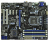
PHY H67DE3 7 8 32 PCIE1 PCI Express 2.0 CMOS ErP/EuP Ready 31 PCIE2 Battery USB 3.0 30 Super I/O PCIE3 Intel 9 H67 SPI Flash 2 ATX 12V Power Connector (ATX12V1) 20 Clear CMOS Jumper (CLRCMOS1) 3 1155-Pin CPU Socket 21 USB 2.0 Header (USB8_9, Blue) 4 2 x 240-pin DDR3 DIMM Slots - ASRock H67DE3 | User Manual - Page 13
(Light Blue) 3 47 58 69 12 11 10 ** 8 9 10 11 12 13 14 Front Speaker (Lime) Microphone (Pink) USB 2.0 Ports (USB45) USB 3.0 Ports (USB3_0_1) VGA/HDMI Port VGA/DVI-D Port PS/2 Keyboard Port (Purple) * There are two LED next to the LAN port. Please refer to the table below for the - ASRock H67DE3 | User Manual - Page 14
To enable Multi-Streaming function, you need to connect a front panel audio cable to the front panel audio header. After restarting your computer, you will nd "Mixer" tool on your system. Please select "Mixer ToolBox" , click "Enable playback multi-streaming", and click "ok". Choose "2CH", "4CH - ASRock H67DE3 | User Manual - Page 15
Precautions Take note of the following precautions before you install motherboard components or change any motherboard settings. 1. Unplug the power cord from the wall socket before touching any component. 2. To avoid damaging the motherboard components due to static electricity, NEVER place your - ASRock H67DE3 | User Manual - Page 16
Intel 1155-Pin CPU, please follow the steps below. Load Plate Load Lever Contact Array Socket Body 1155-Pin Socket Overview Before you insert the 1155-Pin CPU into the socket, please check if the CPU surface is unclean or if there is any bent pin on the socket motherboard for after service. 16 - ASRock H67DE3 | User Manual - Page 17
key Pin1 Pin1 orientation key notch 1155-Pin CPU alignment key 1155-Pin Socket For proper inserting, please ensure to match the two orientation key notches of the CPU with the two alignment keys of the socket. Step 3-3. Carefully place the CPU into the socket by using a purely vertical motion - ASRock H67DE3 | User Manual - Page 18
Heatsink This motherboard is equipped with 1155-Pin socket that supports Intel 1155-Pin CPU. Please adopt the type of heatsink and cooling fan compliant with Intel 1155Pin CPU to dissipate heat. Before you installed the heatsink, you need to spray thermal interface material between the CPU and the - ASRock H67DE3 | User Manual - Page 19
Memory Modules (DIMM) This motherboard provides four 240-pin DDR3 (Double Data Rate 3) DIMM slots, and supports Dual Channel Memory Technology. module or three memory modules are installed in the DDR3 DIMM slots on this motherboard, it is unable to activate the Dual Channel Memory Technology. 3. If a - ASRock H67DE3 | User Manual - Page 20
matches the break on the slot. notch break notch break The DIMM only ts in one correct orientation. It will cause permanent damage to the motherboard and the DIMM if you force the DIMM into the slot at incorrect orientation. Step 3. Firmly insert the DIMM into the slot until the retaining - ASRock H67DE3 | User Manual - Page 21
of the expansion card and make necessary hardware settings for the card before you start the installation. Remove the system unit cover (if your motherboard is already installed in a chassis). Remove the bracket facing the slot that you intend to use. Keep the screws for later use. Align the - ASRock H67DE3 | User Manual - Page 22
of dual monitor feature without installing any add-on VGA card to this motherboard. This motherboard also provides independent display controllers for DVI-D, D-Sub and HDMI to support dual VGA output so that DVI-D, D-sub and HDMI can drive same or different display contents. To enable dual monitor - ASRock H67DE3 | User Manual - Page 23
memory. If you do not adjust the BIOS setup, the default value of "Onboard VGA Share Memory", [Auto], will disable VGA/D-Sub function when the add-on VGA card is inserted to this motherboard. 4. Install the onboard VGA driver and the add-on PCI Express VGA card driver to your system. If you have - ASRock H67DE3 | User Manual - Page 24
function is supported on this motherboard. To use HDCP function with this motherboard, you need to adopt the monitor that supports HDCP function as well. Therefore, you can enjoy the superior display quality with high-de nition HDCP encryption contents. Please refer to below instruction for more - ASRock H67DE3 | User Manual - Page 25
need to clear the CMOS when you just nish updating the BIOS, you must boot up the system rst, and then shut it down before you do the clear-CMOS action. Please be noted that the password, date, time, user default pro le, 1394 GUID and MAC address will be cleared only if - ASRock H67DE3 | User Manual - Page 26
disk or the SATAII / SATA3 connector on this motherboard. Besides four default USB 2.0 ports on the I/O panel, there are two USB 2.0 headers on this motherboard. Each USB 2.0 header can support two USB 2.0 ports. This header supports an optional wireless transmitting and receiving infrared module. - ASRock H67DE3 | User Manual - Page 27
allows convenient connection and control of audio devices. 1. High Definition Audio supports Jack Sensing, but the panel wire on the chassis must support HDA to function correctly. Please follow the instruction in our manual and chassis manual to install your system. 2. If you use AC'97 audio panel - ASRock H67DE3 | User Manual - Page 28
PLED (System Power LED): Connect to the power status indicator on the chassis front panel. The LED is on when the system is operating. The LED keeps blinking when the system is in S1 sleep state. The LED is off when the system is in S3/S4 sleep state or powered off (S5). HDLED (Hard Drive Activity - ASRock H67DE3 | User Manual - Page 29
to the ground pin. Though this motherboard provides 4-Pin CPU fan (Quiet Fan) support, the 3-Pin CPU fan still can work successfully even without the fan speed control function. If you plan to connect the 3-Pin CPU fan to the CPU fan connector on this motherboard, please connect it to Pin 1-3. Pin - ASRock H67DE3 | User Manual - Page 30
HDMI_SPDIF Header (2-pin HDMI_SPDIF1) (see p.12 No. 27) 1 GND SPDIFOUT This COM1 header supports a serial port module. HDMI_SPDIF header, providing SPDIF audio output to HDMI VGA card, allows the system to connect HDMI Digital TV/ projector/LCD devices. Please connect the HDMI_SPDIF connector of - ASRock H67DE3 | User Manual - Page 31
Disks Installation This motherboard adopts Intel® H67 chipset that supports Serial ATA3 (SATA3) hard disks and RAID (RAID 0, RAID 1, RAID 10, RAID 5 and Intel Rapid Storage) functions. You may install SATA3 hard disks on this motherboard for internal storage devices. This section will guide you to - ASRock H67DE3 | User Manual - Page 32
and in working condition. 2.13 Hot Plug and Hot Swap Functions for SATA3 HDDs This motherboard supports Hot Plug and Hot Swap functions for SATA3 in RAID / AHCI mode. Intel® H67 chipset provides hardware support for Advanced Host controller Interface (AHCI), a new programming interface for SATA host - ASRock H67DE3 | User Manual - Page 33
installed into system properly. The latest SATA / SATAII / SATA3 driver is available on our support website: www.asrock.com 4. Make sure to use the SATA power cable & data cable, which are from our motherboard package. 5. Please follow below instructions step by step to reduce the risk of HDD crash - ASRock H67DE3 | User Manual - Page 34
cable to (White) to the power supply 1x4-pin cable. the motherboard's SATAII / SATA3 connector. SATA power cable 1x4-pin power connector ( of attention, before you process the Hot Unplug: Please do follow below instruction sequence to process the Hot Unplug, improper procedure will cause the SATA - ASRock H67DE3 | User Manual - Page 35
\ RAID Installation Guide and the document in the support CD, "Guide to Intel Rapid Storage", which is located in the folder at the following path: .. \ Intel Rapid Storage Information If you want to use "Intel Rapid Storage" in Windows® environment, please install "SATAII driver" from the Support - ASRock H67DE3 | User Manual - Page 36
OS on your SATA / SATAII / SATA3 HDDs without RAID functions, please follow below steps. AHCI mode is not supported under Windows® XP / XP 64-bit OS. Using SATA / SATAII / SATA3 HDDs without NCQ function STEP 1: Set up BIOS. A. Enter BIOS SETUP UTILITY Advanced screen SATA Con guration. B. Set the - ASRock H67DE3 | User Manual - Page 37
system. The UEFI chip on the motherboard stores the UEFI SETUP UTILITY. You -Test (POST) to enter the UEFI SETUP UTILITY, otherwise, POST will continue with its test software is constantly being updated, the following UEFI setup screens OC Tweaker To set up overclocking features Advanced To set up - ASRock H67DE3 | User Manual - Page 38
3.1.2 Navigation Keys Please check the following table for the function description of each navigation key. Navigation Key(s) Function Description / / + / Moves cursor left or right to select Screens Moves cursor up or down to select items To change option for the - ASRock H67DE3 | User Manual - Page 39
the OC Tweaker screen, you can set up overclocking features. Load GPU EZ OC Setting Use this item to load GPU EZ overclocking setting. Please note that overclocking may cause damage to your GPU and motherboard. It should be done at your own risk and expense. CPU Ratio Setting Use this item to change - ASRock H67DE3 | User Manual - Page 40
Turbo Boost power limit. Con guration options: [Auto] and [Manual]. The default value is [Auto]. Core Current Limit Use this item to add voltage when CPU is in Turbo mode. DRAM Timing Control DRAM Frequency If [Auto] is selected, the motherboard will detect the memory module(s) inserted and assigns - ASRock H67DE3 | User Manual - Page 41
Use this item to change Four Activate Window (tFAW) Auto/Manual setting. The default is [Auto]. Memory Power Down Mode Use options: [Auto], [0.780V] to [1.646V]. The default value is [Auto]. CPU PLL Voltage Use this to select CPU PLL Voltage. Con guration options: [Auto], [1.548V] to [2.310V]. The - ASRock H67DE3 | User Manual - Page 42
you may set the con gurations for the following items: CPU Con guration, Intel IGD SWSCI OpRegion Con guration, North Bridge Con guration, malfunction. ASRock Instant Flash ASRock Instant Flash is a UEFI flash utility embedded in Flash ROM. This convenient UEFI update tool allows you to update system - ASRock H67DE3 | User Manual - Page 43
(C1). The C1 state is supported through the native processor instructions HLT and MWAIT and requires no hardware support from the chipset. In the C1 power state, the processor maintains the context of the system caches. CPU C3 State Support Use this to enable or disable CPU C3 (ACPI C2) report to - ASRock H67DE3 | User Manual - Page 44
Architecture) can utilize the additional hardware capabilities provided by Vanderpool Technology. This option will be hidden if the installed CPU does not support Intel Virtualization Technology. No-Excute Memory Protection No-Execution (NX) Memory Protection Technology is an enhancement to the IA - ASRock H67DE3 | User Manual - Page 45
Mode]. DVMT (Dynamic Video Memory Technology) is an architecture that offers breakthrough performance for the motherboard through ef cient memory utilization. In DVMT mode, the graphics driver allocates memory as needed for running graphics applications and is cooperatively using this memory with - ASRock H67DE3 | User Manual - Page 46
Bridge Configuration Low MMIO Align Low MMIO resources align at 64MB/1024MB. The default value is [64MB]. VT-d Use this to enable or disable Intel® VT-d technology (Intel® Virtualization Technology for Directed I/O). The default value of this feature is [Disabled]. Primary Graphics Adapter This - ASRock H67DE3 | User Manual - Page 47
. Deep Sx Mobile platforms support Deep S4/S5 in DC only and desktop platforms support Deep S4/S5 in AC HDMI HD Audio" feature. ACPI HPET Table Use this item to enable or disable ACPI HPET Table. The default value is [Enabled]. Please set this option to [Enabled] if you plan to use this motherboard - ASRock H67DE3 | User Manual - Page 48
Configuration SATA Mode Use this to select SATA mode. Con guration options: [IDE Mode], [AHCI Mode] and [RAID Mode]. The default value is [IDE Mode]. AHCI (Advanced Host Controller Interface) supports NCQ and other new features that will improve SATA disk performance but IDE mode does not have these - ASRock H67DE3 | User Manual - Page 49
3.4.6 Super IO Configuration Serial Port Use this item to enable or disable the onboard serial port. Serial Port Address Use this item to set the address for the onboard serial port. Con guration options: [Auto], [3F8 / IRQ4], [2F8 / IRQ3], [3E8 / IRQ4], [2E8 / IRQ3]. Infrared Port Use this item to - ASRock H67DE3 | User Manual - Page 50
RAM Use this item to select whether to auto-detect or disable the Suspend-toRAM feature. Select [Auto] will enable this feature if the OS supports it. Check Ready Bit Use this item to enable or disable the feature Check Ready Bit. PS/2 Keyboard Power On Use this item to enable - ASRock H67DE3 | User Manual - Page 51
issue, it is recommended to select [Disabled] to enter OS. [UEFI Setup Only] - USB devices are allowed to use only under UEFI setup and Windows / Linux OS. Legacy USB 3.0 Support Use this option to enable or disable legacy support for USB 3.0 devices. The default value is [Enabled]. 51 - ASRock H67DE3 | User Manual - Page 52
CPU temperature, motherboard temperature, CPU fan speed, chassis fan speed, and the critical voltage. CPU Fan 1 & 2 Setting This allows you to set the CPU the chassis fan 3 speed. Con guration options: [Full On] and [Manual Mode]. The default is value [Full On]. Over Temperature Protection Use this - ASRock H67DE3 | User Manual - Page 53
3.6 Boot Screen In this section, it will display the available devices on your system for you to con gure the boot settings and the boot priority. Setup Prompt Timeout This shows the number of seconds to wait for setup activation key. 65535(0XFFFF) means inde nite waiting. Bootup Num-Lock If this - ASRock H67DE3 | User Manual - Page 54
3.7 Security Screen In this section, you may set or change the supervisor/user password for the system. For the user password, you may also clear it. 54 - ASRock H67DE3 | User Manual - Page 55
3.8 Exit Screen Save Changes and Exit When you select this option, it will pop-out the following message, "Save con guration changes and exit setup?" Select [OK] to save the changes and exit the UEFI SETUP UTILITY. Discard Changes and Exit When you select this option, it will pop-out the following - ASRock H67DE3 | User Manual - Page 56
install the necessary drivers to activate the devices. 4.2.3 Utilities Menu The Utilities Menu shows the applications software that the motherboard supports. Click on a speci c item then follow the installation wizard to install it. 4.2.4 Contact Information If you need to contact ASRock or want to - ASRock H67DE3 | User Manual - Page 57
Installing OS on a HDD Larger Than 2TB This motherboard is adopting UEFI BIOS that allows Windows® OS to be installed on a large install Windows® 7 64-bit OS, OS will be formatted by GPT (GUID Partition Table). Please install the hotfix file from Microsoft®: http://support.microsoft.com/kb/979903 57
-
 1
1 -
 2
2 -
 3
3 -
 4
4 -
 5
5 -
 6
6 -
 7
7 -
8
-
9
-
10
-
11
-
12
-
13
-
14
-
15
-
16
-
17
-
18
-
19
-
20
-
21
-
22
-
23
-
24
-
25
-
26
-
27
-
28
-
29
-
30
-
31
-
32
-
33
-
34
-
35
-
36
-
37
-
38
-
39
-
40
-
41
-
42
-
43
-
44
-
45
-
46
-
47
-
48
-
49
-
50
-
51
-
52
-
53
-
54
-
55
-
56
-
57
 |
 |

1
H67DE3
User Manual
Version 1.0
Published November 2010
Copyright©2010 ASRock INC. All rights reserved.