ASRock H67M-ITX Quick Installation Guide
ASRock H67M-ITX Manual
 |
View all ASRock H67M-ITX manuals
Add to My Manuals
Save this manual to your list of manuals |
ASRock H67M-ITX manual content summary:
- ASRock H67M-ITX | Quick Installation Guide - Page 1
backup purpose, without written consent of ASRock Inc. Products and corporate names appearing in this guide may or may not be registered trademarks ASRock Website: http://www.asrock.com Published January 2011 Copyright©2011 ASRock INC. All rights reserved. 1 ASRock H67M-ITX/HT / H67M-ITX Motherboard - ASRock H67M-ITX | Quick Installation Guide - Page 2
10 COM Port Header (COM1) 21 Intel H67 Chipset 11 ATX Power Connector (ATXPWR1) 22 64Mb SPI Flash 12 Chassis Speaker Header (SPEAKER 1, White) 23 CPU Fan Connector (CPU_FAN1) 13 Mini PCI Express Slot (MINI_PCIE1) 24 Power LED Header (PLED1) English 2 ASRock H67M-ITX/HT / H67M-ITX Motherboard - ASRock H67M-ITX | Quick Installation Guide - Page 3
Consumer Infrared Module Header (CIR1) 19 Intel H67 Chipset 10 COM Port Header (COM1) 20 64Mb SPI Flash 11 ATX Power Connector (ATXPWR1) 21 CPU Fan Connector (CPU_FAN1) 12 Chassis Speaker Header (SPEAKER 1, White) 22 Power LED Header (PLED1) English 3 ASRock H67M-ITX/HT / H67M-ITX Motherboard - ASRock H67M-ITX | Quick Installation Guide - Page 4
"Realtek HDA Primary output" to use Rear Speaker, Central/Bass, and Front Speaker, or select "Realtek HDA Audio 2nd output" to use front panel audio. 4 ASRock H67M-ITX/HT / H67M-ITX Motherboard English - ASRock H67M-ITX | Quick Installation Guide - Page 5
"Realtek HDA Primary output" to use Rear Speaker, Central/Bass, and Front Speaker, or select "Realtek HDA Audio 2nd output" to use front panel audio. 5 ASRock H67M-ITX/HT / H67M-ITX Motherboard English - ASRock H67M-ITX | Quick Installation Guide - Page 6
Controller (H67M-ITX/HT) H67M-ITX/HT is bundled with one Remote Receiver and one Remote Controller. You can enjoy more of your favorite entertainment by MCE (Media Center Edition) Remote Controller. The MCE features the entertainment center which allows you to enjoy a more convenient way of power on - ASRock H67M-ITX | Quick Installation Guide - Page 7
. Therefore, from anywhere within the signal range, you will be able to play LAN games, connect to the internet, access and share printers, and make Internet phone calls easily. Antenna Ports WiFi-802.11n Module ASRock WiFi 2.4GHz Antenna English 7 ASRock H67M-ITX/HT / H67M-ITX Motherboard - ASRock H67M-ITX | Quick Installation Guide - Page 8
WiFi-802.11n module supports Station mode. You can use the wireless function to connect the access point (AP), or connect PC, notebook and other devices for wireless communication. * The transmission speed may vary according to the environment. 8 ASRock H67M-ITX/HT / H67M-ITX Motherboard English - ASRock H67M-ITX | Quick Installation Guide - Page 9
/ H67M-ITX Motherboard (Mini-ITX Form Factor: 6.7-in x 6.7-in, 17.0 cm x 17.0 cm) ASRock H67M-ITX/HT / H67M-ITX Quick Installation Guide ASRock H67M-ITX/HT / H67M-ITX Support CD 2 x Serial ATA (SATA) Data Cables (Optional) 1 x I/O Panel Shield 1 x 3D Red/Cyan Anaglyph Glasses (Optional) 1 x Remote - ASRock H67M-ITX | Quick Installation Guide - Page 10
and HDMI ports - Supports Full HD 1080p Blu-ray (BD) / HD-DVD playback with DVI and HDMI ports - 7.1 CH HD Audio with Content Protection (Realtek ALC892 Audio Codec) - Premium Blu-ray audio support - Supports THX TruStudio PROTM (H67M-ITX/HT) 10 ASRock H67M-ITX/HT / H67M-ITX Motherboard English - ASRock H67M-ITX | Quick Installation Guide - Page 11
6.0Gb/s connectors - 1 x CIR header - 1 x COM port header - 1 x Power LED header - CPU/Chassis FAN connector - 24 pin ATX power connector - 4 pin 12V power connector - Front panel audio connector - 2 x USB 2.0 headers (support 4 USB 2.0 ports) English 11 ASRock H67M-ITX/HT / H67M-ITX Motherboard - ASRock H67M-ITX | Quick Installation Guide - Page 12
tools. Overclocking may affect your system stability, or even cause damage to the components and devices of your system. It should be done at your own risk and expense. We are not responsible for possible damage caused by overclocking. English 12 ASRock H67M-ITX/HT / H67M-ITX Motherboard - ASRock H67M-ITX | Quick Installation Guide - Page 13
of output phases to improve efficiency when the CPU cores are idle without sacrificing computing performance. Please visit our website for the operation procedures of ASRock Extreme Tuning Utility (AXTU). ASRock website: http://www.asrock.com 13 ASRock H67M-ITX/HT / H67M-ITX Motherboard English - ASRock H67M-ITX | Quick Installation Guide - Page 14
BIOS setup menu to access ASRock Instant Flash. Just launch this tool and save the new BIOS file to your USB flash drive, floppy disk or hard drive, then you can update your BIOS IE8. ASRock website: http://www.asrock.com/Feature/ SmartView/index.asp 14 ASRock H67M-ITX/HT / H67M-ITX Motherboard English - ASRock H67M-ITX | Quick Installation Guide - Page 15
Intel's suggestion, the EuP ready power supply must meet the standard of 5v standby power efficiency is higher than 50% under 100 mA current consumption. For EuP ready power supply selection, we recommend you checking with the power supply manufacturer for more details. 15 ASRock H67M-ITX/HT / H67M - ASRock H67M-ITX | Quick Installation Guide - Page 16
the 1155-Pin CPU into the socket, please check if the CPU surface is unclean or if there is any bent pin on the socket. Do not force to insert the CPU into the socket if above situation is found. Otherwise, the CPU will be seriously damaged. English 16 ASRock H67M-ITX/HT / H67M-ITX Motherboard - ASRock H67M-ITX | Quick Installation Guide - Page 17
key notch alignment key Pin1 Pin1 orientation key notch 1155-Pin CPU alignment key 1155-Pin Socket For proper inserting, please ensure to match the two orientation key notches of the CPU with the two alignment keys of the socket. 17 ASRock H67M-ITX/HT / H67M-ITX Motherboard English - ASRock H67M-ITX | Quick Installation Guide - Page 18
cannot be secured on the motherboard. Step 5. Step 6. Connect fan header with the CPU fan connector on the motherboard. Secure excess cable with tie-wrap to ensure cable does not interfere with fan operation or contact other components. English 18 ASRock H67M-ITX/HT / H67M-ITX Motherboard - ASRock H67M-ITX | Quick Installation Guide - Page 19
damage to the motherboard and the DIMM if you force the DIMM into the slot at incorrect orientation. Step 3. Firmly insert the DIMM into the slot until the retaining clips at both ends fully snap back in place and the DIMM is properly seated. 19 ASRock H67M-ITX/HT / H67M-ITX Motherboard English - ASRock H67M-ITX | Quick Installation Guide - Page 20
(H67M-ITX/HT) on this motherboard. PCIE slots: PCIE1 (PCIE x16 slot; Blue) is used for PCI Express x16 lane width graphics cards. MINI_PCIE1 (Mini-PCIE slot; White) is used for WiFi module. Installing an expansion card Step 1. Before installing the expansion card, please make sure that the power - ASRock H67M-ITX | Quick Installation Guide - Page 21
please install onboard VGA driver from our support CD to your system and restart your computer. D-Sub, DVI-D and HDMI monitors cannot be enabled at the same time. You can only choose the combination: DVI-D + HDMI, DVI-D + D-Sub, or HDMI + D-Sub. 21 ASRock H67M-ITX/HT / H67M-ITX Motherboard English - ASRock H67M-ITX | Quick Installation Guide - Page 22
This motherboard supports surround display upgrade. With the internal VGA output support ( this motherboard. 4. Install the onboard VGA driver and the add-on PCI Express VGA card driver to your system. If you have installed the drivers already . 22 ASRock H67M-ITX/HT / H67M-ITX Motherboard English - ASRock H67M-ITX | Quick Installation Guide - Page 23
refer to below instruction for more details about HDCP function. What is HDCP? HDCP stands for High-Bandwidth Digital Content Protection, a specification developed by Intel® for protecting digital the HDTV or LCD monitor you purchase is compatible. 23 ASRock H67M-ITX/HT / H67M-ITX Motherboard English - ASRock H67M-ITX | Quick Installation Guide - Page 24
is able to receive the multi-direction infrared signals (top, down and front), which is compatible with most of the chassis on the market. * The Remote Receiver does not support Hot-Plug function. Please install it before you boot the system. 24 ASRock H67M-ITX/HT / H67M-ITX Motherboard - ASRock H67M-ITX | Quick Installation Guide - Page 25
BIOS, you must boot up the system first, and then shut it down before you do the clear-CMOS action. Please be noted that the password, date, time, user default profile, 1394 GUID and MAC address will be cleared only if the CMOS battery is removed. English 25 ASRock H67M-ITX/HT / H67M-ITX Motherboard - ASRock H67M-ITX | Quick Installation Guide - Page 26
. 9) 1 GND IRTX IRRX ATX+5VSB Besides four default USB 2.0 ports on the I/O panel, there are two USB 2.0 headers on this motherboard. Each USB 2.0 header can support two USB 2.0 ports. This header can be used to connect the remote controller receiver. 26 ASRock H67M-ITX/HT / H67M-ITX Motherboard - ASRock H67M-ITX | Quick Installation Guide - Page 27
LED): Connect to the power status indicator on the chassis front panel. The LED is on when the system is operating. The LED keeps blinking when the system is in S1 sleep state. The LED is off when the system is in S3/S4 sleep state or powered off (S5). 27 ASRock H67M-ITX/HT / H67M-ITX Motherboard - ASRock H67M-ITX | Quick Installation Guide - Page 28
) support, the 3-Pin CPU fan still can work successfully even without the fan speed control function. If you plan to connect the 3-Pin CPU fan to the CPU fan connector on this motherboard, please connect it to Pin 1-3. Pin 1-3 Connected 3-Pin Fan Installation English 28 ASRock H67M-ITX/HT / H67M - ASRock H67M-ITX | Quick Installation Guide - Page 29
ATX12V1) (see p.2 No. 19 or p.3 No. 17) 20-Pin ATX Power Supply Installation 12 1 Please connect an ATX 12V power supply to this connector. Serial port Header (9-pin COM1) (see p.2/3 No. 10) This COM1 header supports a serial port module. English 29 ASRock H67M-ITX/HT / H67M-ITX Motherboard - ASRock H67M-ITX | Quick Installation Guide - Page 30
path: .. \ Intel Rapid Storage Information If you want to use "Intel Rapid Storage" in Windows® environment, please install "SATAII driver" from the Support CD again so that "Intel Rapid Storage" will be installed to your system as well. 30 ASRock H67M-ITX/HT / H67M-ITX Motherboard English - ASRock H67M-ITX | Quick Installation Guide - Page 31
XP / XP 64-bit OS on your SATA / SATAII / SATA3 HDDs without RAID functions, please follow below steps. AHCI mode is not supported under Windows® XP / XP 64-bit OS. Using SATA / SATAII / / 7 64-bit / VistaTM / VistaTM 64-bit OS on your system. 31 ASRock H67M-ITX/HT / H67M-ITX Motherboard English - ASRock H67M-ITX | Quick Installation Guide - Page 32
information about BIOS Setup, please refer to the User Manual (PDF file) contained in the Support CD. 4. Software Support CD information This motherboard supports various Microsoft® " from the BIN folder in the Support CD to display the menus. 32 ASRock H67M-ITX/HT / H67M-ITX Motherboard English - ASRock H67M-ITX | Quick Installation Guide - Page 33
H67M-ITX Motherboard (Mini-ITX-Formfaktor: 17.0 cm x 17.0 cm; 6.7 Zoll x 6.7 Zoll) ASRock H67M-ITX/HT / H67M-ITX Schnellinstallationsanleitung ASRock H67M-ITX/HT / H67M-ITX Support-CD Zwei Serial ATA (SATA) -Datenkabel (optional) Ein I/O Shield Ein 3D-Rot-Grün-Anaglyphenbrille (optional) Ein Remote - ASRock H67M-ITX | Quick Installation Guide - Page 34
16GB (siehe VORSICHT 3) - 1 x PCI Express 2.0 x16-Steckplatz (blau für x16-Modus) - 1 x 1 x Mini-PCI-Express-Erweiterungssteckplatz: Für Wi-Fi- Modul (H67M-ITX/HT) * Benötigt einen Prozessor mit Intel®-Grafiktechnologie - Intel® HD Grafik 2000/3000 - Pixel Shader 4.1, DirectX 10.1 - Maximal gemeinsam - ASRock H67M-ITX | Quick Installation Guide - Page 35
ützt USB 1.0/2.0/3.0 mit bis zu 5 Gb/s Anschlüsse - 2 x SATA2 3,0 GB/s-Anschlüsse, unterstützen RAID- (RAID 0, RAID 1, RAID 10, RAID 5 und Intel Rapid Storage), NCQ-, AHCI-und „Hot Plug" (Hot-Plugging)- Funktionen - 2 x SATA3 6,0 GB/s-Anschlüsse 35 ASRock H67M-ITX/HT / H67M-ITX Motherboard - ASRock H67M-ITX | Quick Installation Guide - Page 36
äuscharmer CPU-/Gehäuselüfter (ermöglicht die au tomatische Anpassung der Gehäuselüftergeschwindigkeit durch CPU- oder MB-Temperatur) - Mehrstufige Geschwindigkeitsteuerung für CPU-/ Gehäuselüfter - Spannungsüberwachung: +12V, +5V, +3.3V, Vcore Deutsch 36 ASRock H67M-ITX/HT / H67M-ITX Motherboard - ASRock H67M-ITX | Quick Installation Guide - Page 37
Mikrofoneingang dieses Motherboards unterstützt Stereo- und MonoModi. Der Audioausgang dieses Motherboards unterstützt 2-Kanal-, 4-Kanal-, 6-Kanal- und 8-Kanal-Modi. Stellen Sie die richtige Verbindung anhand der Tabelle auf Seite 4 und 5 her. 37 ASRock H67M-ITX/HT / H67M-ITX Motherboard Deutsch - ASRock H67M-ITX | Quick Installation Guide - Page 38
genießen. Bitte denken Sie außerdem daran, regelmäßig einen Blick auf die offizielle ASRock-Webseite zu werfen; wir bieten stets topaktuelle Informationen über die unterstützten Spiele! ASRock-Webseite: http://www.asrock.com/Feature/Aiwi/index.asp 38 ASRock H67M-ITX/HT / H67M-ITX Motherboard Deutsch - ASRock H67M-ITX | Quick Installation Guide - Page 39
ASRocks XFast USB dient der Steigerung der Leistungsfähigkeit Ihrer USB-Speichergeräte. Die Leistung kann je nach Eigenschaften des Gerätes variieren. 14. Wird eine Überhitzung der CPU Details beim Hersteller der Stromversorgung abzufragen. 39 ASRock H67M-ITX/HT / H67M-ITX Motherboard Deutsch - ASRock H67M-ITX | Quick Installation Guide - Page 40
Sockel Übersicht Bevor Sie die 1155-Pin CPU in den Sockel sitzen, prüfen Sie bitte, ob die CPU-Oberfläche sauber ist und keine der Kontakte verbogen sind. Setzen Sie die CPU nicht mit Gewalt in den Sockel, dies kann die CPU schwer beschädigen. Deutsch 40 ASRock H67M-ITX/HT / H67M-ITX Motherboard - ASRock H67M-ITX | Quick Installation Guide - Page 41
(Integrated Heat Sink - integrierter Kühlkörper) nach oben. Suchen Sie Pin 1 und die zwei Orientierungseinkerbungen. Orientierungskerbe Ausrichtungsmarkierung Pin1 Orientierungskerbe 1155-Pin CPU Ausrichtungsmarkierung 1155-Pin Sockel Pin1 41 ASRock H67M-ITX/HT / H67M-ITX Motherboard Deutsch - ASRock H67M-ITX | Quick Installation Guide - Page 42
. Schritt 3-3. Drücken Sie die CPU vorsichtig in vertikaler Richtung in den Sockel. Schritt 3-4. Prüfen Sie, dass die CPU ordnungsgemäß im Sockel sitzt und die . Schritt 4-3. Sichern Sie Ladehebel und Ladeplatte mithilfe des Hebelverschlusses. 42 ASRock H67M-ITX/HT / H67M-ITX Motherboard Deutsch - ASRock H67M-ITX | Quick Installation Guide - Page 43
äß am Motherboard befestigt. Schritt 5. Schließen Sie den Lüfter an den CPU-Lüfteranschluss des Motherboards. Schritt 6. Befestigen Sie überschüssiges Kabel mit Band, um eine Störung des Lüfters oder Kontakt mit anderen Teilen zu vermeiden. Deutsch 43 ASRock H67M-ITX/HT / H67M-ITX Motherboard - ASRock H67M-ITX | Quick Installation Guide - Page 44
2.3 Installation der Speichermodule (DIMM) Das H67M-ITX/HT / H67M-ITX Motherboard bietet zwei 240polige DDR3 (Double Data Rate 3) DIMM-Steckplätze und unterstützt Zweikanal- mit der Kerbe in den Slot passt. notch break Deutsch notch break 44 ASRock H67M-ITX/HT / H67M-ITX Motherboard - ASRock H67M-ITX | Quick Installation Guide - Page 45
Express-Steckplätze) Es gibt einen 1 PCI Express-Steckplätze und 1 Mini-PCI Express-Steckplätze (H67M-ITX/HT) am Motherboard. PCI Express-Slots: PCIE1 (PCIE x16-Steckplatz; blau) wird für PCI Sie die Karte mit der Schraube aus Schritt 2. Deutsch 45 ASRock H67M-ITX/HT / H67M-ITX Motherboard - ASRock H67M-ITX | Quick Installation Guide - Page 46
GND IRTX IRRX ATX+5VSB 3. Installieren Sie den Fernbedienungsempfänger am vorderen USB-Port. Falls der Fernbedienungsempfänger die Infrarotsignale der Fernbedienung nicht empfangen kann, installieren Sie ihn, bevor 46 Sie Ihr System hochfahren. ASRock H67M-ITX/HT / H67M-ITX Motherboard Deutsch - ASRock H67M-ITX | Quick Installation Guide - Page 47
das CMOS allerdings nicht direkt nach der BIOS-Aktualisierung löschen. Wenn Sie das CMOS nach Abschluss der BIOS-Aktualisierung löschen müssen, fahren Sie fil, 1394 GUID und MAC-Adresse nur gelöscht werden, wenn die CMOS-Batterie entfernt wird. Deutsch 47 ASRock H67M-ITX/HT / H67M-ITX Motherboard - ASRock H67M-ITX | Quick Installation Guide - Page 48
ück auf dieser Hauptplatine angeschlossen werden. Zusätzlich zu den vier üblichen USB 2.0-Ports an den I/O-Anschlüssen befinden sich zwei USB 2.0Anschlussleisten am Motherboard. Pro USB 2.0Anschlussleiste werden zwei USB 2.0-Ports unterstützt. 48 ASRock H67M-ITX/HT / H67M-ITX Motherboard Deutsch - ASRock H67M-ITX | Quick Installation Guide - Page 49
ATX+5VSB Dieser Header kann zum Anschließen optionaler Consumer Infrared-Geräte wie Hi-Fi-Anlagen, TV-Boxen etc. HD-Audioanschluss gedacht. Diese Anschlüsse müssen nicht an die AC'97-Audioleiste angeschlossen werden. E. So aktivieren Sie das Mikrofon an 49 ASRock H67M-ITX/HT / H67M-ITX Motherboard - ASRock H67M-ITX | Quick Installation Guide - Page 50
leuchtet, wenn das System in Betrieb ist. Die LED blinkt im S1-Zustand. Im S3-/S4- oder S5-Zustand (ausgeschaltet) leuchtet die LED nicht. 50 ASRock H67M-ITX/HT / H67M-ITX Motherboard - ASRock H67M-ITX | Quick Installation Guide - Page 51
werden; auch ohne Geschwindigkeitsregulierung. Wenn Sie einen dreipoligen CPU-Lüfter an den CPU-Lüferanschluss dieses Motherboards anschließen möchten, verbinden Sie ihn bitte wird verwendet, um ein COM-Anschlussmodul zu unterstützen. Deutsch 51 ASRock H67M-ITX/HT / H67M-ITX Motherboard - ASRock H67M-ITX | Quick Installation Guide - Page 52
dem Dokument, das Sie unter folgendem Pfad auf der Unterstützungs-CD finden: ..\ RAID Installation Guide Der RAID-Modus wird unter Windows® XP / XP 64 Bit nicht unterstützt. 2.10 Windows® Installieren Sie Windows® XP / XP 64-Bit in Ihrem System. 52 ASRock H67M-ITX/HT / H67M-ITX Motherboard Deutsch - ASRock H67M-ITX | Quick Installation Guide - Page 53
64-Bit / VistaTM / VistaTM 64-Bit ohne RAID-Funktionalität installieren Wenn Sie Windows® 7 / 7 64-Bit / VistaTM / VistaTM 64-Bit ohne RAID-Funktionalität auf Ihren SATA / SATAII / SATA3- ® 7 / 7 64-Bit / VistaTM / VistaTM 64-Bit in Ihrem System. 53 ASRock H67M-ITX/HT / H67M-ITX Motherboard Deutsch - ASRock H67M-ITX | Quick Installation Guide - Page 54
der Support-CD, um die Menüs aufzurufen. Das Setup-Programm soll es Ihnen so leicht wie möglich machen. Es ist menügesteuert, d.h. Sie können in den verschiedenen Untermenüs Ihre Auswahl treffen und die Programme werden dann automatisch installiert. 54 ASRock H67M-ITX/HT / H67M-ITX Motherboard - ASRock H67M-ITX | Quick Installation Guide - Page 55
vous utilisez. www.asrock.com/support/index.asp 1.1 Contenu du paquet Carte mère ASRock H67M-ITX/HT / H67M-ITX (Facteur de forme Mini-ITX: 6.7 pouces x 6.7 pouces, 17.0 cm x 17.0 cm) Guide d'installation rapide ASRock H67M-ITX/HT / H67M-ITX CD de soutien ASRock H67M-ITX/HT / H67M-ITX Deux câbles de - ASRock H67M-ITX | Quick Installation Guide - Page 56
Intel® H67 - Compatible avec la Technologie de Mémoire à Canal Double (voir ATTENTION 2) - 2 x slots DIMM DDR3 - Supporter Mini-PCI Express : pour module wi-fi (H67M-ITX/HT) * Requiert un processeur disposant de la technologie graphique Intel® - Intel ASRock H67M-ITX/HT / H67M-ITX Motherboard Français - ASRock H67M-ITX | Quick Installation Guide - Page 57
en charge les fonctions RAID (RAID 0, RAID 1, RAID 10, RAID 5 et Intel Rapid Storage), NCQ, AHCI et « Hot Plug » (Branche ment à chaud) USB 3.0 - 2 x ports USB3.0 à l'arrière par Etron EJ168A, prennent en charge USB 1.0/2.0/3.0 jusqu'à 5 Gb/s 57 ASRock H67M-ITX/HT / H67M-ITX Motherboard - ASRock H67M-ITX | Quick Installation Guide - Page 58
ASRock XFast USB (voir ATTENTION 13) - L'accélérateur hybride: - ASRock U-COP (voir ATTENTION 14) - Garde d'échec au démarrage (B.F.G.) - DEL veilleuse Surveillance - Contrôle de la température CPU système - Mesure de température de la carte mère 58 ASRock H67M-ITX/HT / H67M-ITX Motherboard - ASRock H67M-ITX | Quick Installation Guide - Page 59
overclocking, y compris ajuster les réglages du BIOS, appliquer la technologie Untied Overclocking, ou utiliser des outils de tiers pour l'overclocking. L'overclocking supporte la guide . Avec Windows® OS avec CPU 64 bits, il n'y a er la Intel® website ASRock H67M-ITX/HT / H67M-ITX Motherboard Français - ASRock H67M-ITX | Quick Installation Guide - Page 60
que vous pouvez ajuster. Dans Overclocking, vous pouvez overclocker la fréquence du CPU pour améliorer les performances du ASRock, nous fournissons en permanence les derniers jeux compatibles ! Site web ASRock : http://www.asrock.com/Feature/Aiwi/index.asp 60 ASRock H67M-ITX/HT / H67M-ITX Motherboard - ASRock H67M-ITX | Quick Installation Guide - Page 61
ASRock XFast USB permet d'améliorer les performances de votre périphérique de stockage USB. Les performances réelles dépendent des propriétés du périphérique. 14. Lorsqu'une surchauffe du CPU Selon les suggestions d'Intel', l'alimentation électrique ASRock H67M-ITX/HT / H67M-ITX Motherboard Français - ASRock H67M-ITX | Quick Installation Guide - Page 62
socket, veuillez vérifier que la surface du processeur est bien propre, et qu'il n'y a aucune broche tordue sur le socket. Si c'est le cas, ne forcez pas pour insérer le processeur dans le socket. Sinon, le processeur sera gravement endommagé. Français 62 ASRock H67M-ITX/HT / H67M-ITX Motherboard - ASRock H67M-ITX | Quick Installation Guide - Page 63
en place si vous renvoyez la carte mère pour service après vente. Etape 3. Insérez le processeur 1155 broches : Etape 3-1. Tenez le processeur par ses bords 1 Encoche d'orientation Processeur 1155 broches Détrompeur Socket 1155 broches ASRock H67M-ITX/HT / H67M-ITX Motherboard broche 1 63 Franç - ASRock H67M-ITX | Quick Installation Guide - Page 64
aux manuels d'instructions de votre ventilateur 1155 broches. Etape 1. Appliquez le matériau d'interface thermique au centre de IHS sur la surface du socket. (Appliquez le matériau d'interface thermique) Apply Thermal Interface Material Français 64 ASRock H67M-ITX/HT / H67M-ITX Motherboard - ASRock H67M-ITX | Quick Installation Guide - Page 65
le plus proche du connecteur sur la carte mère) Etape 2. Placez le dissipateur thermique sur le socket. Vérifiez que les câbles du ventilateur sont Fan cables on side closest to MB header entrera pas en contact avec les autres composants. Français 65 ASRock H67M-ITX/HT / H67M-ITX Motherboard - ASRock H67M-ITX | Quick Installation Guide - Page 66
2.3 Installation des modules m émoire [DIMM] La carte mère H67M-ITX/HT / H67M-ITX possède deux emplacements DIMM DDR3 (Double Débit de données 3) 240 broches, et prend en encoches du module DIMM aux trous du connecteur. notch break Français notch break 66 ASRock H67M-ITX/HT / H67M-ITX Motherboard - ASRock H67M-ITX | Quick Installation Guide - Page 67
correctement. 2.4 Slot d'extension (Slots PCI Express) Il y a 1 port PCI Express et 1 port Mini-PCI Express (H67M-ITX/HT) sur la carte mère. Slots PCIE: Le PCIE1 (slot PCIE x16; bleu) sert aux cartes la carte sur le châssis à l'aide d'une vis. 67 ASRock H67M-ITX/HT / H67M-ITX Motherboard Français - ASRock H67M-ITX | Quick Installation Guide - Page 68
2.5 Guide d'installation du récepteur distant Cette carte mère 23 45 GND IRTX IRRX ATX+5VSB 3. Installez le récepteur distant sur un port USB en façade. Si le récepteur distant ne parvient pas à recevoir les signaux démarrer le système. 68 ASRock H67M-ITX/HT / H67M-ITX Motherboard Français - ASRock H67M-ITX | Quick Installation Guide - Page 69
après avoir mis à jour le BIOS. Si vous avez besoin d'effacer le CMOS après avoir mis à jour le BIOS, vous devez allumer en premier le syst l'utilisateur, 1394 GUID et l'adresse MAC seront effacés seulement si la batterie du CMOS est enlevée. Français 69 ASRock H67M-ITX/HT / H67M-ITX Motherboard - ASRock H67M-ITX | Quick Installation Guide - Page 70
P+8 P-8 USB_PWR USB_PWR P-11 P+11 GND DUMMY A côté des quatre ports USB 2.0 par défaut sur le panneau E/S, il y a deux embases USB 2.0 sur cette carte mère. Chaque embase USB 2.0 peut prendre en charge 2 ports USB 2.0. 1 GND P+10 P-10 USB_PWR 70 ASRock H67M-ITX/HT / H67M-ITX Motherboard Français - ASRock H67M-ITX | Quick Installation Guide - Page 71
fonctionner correctement. Veuillez suivre les instructions dans notre manuel et le manuel de châssis afin installer votre syst HD. Vous n'avez pas besoin de les connecter pour le panneau audio AC'97. E. Pour activer le micro avant. Pour les systèmes d' ASRock H67M-ITX/HT / H67M-ITX Motherboard - ASRock H67M-ITX | Quick Installation Guide - Page 72
. Il LED è acceso quando il sistema è in funzione. Il LED continua a lampeggiare in stato S1. Il LED è spento in stato S3/S4 o S5 (spegnimento). 72 ASRock H67M-ITX/HT / H67M-ITX Motherboard - ASRock H67M-ITX | Quick Installation Guide - Page 73
broche de terre. Bien que cette carte mère offre un support de (Ventilateur silencieux ventilateur de CPU à 4 broches , le ventilateur de CPU à 3 broches peut bien fonctionner même sans la fonction de prendre en charge un module de port COM. Français 73 ASRock H67M-ITX/HT / H67M-ITX Motherboard - ASRock H67M-ITX | Quick Installation Guide - Page 74
Configurez le UEFI. A. Accédez à UEFI SETUP UTILITY (Utilitaire de configuration BIOS) → écran Avancé → Configuration SATA. B. Réglez «SATA Mode « sur [IDE]. ETAPE 2 : Installez le système d'exploitation Windows® XP / XP 64 bits sur votre système. 74 ASRock H67M-ITX/HT / H67M-ITX Motherboard Français - ASRock H67M-ITX | Quick Installation Guide - Page 75
/ SATA3 sans les fonctions RAID, veuillez suivre la procédure BIOS) → écran Avancé → Configuration SATA. B. Réglez «SATA Mode « sur [AHCI]. ETAPE 2: Installer le système d'exploitation Windows® 7 / 7 64-bit / VistaTM / VistaTM 64-bit sur votre système. 75 ASRock H67M-ITX/HT / H67M-ITX Motherboard - ASRock H67M-ITX | Quick Installation Guide - Page 76
détaillées sur le BIOS, veuillez consulter le Guide de l'utilisateur (fichier PDF) dans le CD technique. 4. Informations sur le CD de support Cette carte mère supporte divers systèmes d'exploitation et doublecliquez dessus pour afficher les menus. 76 ASRock H67M-ITX/HT / H67M-ITX Motherboard Français - ASRock H67M-ITX | Quick Installation Guide - Page 77
64-bit, si consiglia di impostare l'opzione BIOS in Storage Configuration (Configurazione di archiviazione) sulla modalità AHCI. Per l'impostazione BIOS, fare riferimento a "User Manual" (Manuale dell'utente) nel CD di supporto per dettagli. 77 ASRock H67M-ITX/HT / H67M-ITX Motherboard Italiano - ASRock H67M-ITX | Quick Installation Guide - Page 78
1 x Alloggi PCI Express 2.0 x16 (blu a modalità x16) espansione - 1 x alloggio d'espansione Mini-PCI Express: per modulo WiFi (H67M-ITX/HT) VGA su scheda * * Richiede un processore con tecnologia Intel® Graphics - Intel® HD Graphics 2000/3000 - Pixel Shader 4.1, DirectX 10.1 - Memoria massima - ASRock H67M-ITX | Quick Installation Guide - Page 79
1, RAID 10, RAID 5 e Intel Rapid Storage) e delle funzioni NCQ, AHCI e "Hot Plug" - 2 x connettori SATA3 6.0Go/s - 1 x Connettore modulo infrarosso consumer - 1 x collettore porta COM - 1 x LED di accensione - Connettore CPU/Chassis ventola Italiano 79 ASRock H67M-ITX/HT / H67M-ITX Motherboard - ASRock H67M-ITX | Quick Installation Guide - Page 80
- Predisposto ErP/EuP (è necessaria l'alimentazione predisposta per il sistema ErP/EuP) (vedi ATTENZIONE 15) * Per ulteriori informazioni, prego visitare il nostro sito internet: http://www.asrock.com Italiano 80 ASRock H67M-ITX/HT / H67M-ITX Motherboard - ASRock H67M-ITX | Quick Installation Guide - Page 81
funzioni della porta HDMI. 6. Le funzioni xvYCC e Deep Color sono supportate solo sotto Windows® 7 64-bit / 7. La modalità Deep Color possono essere regolate. Overclocking permette di eseguire l'overclocking della frequenza della CPU per ottenere le ASRock H67M-ITX/HT / H67M-ITX Motherboard Italiano - ASRock H67M-ITX | Quick Installation Guide - Page 82
BIOS per accedere ad ASRock Instant Flash. Avviare questo strumento e salvare il nuovo file BIOS nell'unità Flash USB, dischetto (disco floppy) o disco rigido; poi si può aggiornare il BIOS ASRock: http://www.asrock.com/Feature/SmartView/index.asp 82 ASRock H67M-ITX/HT / H67M-ITX Motherboard Italiano - ASRock H67M-ITX | Quick Installation Guide - Page 83
un consumo di corrente di 100 mA. Per la scelta di un'alimentatore predisposto EuP consigliamo di verificare ulteriori dettagli con il produttore. 83 ASRock H67M-ITX/HT / H67M-ITX Motherboard Italiano - ASRock H67M-ITX | Quick Installation Guide - Page 84
CPU da 1155-Pin nel socket, verificare che la superficie della CPU sia pulita e che non ci siano pin piegati nel socket. Non forzare l'inserimento della CPU nel socket se ci sono pin piegati. In caso contrario la CPU potrebbe essere seriamente danneggiata. 84 ASRock H67M-ITX/HT / H67M-ITX Motherboard - ASRock H67M-ITX | Quick Installation Guide - Page 85
calore integrato) verso l'alto. Individuare il Pin1 ed i due dentelli chiave d'orientamento. Linea nera Dente di orientamento Pin1 Tacca di allineamento Italiano Dente di orientamento CPU da 1155-Pin Pin1 Tacca di allineamento Socket da 1155-Pin 85 ASRock H67M-ITX/HT / H67M-ITX Motherboard - ASRock H67M-ITX | Quick Installation Guide - Page 86
di allineamento della CPU con le due tacche nel socket. Fase 3-3. Collocare con delicatezza la CPU sulla presa con un movimento puramente verticale. Fase 3-4. Verificare che la CPU sia all'interno linguetta di ritenzione della leva di carico. 86 ASRock H67M-ITX/HT / H67M-ITX Motherboard Italiano - ASRock H67M-ITX | Quick Installation Guide - Page 87
della ventola al connettore ventola della CPU sulla scheda madre. Fase 6. fissare il cavo in eccesso con fascette per assicurare che il cavo non interferisca con il funzionamento della ventola o che venga a contatto con gli altri componenti. Italiano 87 ASRock H67M-ITX/HT / H67M-ITX Motherboard - ASRock H67M-ITX | Quick Installation Guide - Page 88
2.3 Installazione dei moduli di memoria (DIMM) La motherboard H67M-ITX/HT / H67M-ITX dispone di due slot DIMM DDR3 (Double Data Rate 3) a 240 pin e supporta la tecnologia della DIMM combaci con la sua sede sullo slot. notch break Italiano notch break 88 ASRock H67M-ITX/HT / H67M-ITX Motherboard - ASRock H67M-ITX | Quick Installation Guide - Page 89
espansione (Slot PCI Express) Sulla scheda madre c'è 1 slot PCI Express ed 1 slot Mini-PCI Express (H67M-ITX/HT). Slot PCI Express: L'alloggio PCIE1 (PCIE x16; blu) è usato per le schede Step 4. Agganciare la scheda allo chassis con le viti. 89 ASRock H67M-ITX/HT / H67M-ITX Motherboard Italiano - ASRock H67M-ITX | Quick Installation Guide - Page 90
i segnali infrarossi del telecomando, provare ad installarlo sull'altra porta USB frontale. * Solo una delle porte USB frontali può supportare la funzione CIR. Quando la funzione CIR è . Eseguire l'installazione prima di avviare il sistema. 90 ASRock H67M-ITX/HT / H67M-ITX Motherboard Italiano - ASRock H67M-ITX | Quick Installation Guide - Page 91
CMOS subito dopo avere aggiornato il BIOS. Se si deve azzerare la CMOS quando si è completato l'aggiornamento del BIOS, è necessario per prima cosa finito, 1394 GUID e indirizzo MAC saranno cancellati solo se è rimossa la batteria della CMOS. Italiano 91 ASRock H67M-ITX/HT / H67M-ITX Motherboard - ASRock H67M-ITX | Quick Installation Guide - Page 92
Cavi dati Serial ATA (SATA) (Opzionale) Collettore USB 2.0 (9-pin USB6_7) (vedi p.2/3 Nr. 7) USB 2.0 predefinite nel pannello I/O, la scheda madre dispone di due intestazioni USB 2.0. Ciascuna intestazione USB 2.0 supporta due porte USB 2.0. Italiano 92 ASRock H67M-ITX/HT / H67M-ITX Motherboard - ASRock H67M-ITX | Quick Installation Guide - Page 93
Attenersi alle istruzioni del nostro manuale e del manuale del telaio per installare il sistema. 2. Se si utilizza un pannello audio AC'97, installarlo nell'intestazione audio collettore accomoda diverse funzioni di sistema pannello frontale. Italiano 93 ASRock H67M-ITX/HT / H67M-ITX Motherboard - ASRock H67M-ITX | Quick Installation Guide - Page 94
LED è acceso quando il sistema è in funzione. Il LED continua a lampeggiare in stato S1. Il LED è spento in stato S3/S4 o S5 (spegnimento). Italiano 94 ASRock H67M-ITX/HT / H67M-ITX Motherboard - ASRock H67M-ITX | Quick Installation Guide - Page 95
connettori facendo combaciare il cavo nero col pin di terra. Collegare il cavo della ventolina CPU a questo connettore e far combaciare il filo nero al pin terra. Sebbene la presente COM è utilizzato per supportare il modulo porta COM. Italiano 95 ASRock H67M-ITX/HT / H67M-ITX Motherboard - ASRock H67M-ITX | Quick Installation Guide - Page 96
1: Configurare il UEFI. A. Entrare in UEFI SETUP UTILITY (UTILITÀ DI CONFIGURAZIONE DEL BIOS) → Advanced screen (Avanzate) → SATA Configuration. B. Impostare "SATA Mode" su [IDE]. Passo 2: Installazione di Windows® XP / XP 64-bit sul sistema. 96 ASRock H67M-ITX/HT / H67M-ITX Motherboard Italiano - ASRock H67M-ITX | Quick Installation Guide - Page 97
/ SATAII / SATA3 senza funzioni RAID, seguire le istruzioni esposte di BIOS) → Advanced screen (Avanzate) → SATA Configuration. B. Impostare "SATA Mode" su [AHCI]. Passo 2: Installazione di Windows® 7 / 7 64-bit / VistaTM / VistaTM 64-bit sul sistema. 97 ASRock H67M-ITX/HT / H67M-ITX Motherboard - ASRock H67M-ITX | Quick Installation Guide - Page 98
Power-On-Self-Test (POST) della Setup utility del BIOS; altrimenti, POST continua con i suoi test di routine. Per entrare il BIOS informazioni più dettagliate circa il Setup del BIOS, fare riferimento al Manuale dell'Utente (PDF file) contenuto nel ASRock H67M-ITX/HT / H67M-ITX Motherboard Italiano - ASRock H67M-ITX | Quick Installation Guide - Page 99
VistaTM 64 bits, es recomendable establecer la opción del BIOS de la configuración de almacenamiento en el modo AHCI. Para obtener detalles sobre la configuración del BIOS, consulte el "Manual del usuario" que se encuentra en nuestro CD de soporte. 99 ASRock H67M-ITX/HT / H67M-ITX Motherboard Español - ASRock H67M-ITX | Quick Installation Guide - Page 100
modo x16) - 1 x Ranura de expansión Mini-PCI Express: para el módulo WiFi (H67M-ITX/HT) * Requiere un procesador con tecnología de gráficos de Intel® - Gráficos Intel® HD 2000/3000 - Pixel Shader 4.1, DirectX (BD) / HD-DVD con puertos DVI y HDMI 100 ASRock H67M-ITX/HT / H67M-ITX Motherboard Español - ASRock H67M-ITX | Quick Installation Guide - Page 101
de transferencia de datos de hasta 3,0Gb/s, soporta RAID (RAID 0, RAID 1, RAID 10, RAID 5 y Intel Rapid Storage), NCQ, AHCI y "Conexión en caliente" - 2 x conexiones SATA3, admiten una velocidad de transferencia de datos de hasta 6,0Gb/s Español 101 ASRock H67M-ITX/HT / H67M-ITX Motherboard - ASRock H67M-ITX | Quick Installation Guide - Page 102
velocidad del ventilador del chasis en función de la temperatura del procesador o la placa base) - Control de ajuste de la velocidad del ventilador de la CPU / chasis - Monitor de Voltaje: +12V, +5V, +3.3V, Vcore 102 ASRock H67M-ITX/HT / H67M-ITX Motherboard - ASRock H67M-ITX | Quick Installation Guide - Page 103
el ajuste del BIOS, aplicando la tecnolog consulte página 47 del Manual del Usuario en el soporte XP. Para equipos con Windows® OS con CPU de 64-bit, no existe dicha limitación. 4. . Por favor compruebe el Web site de Intel® para la información más última. ASRock H67M-ITX/HT / H67M-ITX Motherboard - ASRock H67M-ITX | Quick Installation Guide - Page 104
controlados por movimientos. Además, no deje de visitar con frecuencia el sitio web oficial de ASRock, puesto que pondremos a su disposición continuamente los juegos compatibles más actuales. Sitio web de ASRock: http://www.asrock.com/Feature/Aiwi/index. asp ASRock H67M-ITX/HT / H67M-ITX Motherboard - ASRock H67M-ITX | Quick Installation Guide - Page 105
ASRock XFast USB puede aumentar el rendimiento de los dispositivos de almacenamiento USB. El rendimiento depende de las propiedades del dispositivo. 14. Cuando la temperatura de CPU EuP. Según las directrices de Intel, una fuente de alimentación ASRock H67M-ITX/HT / H67M-ITX Motherboard 105 Español - ASRock H67M-ITX | Quick Installation Guide - Page 106
, compruebe que la superficie de la CPU se encuentra limpia y no hay ninguna aguja torcida en el socket. No introduzca la CPU en el socket por la fuerza si se produce la situación anterior. Si lo hace, puede producir daños graves en la CPU. Español 106 ASRock H67M-ITX/HT / H67M-ITX Motherboard - ASRock H67M-ITX | Quick Installation Guide - Page 107
(Integrated Heat Sink) mirando hacia arriba. Busque la aguja 1 y las dos muescas de orientación. Muesca de orientación Tecla de alineación aguja 1 Muesca de orientación CPU de 1155 agujas Tecla de alineación Socket de 1155 agujas ASRock H67M-ITX/HT / H67M-ITX Motherboard aguja 1 107 Español - ASRock H67M-ITX | Quick Installation Guide - Page 108
para ilustrar la instalación del disipador para la CPU de 1155 agujas. Paso 1. Aplique el material termal de interfaz en el centro del IHS de la superficie del socket. (Aplique el material termal de interfaz) Apply Thermal Interface Material Español 108 ASRock H67M-ITX/HT / H67M-ITX Motherboard - ASRock H67M-ITX | Quick Installation Guide - Page 109
con el conector del ventilador de la CPU en la placa madre. Paso 6. Fije el cable que sobre con un lazo para asegurarse de que el cable no interfiere en el funcionamiento del ventilador y tampoco entra en contacto con otros componentes. Español 109 ASRock H67M-ITX/HT / H67M-ITX Motherboard - ASRock H67M-ITX | Quick Installation Guide - Page 110
2.3 Instalación de Memoria La placa base H67M-ITX/HT / H67M-ITX proporciona dos ranuras DIMM DDR3 (Double Data Rate 3, es decir, Tasa doble de datos) de 240 2. Encaje la muesca del DIMM hacia la cumbrera de la ranura. notch break notch break 110 ASRock H67M-ITX/HT / H67M-ITX Motherboard Español - ASRock H67M-ITX | Quick Installation Guide - Page 111
(ranuras PCI Express) La placa madre cuenta con 1 ranuras PCI Express y 1 ranuras Mini-PCI Express (H67M-ITX/HT). Ranura PCI Express: La ranura PCIE1 (ranura PCIE x16, Azul) se uti liza con en la ranura. Paso 4. Asegure la tarjeta con tornillos. 111 ASRock H67M-ITX/HT / H67M-ITX Motherboard Español - ASRock H67M-ITX | Quick Installation Guide - Page 112
PUSB_PWR 1 23 45 GND IRTX IRRX ATX+5VSB 3. Instale el receptor remoto en el puerto USB frontal. Si el receptor remoto no puede recibir correctamente las señales infrarrojas procedentes del mando Instálelo antes de poner en marcha el sistema. 112 ASRock H67M-ITX/HT / H67M-ITX Motherboard Español - ASRock H67M-ITX | Quick Installation Guide - Page 113
CMOS justamente después de actualizar el BIOS. Si necesita borrar la memoria CMOS justamente después de actualizar el BIOS, debe iniciar primero el sistema y, , el GUID 1394 y la dirección MAC solamente se borrará si la batería CMOS se quita. Español 113 ASRock H67M-ITX/HT / H67M-ITX Motherboard - ASRock H67M-ITX | Quick Installation Guide - Page 114
o el conectador de SATAII / SATA3 en esta placa base. Además de cuatro puertos USB 2.0 predeterminados en el panel de E/S, hay dos bases de conexiones USB 2.0 en esta placa base. Cada una de estas bases de conexiones admite dos puertos USB 2.0. Español 114 ASRock H67M-ITX/HT / H67M-ITX Motherboard - ASRock H67M-ITX | Quick Installation Guide - Page 115
. Por favor, siga las instrucciones en nuestro manual y en el manual de chasis para instalar su sistema. 2. Si utiliza el panel de sonido AC'97, instálelo en la cabecera de sonido acomoda varias dunciones de panel frontal de sistema. Español 115 ASRock H67M-ITX/HT / H67M-ITX Motherboard - ASRock H67M-ITX | Quick Installation Guide - Page 116
y las asignaciones de contactos coincidan correctamente. Cabezal del altavoz del chasis (4-pin SPEAKER1) (vea p.2/3, N. 12) Conecte el altavoz del chasis a su cabezal. Español 116 ASRock H67M-ITX/HT / H67M-ITX Motherboard - ASRock H67M-ITX | Quick Installation Guide - Page 117
21) FAN_SPEED_CONTROL CPU_FAN_SPEED +12V GND 1 2 3 4 Conecte el cable del ventilador de la CPU a este conector y haga coincidir el cable negro con el conector de tierra. Aunque esta placa Instalación de una Fuente de Alimentación ATX de 20 Pins 12 ASRock H67M-ITX/HT / H67M-ITX Motherboard 1 117 - ASRock H67M-ITX | Quick Installation Guide - Page 118
Conector de ATX 12V power (4-pin ATX12V1) (vea p.2, N. 19 o RAID, siga los procedimientos que se indican a continuación en función del sistema operativo que tenga instalado. 118 El modo AHCI no se admite en el sistema operativo Windows® XP / XP 64 bits. ASRock H67M-ITX/HT / H67M-ITX Motherboard - ASRock H67M-ITX | Quick Installation Guide - Page 119
2.10.2 Instalación de Windows® 7 / 7 64 bits / VistaTM / VistaTM 64 bits sin funciones RAID Si desea instalar Windows® 7 / 7 64 bits / VistaTM / VistaTM 64 bits en sus discos duros SATA / 7 64 bits / VistaTM / VistaTM 64 bits en su sistema. 119 ASRock H67M-ITX/HT / H67M-ITX Motherboard Español - ASRock H67M-ITX | Quick Installation Guide - Page 120
ón detallada sobre como configurar la BIOS, por favor refiérase al Manual del Usuario (archivo PDF) contenido en el CD. 4.Información de Software Support CD Esta placa-base soporta diversos tipos archivo "ASSETUP.EXE" para iniciar la instalación. 120 ASRock H67M-ITX/HT / H67M-ITX Motherboard Español - ASRock H67M-ITX | Quick Installation Guide - Page 121
ASRock H67M-ITX/HT / H67M-ITX ASRock ASRock BIOS ASRock ASRock. ASRock http://www.asrock.com www.asrock.com/support/index.asp 1.1 ASRock H67M-ITX/HT / H67M-ITX Mini-ITX: 6,7 x 6,7 17,0 x 17,0 см) ASRock H67M-ITX/HT / H67M-ITX ASRock H67M-ITX - ASRock H67M-ITX | Quick Installation Guide - Page 122
Intel® CoreTM i7 / i5 / i3 2 LGA1155 Intel® Turbo Boost 2.0 K Hyper-Threading 1) - Intel® H67 Dual Channel DDR3 Memory Technology 2) - 2 x DDR3 DIMM DDR3 1333/1066 не- ECC 16 3) - 1 x PCI Express 2.0 x16 x16) - 1 x Mini-PCI Express WiFi (H67M-ITX/HT Intel® Graphics Technology Intel - ASRock H67M-ITX | Quick Installation Guide - Page 123
- 2 x SATA2 3,0 RAID (RAID 0, плате RAID 1, RAID 10, RAID 5 и Intel Rapid Storage), NCQ, AHCI и - 2 x SATA3 6,0 Гбит/с - 1 x - 1 x COM - 1 x Power LED CPU/Chassis FAN - 24 ATX - 4 ATX 12 В - 2 x USB 2.0 4 USB 2.0 123 ASRock H67M-ITX/HT / H67M-ITX Motherboard - ASRock H67M-ITX | Quick Installation Guide - Page 124
вания CPU/Chassis FAN 12V, +5V, +3.3V, Vcore Microsoft® Windows® 7 / 7 64-bit / VistaTM 64 VistaTM / XP / XP 64-bit ные - FCC, CE, WHQL ErP/EuP Ready ErP/EuP 15) ты http://www.asrock.com 124 ASRock H67M-ITX/HT / H67M-ITX Motherboard - ASRock H67M-ITX | Quick Installation Guide - Page 125
7 64бит / 7 Deep Color EDID (12 HBR Windows® 7 64-бит / 7 / VistaTM 64бит / VistaTM. 7 2-, 4-, 6- и 8 4 и 5. 8 ASRock Extreme Tuning Utility (AXTU Hardware Monitor Fan Control Overclocking OC DNA and IES Hardware Monitor Fan Control ASRock H67M-ITX/HT / H67M-ITX Motherboard 125 - ASRock H67M-ITX | Quick Installation Guide - Page 126
AIWI Lite App store iPhone или iPod touch Apple Bluetooth или WiFi ASRock ASRock: http://www.asrock.com/Feature/Aiwi/index.asp 11 Apple iPhone, iPod и iPad Touch ASRock ASRock APP Charger APP Charger iPhone 40%. ASRock APP Charger Apple S1 ASRock H67M-ITX/HT / H67M-ITX Motherboard - ASRock H67M-ITX | Quick Installation Guide - Page 127
ASRock SmartView SmartView Windows® 7 / 7 64 bit / VistaTM / VistaTM 64 bit IE8 ASRock: http://www.asrock. com/Feature/SmartView/index.asp 13 ASRock XFast USB USB 14 15. EuP Energy Using Product EuP 1 EuP Intel EuP 50 5V 100 EuP. 127 ASRock H67M-ITX/HT / H67M-ITX Motherboard - ASRock H67M-ITX | Quick Installation Guide - Page 128
2 1 2 3 4 5 2.1 Intel в 1155 Load Plate Load Lever Contact Array Socket Body 1155 1155 Шаг 1 1-1 128 ASRock H67M-ITX/HT / H67M-ITX Motherboard - ASRock H67M-ITX | Quick Installation Guide - Page 129
Шаг 1-2. Шаг 1-3. 135 100 Шаг 2 PnP (Pick and Place Cap). 1 PnP 2 Шаг 3 1155 3-1 Шаг 3-2 1 1 1155 1155 1 Шаг 3-3. Шаг 3-4. ASRock H67M-ITX/HT / H67M-ITX Motherboard 129 - ASRock H67M-ITX | Quick Installation Guide - Page 130
Шаг 2 CPU_FAN1 2 23 Fan cables on side closest to MB header 3 21). Шаг 3 Fastener slots pointing straight out 4 Шаг 4 Press Down (4 Places) Шаг 5 Шаг 6 130 ASRock H67M-ITX/HT / H67M-ITX Motherboard - ASRock H67M-ITX | Quick Installation Guide - Page 131
H67M-ITX/HT / H67M-ITX 240 DDR3 (Double Data Rate 3) DIMM Dual Channel Memory Technology DDR3 DIMM 1 DDR / DDR2 DDR3 2 Dual Channel Memory Technology 3 DIMM 1 DDR3 с 16 DIMM DIMM Шаг 1 DIMM Шаг 2 DIMM notch break notch break 131 ASRock H67M-ITX/HT / H67M-ITX Motherboard - ASRock H67M-ITX | Quick Installation Guide - Page 132
DIMM Шаг 3 DIMM 2.4 PCI Express) 1 PCI Express и 1 Mini-PCI Express (H67M-ITX/HT PCIE: PCIE1 PCIE x16 PCI Express x16. MINI_PCIE1 (слот Mini-PCIE WiFi. Шаг 1 Шаг 2 Шаг 3 Шаг 4 132 ASRock H67M-ITX/HT / H67M-ITX Motherboard - ASRock H67M-ITX | Quick Installation Guide - Page 133
2.5 4 CIR (CIR1 2/3, № 9 1 CIR USB 2.0 (USB8_9 2/3, № 8 USB 2.0 (9 CIR (4 1 23 45 2 USB USB 2.0 1-5 CIR DUMMY GND P+ PUSB_PWR GND IRTX IRRX ATX+5VSB 3 USB USB. USB CIR CIR USB. USB USB 133 ASRock H67M-ITX/HT / H67M-ITX Motherboard - ASRock H67M-ITX | Quick Installation Guide - Page 134
2.6 short open 3 1 и 2 CMOS (CLRCMOS1, 3 2, п. 15 3, п. 13) CMOS CLRCMOS1 CMOS 15 5 2 и 3 CLRCMOS1 CMOS BIOS CMOS BIOS CMOS 1394 GUID и MAC CMOS. 134 ASRock H67M-ITX/HT / H67M-ITX Motherboard - ASRock H67M-ITX | Quick Installation Guide - Page 135
1) Serial ATA3 SATA3 SATA 6,0 Serial ATA (SATA SATA / SATAII / SATA3 SATAII / SATA3 USB 2.0 (9 USB6_7 2/3, п. 7) (9 USB8_9 2/3, п. 8) USB_PWR P-9 P+9 GND DUMMY USB 2.0 USB 2.0 USB 2.0 USB 2.0. 1 GND P+8 P-8 USB_PWR ASRock H67M-ITX/HT / H67M-ITX Motherboard 135 - ASRock H67M-ITX | Quick Installation Guide - Page 136
Audio_L (LIN OUT2_L. C Ground (GND Ground (GND). D MIC_RET и OUT_RET HD AC'97 E Windows® XP / XP 64 Mixer Recorder FrontMic Windows® 7 / 7 64-бита, VistaTM / VistaTM 64 FrontMic Realtek Recording Volume 9 PANEL1 2/3, п. 1) 136 ASRock H67M-ITX/HT / H67M-ITX Motherboard - ASRock H67M-ITX | Quick Installation Guide - Page 137
PWRBTN RESET PLED S1 S3 или S4 S5). HDLED 4 SPEAKER1 2/3, п. 12) Power LED (3 PLED1 2, п. 24 3, п. 22) 1 PLEDPLED+ PLED+ Power LED S1 S3/S4 или S5 137 ASRock H67M-ITX/HT / H67M-ITX Motherboard - ASRock H67M-ITX | Quick Installation Guide - Page 138
ATXPWR1) 2/3, п. 11) 12 13 ATX. 1 24 ATX 20 ATX 20 ATX 1 13. 24 13 20 ATX 12 1 12V-ATX (4 ATX12V1 2, п. 19 3, п. 17) ATX 12 138 ASRock H67M-ITX/HT / H67M-ITX Motherboard - ASRock H67M-ITX | Quick Installation Guide - Page 139
Installation Guide Режим RAID Windows® XP / XP 64-бит. 2.10 Windows® 7 / 7 64-bit / VistaTM / VistaTM 64-bit / XP / XP 64-bit RAID Windows® 7 / 7 64-bit / VistaTM / VistaTM 64-bit / XP / XP 64-bit RAID Режим AHCI Windows® XP / XP 64-бит. 139 ASRock H67M-ITX/HT / H67M-ITX Motherboard - ASRock H67M-ITX | Quick Installation Guide - Page 140
Windows® 7 / 7 64-bit / VistaTM / VistaTM 64-bit RAID Windows® 7 / 7 64-bit / VistaTM / VistaTM 64-bit SATA / SATAII / SATA3 RAID SATA / SATAII / SATA3 NCQ ШАГ 1 UEFI. A UEFI ШАГ 2 Windows® 7 / 7 64-bit / VistaTM / VistaTM 64-bit. 140 ASRock H67M-ITX/HT / H67M-ITX Motherboard - ASRock H67M-ITX | Quick Installation Guide - Page 141
Ctrl> + + - ASRock H67M-ITX | Quick Installation Guide - Page 142
tfen web sitemizi ziyaret edin. www.asrock.com/support/index.asp 1.1 Paket İçindekiler ASRock H67M-ITX/HT / H67M-ITX Anakart (Mini-ITX Form Faktörü: 6,7-inç x 6,7-inç, 17,0 cm x 17,0 cm) ASRock H67M-ITX/HT / H67M-ITX Hızlı Takma Kılavuzu ASRock H67M-ITX/HT / H67M-ITX Destek CD'si 2 x Seri ATA (SATA - ASRock H67M-ITX | Quick Installation Guide - Page 143
(mavi @ x16 modu) - 1 x Mini-PCI Express genişletme yuvası: WiFi modulü için (H67M-ITX/HT) * Intel® Graphics Teknolojisi iзeren Эюlemci Gerekir - Intel® HD Graphics 2000/3000 - Pixel Shader ses desteği - THX TruStudio ProTM desteği (H67M-ITX/HT) 143 ASRock H67M-ITX/HT / H67M-ITX Motherboard Türkçe - ASRock H67M-ITX | Quick Installation Guide - Page 144
/sn konektör - 1 x Kullanıcı Kızılötesi Modül Bağlantısı - 1 x COM portu fişi - 1 x Güç LED'i fişi - CPU/Kasa FAN konektörü - 24 pin ATX güç konektörü - 4 pin 12V güç konektörü - Ön panel ses konektörü - 2 x USB 2.0 fiş (4 USB 2.0 portu destekler) Türkçe 144 ASRock H67M-ITX/HT / H67M-ITX Motherboard - ASRock H67M-ITX | Quick Installation Guide - Page 145
bilgileri için lütfen web sitemizi ziyaret edin: http://www.asrock.com UYARI Lütfen, ayarı BIOS'da ayarlama, Untied Overclocking Teknolojisi'ni uygulama veya üçüncü taraf aşırı hızlandırma ara ırmadan kaynaklanan olası zarardan sorumlu değiliz. Türkçe 145 ASRock H67M-ITX/HT / H67M-ITX Motherboard - ASRock H67M-ITX | Quick Installation Guide - Page 146
. Bu aracı başlatın ve yeni BIOS dosyasını USB flash sürücünüze, diskete veya sabit sürücüye kaydedin, sonra BIOS'unuzu yalnızca birkaç tıklatma ile ek bir disket veya diğer karmaşık flash yardımcı programlarını hazırlamadan güncelleyebilirsiniz. Lütfen USB ASRock H67M-ITX/HT / H67M-ITX Motherboard - ASRock H67M-ITX | Quick Installation Guide - Page 147
asrock.com/Feature/SmartView/ index.asp 13. ASRock XFast USB, USB bellek aygıtı performansını arttırabilir. Performans aygtının özelliğine göre değişiklik gösterebilir. 14. CPU . EuP'a göre, kapalı mod durumunda tamamlanmış sistemin toplam AC ASRock H67M-ITX/HT / H67M-ITX Motherboard 147 Türkçe - ASRock H67M-ITX | Quick Installation Guide - Page 148
Genel Bakış 1155-Pin CPU'yu soketine takmadan önce, lütfen CPU yüzeyinin temiz olduğundan ve sokette eğrilmiş pin olmadığından emin olun. Yukarıdaki durum oluşmuşsa CPU'yu sokete zorla takmaya çalışmayın. Aksi halde, CPU ciddi şekilde zarar görecektir. ASRock H67M-ITX/HT / H67M-ITX Motherboard - ASRock H67M-ITX | Quick Installation Guide - Page 149
şi çentiği hizalama dişi Pin1 yönlendirme dişi çentiği 1155-Pin-CPU hizalama dişi 1155-Pin-Socket Pin1 Düzgün şekilde takmak için, lütfen CPU'daki iki yönlendirme dişi çentiğini soketteki iki hizalama dişiyle eşleştirdiğinizden emin olun. 149 ASRock H67M-ITX/HT / H67M-ITX Motherboard Türkçe - ASRock H67M-ITX | Quick Installation Guide - Page 150
lütfen CPU fanının ve ısı emicinin kullanım kılavuzlarına bakın. Aşağıda 1155-Pin CPU ısı CPU fanı konektörüne bağlayın. Kabloların fanın çalışmasını engellemediğinden ve diğer bileşenlere temas etmediğinden emin olmak için kablo bağıyla sabitleyin. ASRock H67M-ITX/HT / H67M-ITX Motherboard - ASRock H67M-ITX | Quick Installation Guide - Page 151
2.3 Bellek Modüllerinin (DIMM) Takılması H67M-ITX/HT / H67M-ITX anakartı iki 240 pinli DDR3 (Çift Veri Hızı 3) DIMM yuvası sağlar ve Çift Kanallı Bellek deki çentik yuvadaki aralıkla eşleşecek şekilde hizalayın. notch break Türkçe notch break 151 ASRock H67M-ITX/HT / H67M-ITX Motherboard - ASRock H67M-ITX | Quick Installation Guide - Page 152
letme Yuvaları (PCI Express Yuvaları) Bu anakartta 1 PCI Express yuvası ve 1 Mini-PCI Express (H67M-ITX/HT) yuvası bulunmaktadır. PCIE Yuvaları: PCIE1 (PCIE x16 yuvası; Mavi), PCI Express kasaya sabitleyin. Adım 6. Sistem kapağını yerleştirin. Türkçe 152 ASRock H67M-ITX/HT / H67M-ITX Motherboard - ASRock H67M-ITX | Quick Installation Guide - Page 153
DUMMY GND P+ PUSB_PWR GND IRTX IRRX ATX+5VSB 3. Uzaktan Kumanda Alıcısı'nı ön USB bağlantı noktasına yerleştirin. Uzaktan Kumanda Alıcısı, Uzaktan Kumandada gelen kızılötesi işlevini desteklememektedir. Lütfen sisteminizi başlatmadan önce onu kurun. ASRock H67M-ITX/HT / H67M-ITX Motherboard 153 - ASRock H67M-ITX | Quick Installation Guide - Page 154
apkası kullanın. Ancak, BIOS'u güncelledikten hemen sonra lütfen CMOS'u temizlemeyin. BIOS'u güncellemeyi tamamladığınızda lan profili, 1394 GUID ve MAC adresinin yalnızca CMOS pili çıkarıldığında temizleneceğini lütfen aklınızda bulundurunuz. Türkçe 154 ASRock H67M-ITX/HT / H67M-ITX Motherboard - ASRock H67M-ITX | Quick Installation Guide - Page 155
. USB 2.0 Fişleri (9-pinli USB6_7) (bkz. s.2/3 No. 7) G/Ç panelindeki varsayılan dört USB 2.0 portundan başka, bu anakartta iki USB 2.0 fişi bulunur. Her USB 2.0 fişi iki USB 2.0 kullanıcı kızılötesi cihazlarını bağlamak için kullanılabilir. 155 ASRock H67M-ITX/HT / H67M-ITX Motherboard Türkçe - ASRock H67M-ITX | Quick Installation Guide - Page 156
C. Ground'u (GND) Ground'a (GND) bağlayın. D. MIC_RET ve OUT_RET yalnızca HD ses paneli içindir. Bunları AC'97 ses paneli için bağlamanız gerekmez. E. Ön mikrofonu etkinleştirmek için Windows® XP / XP 64-bit İS uyku modunda veya kapalı (S5) iken LED söner. ASRock H67M-ITX/HT / H67M-ITX Motherboard - ASRock H67M-ITX | Quick Installation Guide - Page 157
ği sağlasa da, 3-Pinli CPU fan hızı kontrol işlevi olmadan bile hala başarılı bir şekilde çalışabilir. 3-Pinli CPU fanı bu konektördeki CPU fan konektörüne bağlamayı planlıyorsanız, lütfen Pin 1-3'e bağlayın. Pin 1-3 Bağlı 3-Pinli Fanı Takma Türkçe 157 ASRock H67M-ITX/HT / H67M-ITX Motherboard - ASRock H67M-ITX | Quick Installation Guide - Page 158
Fişi (9-pinli COM1) (bkz. s.2/3 No. 10) Lütfen bir ATX 12V güç kaynağını bu konektöre bağlayın. Bu COM1 fişi bir seri port modülünü destekler. Türkçe 158 ASRock H67M-ITX/HT / H67M-ITX Motherboard - ASRock H67M-ITX | Quick Installation Guide - Page 159
için, lütfen ayrıntılı prosedürler için Destek CD'sinin aşağıdaki yolundaki belgeye bakın: ..\ RAID Yükleme Kılavuzu RAID modu Windows® XP / XP 64-bit İS'de desteklenmez. 2.10 Windows® 7 / 7 64-bit -bit İS'yi sisteminize yükleyin. Gelişmiş ekran Türkçe 159 ASRock H67M-ITX/HT / H67M-ITX Motherboard - ASRock H67M-ITX | Quick Installation Guide - Page 160
/ 7 64-bit / VistaTM / VistaTM 64-biti SATA / SATAII / SATA3 HDD'lerinize RAID işlevleri olmadan yüklemek istiyorsanız, lütfen aşağıdaki adımları izleyin. NCQ işlevi olmadan SATA 7 64-bit / VistaTM / VistaTM 64-bit İS'yi sisteminize yükleyin. Türkçe 160 ASRock H67M-ITX/HT / H67M-ITX Motherboard - ASRock H67M-ITX | Quick Installation Guide - Page 161
ve önceden belirlenen seçenekler arasından seçim yapmanıza izin veren menü tabanlı bir programdır. BIOS Ayarları hakkında ayrıntılı bilgi için, lütfen Destek CD'sinde bulunan Kullanıcı Kılavuzu'na "ASSETUP.EXE" dosyasını bulun ve çift tıklatın. 161 ASRock H67M-ITX/HT / H67M-ITX Motherboard Türkçe - ASRock H67M-ITX | Quick Installation Guide - Page 162
1 ASRock 의 H67M-ITX/HT / H67M-ITX ASRock CD ASRock VGA 카드와 CPU ASRock http://www.asrock.com www.asrock.com/support/index.asp 1.1 ASRock H67M-ITX/HT / H67M-ITX Mini-ITX 6.7" x 6.7", 17.0 x 17.0 cm) ASRock H67M-ITX/HT / H67M-ITX ASRock H67M-ITX/HT / H67M-ITX 지원 CD 시리얼 ATA (SATA 2 - ASRock H67M-ITX | Quick Installation Guide - Page 163
cm 100 덴서 ) - LGA1155 2 세대 Intel® CoreTM i7 / i5 / i3 지원 - Intel® Turbo Boost 2.0 K CPU 1 참조 ) - Intel® H67 2 참조 ) - DDR3 DIMM 슬롯 2 개 - DDR3 1333/1066 비 -ECC 16GB ( 주의 3 참조 ) - PCI Express 2.0 x16 슬롯 (x16 1 개 - Mini-PCI Express 1 개 : WiFi 모듈용 (H67M-ITX/HT) * Intel Intel® HD Graphics 2000 - ASRock H67M-ITX | Quick Installation Guide - Page 164
3.0Gb/s RAID (RAID 0, RAID 1, RAID 10, RAID 5 및 Intel Rapid Storage NCQ, AHCI 2 개 의 SATA3 6.0Gb/s 1 개 - COM 1 LED 헤더 1 개 - CPU 24 핀 ATX 4 핀 ATX 12V USB 2.0 헤더 2 개 (4 USB 2.0 2개 ) - 64Mb AMI BIOS - GUI AMI UEFI 적합형 BIOS ACPI 1.1 한 국 어 164 ASRock H67M-ITX/HT / H67M-ITX Motherboard - ASRock H67M-ITX | Quick Installation Guide - Page 165
- CPU CPU - CPU 12V,+5V,+3.3V,Vcore OS Windows® 7/7 64 비트 /VistaTM/ VistaTM 64 비트 / XP/XP 64 인증서 - FCC, CE, WHQL - ErP/EuP 지원 (ErP/EuP ( 주의 15 참조 ) http://www.asrock.com BIOS Untied Overclocking Technology 한 국 어 165 ASRock H67M-ITX/HT / H67M-ITX Motherboard - ASRock H67M-ITX | Quick Installation Guide - Page 166
OC DNA 에서는 OC OS OS IES (Intelligent Energy Saver CPU ASRock 의 AXTU (Extreme Tuning Utility ASRock http://www.asrock.com 9. ASRock Instant Flash ROM BIOS BIOS MS-DOS 나 Windows BIOS POST 중에 BIOS F6 F2 ASRock Instant Flash USB BIOS BIOS ASRock H67M-ITX/HT / H67M-ITX Motherboard - ASRock H67M-ITX | Quick Installation Guide - Page 167
® 7 / 7 64 비트 / VistaTM / VistaTM 64 IE8 ASRock http://www.asrock.com/ Feature/SmartView/index.asp 13. ASRock XFast USB 는 USB 14 CPU PC CPU 15. EuP 는 Energy Using Product EuP AC 1.00W EuP EuP EuP Intel EuP 5V 100 mA 50 EuP ASRock H67M-ITX/HT / H67M-ITX Motherboard 167 한 국 어 - ASRock H67M-ITX | Quick Installation Guide - Page 168
2 1 2 3 IC 4 5 2.1 CPU 설치 Intel 1155 핀 CPU 장착판 Load Plate Load Lever Contact Array Socket Body 1155 1155 핀 CPU CPU CPU CPU 한 국 어 168 ASRock H67M-ITX/HT / H67M-ITX Motherboard - ASRock H67M-ITX | Quick Installation Guide - Page 169
1 1-1 1-2 단계 . 1-3 단계 . 135 100 2 단계 . PnP 1 PnP 2 오. 흑색 선 3 단계 . 1156 핀 CPU 3-1 CPU 3-2 단계 . IHS 1 니다 . 정렬 키 Pin1 Pin1 1155 핀 CPU 정렬 키 1155 핀 소켓 CPU 3-3 단계 . CPU 3-4 단계 . CPU 169 ASRock H67M-ITX/HT / H67M-ITX Motherboard 한국어 - ASRock H67M-ITX | Quick Installation Guide - Page 170
CPU 1155 1 IHS Apply Thermal Interface Material 2 CPU CPU_FAN1, 2 23 3 21 Fan cables on side closest to MB header 3 Fastener slots pointing straight out 4 Press Down (4 Places) 4 곳 ).) 5 CPU 6 한 국 어 170 ASRock H67M-ITX/HT / H67M-ITX Motherboard - ASRock H67M-ITX | Quick Installation Guide - Page 171
2.3 H67M-ITX/HT / H67M-ITX 2 개의 240 핀 DDR3 (Double Data Rate 3) DIMM DDR3 DIMM 2 1. DDR / DDR2 을 DDR3 DIMM 2 2 3. 16 DDR3 1GB 양면 DIMM DIMM 1 2 DIMM notch break notch break 171 ASRock H67M-ITX/HT / H67M-ITX Motherboard 한국어 - ASRock H67M-ITX | Quick Installation Guide - Page 172
DIMM DIMM 단계 3. DIMM 2.4 PCI Express 슬롯 ) 1 개의 PCI Express 1 Mini-PCI Express 슬롯 (H67M-ITX/HT PCIE 슬롯 : PCIE1 (PCIE x16 PCI Express x16 MINI_PCIE1 (Mini-PCIE WiFi 단계 1. 단계 2. 단계 3. 단계 4. 한 국 어 172 ASRock H67M-ITX/HT / H67M-ITX Motherboard - ASRock H67M-ITX | Quick Installation Guide - Page 173
CIR 헤더 (CIR1, 페이지 2/3, No. 9 1 USB 2.0 CIR USB8_9, 페이지 2/3, No. 8 참조 ). USB 2.0 헤더 (9 CIR 헤더 (4 1 23 45 한국어 2. 전면 USB USB 2.0 1-5) CIR DUMMY GND P+ PUSB_PWR GND IRTX IRRX ATX+5VSB 3 USB USB USB 포트만 CIR CIR USB USB USB 173 ASRock H67M-ITX/HT / H67M-ITX Motherboard - ASRock H67M-ITX | Quick Installation Guide - Page 174
2.6 3 1-2 점퍼 CMOS 초기화 (CLRCMOS1, 3 2 15 3 13 세팅 CMOS 삭제 참고 : CLRCMOS1 CMOS 15 CLRCMOS1 의 핀 2 와 핀 3 을 5 BIOS CMOS BIOS CMOS CMOS CMOS 1394 GUID, MAC 한 국 어 174 ASRock H67M-ITX/HT / H67M-ITX Motherboard - ASRock H67M-ITX | Quick Installation Guide - Page 175
SATA SATA SATA3 6.0 Gb/s SATA SATA / SATAII / SATA3 SATAII / SATA3 한국어 USB 2.0 헤더 (9 핀 USB6_7) (2/3 7 (9 핀 USB8_9) (2/3 8 USB_PWR P-9 P+9 GND DUMMY I/O 4 USB 2.0 USB 2.0 헤더가 2 USB 2.0 헤더 는 2 개의 USB 2.0 1 GND P+8 P-8 USB_PWR ASRock H67M-ITX/HT / H67M-ITX Motherboard 175 - ASRock H67M-ITX | Quick Installation Guide - Page 176
HAD 2. AC'97 A. Mic_IN AC'97 E. Windows® XP / XP 64 비트 OS "Mixer Recorder FrontMic Windows® 7 / 7 64 비트 / VistaTM / VistaTM 64 비트 OS 의 경우 : Realtek FrontMic Recording Volume (9 핀 PANEL1) (2/3 1 한 국 어 176 ASRock H67M-ITX/HT / H67M-ITX Motherboard - ASRock H67M-ITX | Quick Installation Guide - Page 177
PWRBTN RESET PLED LED LED S1 LED S3/S4 S5 LED HDLED LED LED LED LED LED (4 핀 SPEAKER 1) (2/3 12 전원 LED 헤더 (3 핀 PLED1) (2 24 3 22 1 PLEDPLED+ PLED+ LED LED S1 LED S3/S4 S5 LED 한 국 어 177 ASRock H67M-ITX/HT / H67M-ITX Motherboard - ASRock H67M-ITX | Quick Installation Guide - Page 178
핀 CPU 1-3 1-3 3 ATX 24 (24 핀 ATXPWR1) (2/3 11 12 13 ATX 1 24 핀 ATX 20 핀 ATX 20 핀 ATX Pin 1 과 Pin 13 24 13 ATX 12V (4 핀 ATX12V1) (2 19 3 17 (9 핀 COM1) (2/3 10 20 핀 ATX 12 1 ATX 12V 한 국 어 178 ASRock H67M-ITX/HT / H67M-ITX Motherboard - ASRock H67M-ITX | Quick Installation Guide - Page 179
HDD 에 RAID Windows® XP / XP 64 AHCI 모드는 Windows® XP / XP 64 비트 OS NCQ SATA / SATAII / SATA3 HDD 단계 1: UEFI A. UEFI SETUP UTILITY (UEFI Advanced screen ( 고급화 면 ) → SATA Configuration B. "SATA Mode"을 [IDE 2 Windows® XP / XP 64 비트 OS 179 ASRock H67M-ITX/HT / H67M-ITX Motherboard 한국어 - ASRock H67M-ITX | Quick Installation Guide - Page 180
® 7 / 7 64 비트 / VistaTM / VistaTM 64 비트 설치 SATA / SATAII / SATA3 HDD 에 RAID Windows® 7 / 7 64 비트 / VistaTM / VistaTM 64 NCQ SATA / SATAII / SATA3 HDD 1: UEFI A. B. "SATA Mode"을 [AHCI 2 Windows® 7 / 7 64 비트 / VistaTM / VistaTM 64 비트 OS 니다 . 180 ASRock H67M-ITX/HT / H67M-ITX Motherboard 한 국 어 - ASRock H67M-ITX | Quick Installation Guide - Page 181
3 POST F2> 또는 ++ - ASRock H67M-ITX | Quick Installation Guide - Page 182
ASRock H67M-ITX/HT / H67M-ITX CD BIOS VGA CPU サ ASRock http://www.asrock.com Web サイト い。 www.asrock.com/support/index.asp 1.1 ASRock H67M-ITX/HT / H67M-ITX Mini-ITX 6.7-in x 6.7-in, 17.0 cm x 17.0 cm) ASRock H67M-ITX/HT / H67M-ITX ASRock H67M-ITX/HT / H67M-ITX - ASRock H67M-ITX | Quick Installation Guide - Page 183
LGA1155 - Intel® Turbo 2.0 K CPU 1 Intel® H67 DDR3 ( 注意 2 DDR3 DIMM x 2 - DDR3 1333/1066 non-ECC, un-buffered 16GB ( 注意 3 1 x PCI Express 2.0 x16 x16 1 x Mini-PCI Express WiFi (H67M-ITX/HT) * Intel Intel ProTM H67M-ITX/HT) 183 ASRock H67M-ITX/HT / H67M-ITX Motherboard 日本語 - ASRock H67M-ITX | Quick Installation Guide - Page 184
Plug 2 x リア USB 3.0 ポート (Etron EJ168A)、USB 1.0/2.0/3.0 に最高 5Gb/s 2 x SATA2 3.0Gb RAID (RAID 0, RAID 1, RAID 10, RAID 5 および Intel Rapid Storage NCQ, AHCI および "Hot Plug 2 x SATA3 6.0Gb x 1 - COM x 1 - 電源 LED x 1 - CPU 24 ピン ATX 4 ピン 12V 日本語 184 ASRock H67M-ITX/HT / H67M-ITX Motherboard - ASRock H67M-ITX | Quick Installation Guide - Page 185
- USB 2.0 USB 2.0 用 4 x 2 BIOS 64Mb AMI BIOS - AMI UEFI Legal BIOS(GUI - ACPI 1.1 - jumperfree - SMBIOS 2.3.1 - IGPU, DRAM, PCH, CPU PLL, VTT, VCCSA 整 CD AntiVirus ASRock CyberLink DVD Suite および Creative Sound Blaster X-Fi MB (H67M-ITX)) (OEM 特徴 - ASRock - ASRock H67M-ITX | Quick Installation Guide - Page 186
Intel® 社の WEB 3 2 D-Sub、DVI-D および HDMI DVI - HDMI DVI-D HDMI xvYCC Windows® 7 64-bit / 7 EDID で 12bpc HBR は Windows® 7 64-bit / 7 / VistaTM 64-bit / VistaTM 2 4 6 8 4 と 5 ASRock Extreme Tuning Utility (AXTU OC DNA、ES CPU OC DNA OC OC OC IES CPU 日本語 186 ASRock H67M-ITX/HT - ASRock H67M-ITX | Quick Installation Guide - Page 187
Apple 製品は PC S1 S3 (S4 S5 APP チャー ASRock の Web http://www. asrock.com/Feature/AppCharger/index.asp 12. SmartView Facebook IE ASRock マザー SmartView SmartView OS Windows® 7 / 7 64 bit / VistaTM / 日本語 187 ASRock H67M-ITX/HT / H67M-ITX Motherboard - ASRock H67M-ITX | Quick Installation Guide - Page 188
.com/Feature/ SmartView/index.asp 13. ASRock XFast USB は USB 14. CPU CPU 冷 PC ル時に、CPU です。 15. Energy Using Product EuP EuP に従っ AC 1.00W EuP EuP EuP 対応 Intel EuP 5v 100 mA で 50 EuP 日本語 188 ASRock H67M-ITX/HT / H67M-ITX Motherboard - ASRock H67M-ITX | Quick Installation Guide - Page 189
1. 2. 3. IC 4. 2.1 CPU Intel 1155-LAND CPU Load Plate Load Lever Contact Array Socket Body 1155 1155-LAND CPU CPU CPU CPU 1 1-1 日本語 189 ASRock H67M-ITX/HT / H67M-ITX Motherboard - ASRock H67M-ITX | Quick Installation Guide - Page 190
1-2 135 1-3 100 2. PnP 黒い線 日本語 1. PnP 2. 3. 1155-LAND CPU 3-1 CPU 3-2. CPU を HIS 1 の 2 ピン 1 190 ピン 1 1155-LAND CPU 1155 CPU の 2 2 3-3 CPU 3-4. CPU ASRock H67M-ITX/HT / H67M-ITX Motherboard - ASRock H67M-ITX | Quick Installation Guide - Page 191
1155-LAND CPU 1 HIS Apply Thermal Interface Material 2 CPU_FAN1、2 No. 23 または 3 No. 21 CPU 3 4 Fan cables on side closest to MB header Fastener slots pointing straight out Press Down (4 Places) 5 CPU 6 日本語 191 ASRock H67M-ITX/HT / H67M-ITX Motherboard - ASRock H67M-ITX | Quick Installation Guide - Page 192
DIMM H67M-ITX/HT / H67M-ITX 2 つの 240 ピン DDR3 DIMM DDR3 DIMM 2 1. DDR/DDR2 DDR3 DIMM 2. たった 1 2 3. 一部の 16 DDR3 1GB DIMM DIMM DIMM OFF 1 2. DIMM DIMM DIMM notch break 日本語 notch break 192 ASRock H67M-ITX/HT / H67M-ITX Motherboard - ASRock H67M-ITX | Quick Installation Guide - Page 193
DIMM は 1 DIMM DIMM 3. 最後に、DIMM DIMM 2.4 PCI Express PCI Express 1 基、Mini-PCI Express H67M-ITX/HT)1 PCIE PCIE1 (PCIE x16 PCI Express x16 MINI_PCIE1 ( ミニ PCIE WiFi 1. 2 3 4. OFF 日本語 193 ASRock H67M-ITX/HT / H67M-ITX Motherboard - ASRock H67M-ITX | Quick Installation Guide - Page 194
2.5 4 ピン CIR CIR1、2/3 No. 9 1 USB 2.0 CIR USB8_9、2/3 No. 8 USB 2.0 ヘッダ (9 CIR ヘッダ (4 2 USB USB 2.0 1-5) と CIR DUMMY GND P+ PUSB_PWR 1 23 45 GND IRTX IRRX ATX+5VSB 3 USB USB * CIR USB 1 CIR USB USB USB 194 ASRock H67M-ITX/HT / H67M-ITX Motherboard 日本語 - ASRock H67M-ITX | Quick Installation Guide - Page 195
2.6 1-2 CMOS CLRCMOS1 15 3 13 参照) 設定 説明 CMOS の消去 注 : CLRCMOS1 CMOS 15 CLRCMOS1 のピン 2 とピン 3 を 5 BIOS CMOS BIOS CMOS CMOS 1394 GUID と MAC CMOS 日本語 195 ASRock H67M-ITX/HT / H67M-ITX Motherboard - ASRock H67M-ITX | Quick Installation Guide - Page 196
/ SATA3 USB 2.0 ヘッダ (9 ピン USB6_7 3 7 を参照 (9 ピン USB8_9 3 8 を参照 USB_PWR P-9 P+9 GND DUMMY 1 GND P+8 P-8 USB_PWR (4 ピン CIR1 3 9 を参照 1 GND IRTX IRRX ATX+5VSB I/O 4 つの USB 2.0 2 つの USB 2.0 USB 2.0 2 つの USB 2.0 HI-FI TV 日本語 196 ASRock H67M-ITX/HT / H67M-ITX Motherboard - ASRock H67M-ITX | Quick Installation Guide - Page 197
と OUT_RET AC'97 E. Windows® XP / XP 64-bit OS の場合 : "Mixer Recorder FrontMic Windows® 7 / 7 64-bit / VistaTM / VistaTM 64-bit OS の場合 : Realtek FrontMic Recording Volume 9 ピン PANEL1 3 1 を参照 日本語 PWRBTN 197 ASRock H67M-ITX/HT / H67M-ITX Motherboard - ASRock H67M-ITX | Quick Installation Guide - Page 198
4 ピン SPEAKER1 3 12 を参照 電源 LED 3 ピン PLED1 24 3 22 参照) 3 ピン CHA_FAN1 3 2 を参照 CPU 4 ピン CPU_FAN1 23 3 21 参照) 1 PLEDPLED+ PLED+ LED LED S1 LED S3/S4 S5 LED FAN_SPEED_CONTROL CPU_FAN_SPEED +12V GND 1 2 3 4 CPU 日本語 198 ASRock H67M-ITX/HT / H67M-ITX Motherboard - ASRock H67M-ITX | Quick Installation Guide - Page 199
(24 ピン ATXPWR1) 3 11 を参照 12 13 ATX 1 24 ピン ATX 20 ピン ATX 20 ピン ATX 1 13 24 13 ATX 12V 4 ピン ATX12V1 19 3 17 参照) 9 ピン COM1 3 10 を参照 20 ピン ATX 12 1 CPU に Vcore ATX 12V この COM1 日本語 199 ASRock H67M-ITX/HT / H67M-ITX Motherboard - ASRock H67M-ITX | Quick Installation Guide - Page 200
® XP / XP 64-bit OS では AHCI 2.10.1 RAID Windows® XP / XP 64-bit RAID SATA / SATAII / SATA3 HDD に Windows® XP / XP 64-bit ビット OS NCQ SATA / SATAII / SATA3 HDD 1 UEFI。 A. UEFI SATA B. 「SATA Mode」を [IDE 2 Windows® XP / XP 64- ビット OS 200 ASRock H67M-ITX/HT / H67M-ITX Motherboard 日本語 - ASRock H67M-ITX | Quick Installation Guide - Page 201
Windows® 7 / 7 64-bit / VistaTM / VistaTM 64-bit RAID SATA / SATAII / SATA3 HDD に Windows® 7 / 7 64-bit / VistaTM / VistaTM 64-bit ビット OS NCQ 1 UEFI。 A. UEFI SATA B. 「SATA Mode」を [AHCI 2 Windows® 7 / 7 64 VistaTM / VistaTM 64 ビ ト OS 201 ASRock H67M-ITX/HT / H67M-ITX Motherboard 日本語 - ASRock H67M-ITX | Quick Installation Guide - Page 202
3.BIOS 情報 BIOS POST F2 Del BIOS POST BIOS POST Ctrl〉+〈Alt〉+〈Delete BIOS BIOS CD PDF CD 情報 Microsoft® Windows® 7 / 7 64-bit / VistaTM / VistaTM 64bit / XP / XP 64-bit CD CD CDROM CD AUTORUN AUTORUN CD 内の BIN ASSETUP.EXE 202 ASRock H67M-ITX/HT / H67M-ITX Motherboard 日本語 - ASRock H67M-ITX | Quick Installation Guide - Page 203
HT / H67M-ITX BIOS CPU http://www.asrock.com www.asrock.com/support/index.asp 1.1 華擎 H67M-ITX/HT / H67M-ITX 主板 (Mini-ITX 規格 : 6.7 英吋 X 6.7 英吋 , 17.0 厘米 X 17.0 厘米 ) 華擎 H67M-ITX/HT / H67M-ITX H67M-ITX/HT / H67M-ITX Serial ATA(SATA I/O 3D H67M-ITX/HT H67M-ITX/HT WiFi 2.4GHz H67M-ITX/HT - ASRock H67M-ITX | Quick Installation Guide - Page 204
CoreTM i7 / i5 / i3 處理器 (LGA1155 Intel® Turbo Boost 2.0 K CPU - 支持 Hyper-Threading 1) - Intel® H67 DDR3 2 2 個 DDR3 DIMM DDR3 1333/1066 non-ECC、un-buffered 16GB 3) - 1 x PCI Express 2.0 x16 x16 模式 ) - 1 x Mini-PCI Express WiFi (H67M-ITX/HT Intel® Graphics Intel® HD Graphics 2000/3000 - ASRock H67M-ITX | Quick Installation Guide - Page 205
3.0Gb/s RAID (RAID 0, RAID 1, RAID 10, RAID 5 和 Intel Rapid Storage), NCQ, AHCI 2 x SATA3 6.0Gb/s 1 x 1 x 1 x CPU 24 針 ATX 4 針 12V 2 x USB 2.0 4 USB 2.0 接口 ) - 64Mb AMI BIOS - AMI UEFI Legal BIOS,支持 GUI Plug and Play,PnP) - ACPI 1.1 簡體中文 205 ASRock H67M-ITX/HT / H67M-ITX Motherboard - ASRock H67M-ITX | Quick Installation Guide - Page 206
- CPU - CPU - CPU CPU - CPU 12V, +5V, +3.3V 操作系統 - Microsoft® Windows® 7/7 64 位元 /VistaTM/VistaTM 64 位元 / XP/XP 64 認證 - FCC, CE, WHQL - 支持 ErP/EuP ErP/EuP 15) http://www.asrock.com BIOS 簡體中文 206 ASRock H67M-ITX/HT / H67M-ITX Motherboard - ASRock H67M-ITX | Quick Installation Guide - Page 207
Overclocking CPU OC DNA OC O C OC IES CPU ASRock Extreme Tuning Utility (AXTU http://www.asrock.com 9、 華擎 Instant Flash Flash ROM 的 BIOS BIOS MS-DOS 或 Windows B I O S F6> 鍵或在 B I O S F2 Instant Flash B I O S U B I O S U FAT32/64 207 ASRock H67M-ITX/HT / H67M-ITX Motherboard - ASRock H67M-ITX | Quick Installation Guide - Page 208
® 7 / 7 64 位元 / VistaTM / VistaTM 64 IE8 http://www.asrock.com/Feature/SmartView/index.asp 13、華擎 XFast USB USB 14 CPU C P U PC CPU 15、EuP, 全稱 Energy Using Product E u P 1.00W EuP EuP EuP Intel EuP 100m A 5V s b 50 E u P 208 ASRock H67M-ITX/HT / H67M-ITX Motherboard 簡體中文 - ASRock H67M-ITX | Quick Installation Guide - Page 209
2 安全防范 1 2 3 4 5 2.1 CPU 安裝 要安裝 Intel 1155 針 CPU Load Plate Contact Array Load Lever Socket Body 1155 在您將 1155 針 CPU CPU CPU CPU 步驟 1. 1-1 簡體中文 209 ASRock H67M-ITX/HT / H67M-ITX Motherboard - ASRock H67M-ITX | Quick Installation Guide - Page 210
步驟 1-2 135 步驟 1-3 100 步驟 2 黑線 簡體中文 1 2 步驟 3. 插入 1155 針 CPU: 步驟 3-1. 拿著 CPU 210 步驟 3-2. 將有 IHS (Integrated Heat Sink 1 基準標誌 第1針 1155 針 CPU 1155 針插槽 第1針 CPU 步驟 3-3 CPU 步驟 3-4. 檢查 CPU ASRock H67M-ITX/HT / H67M-ITX Motherboard - ASRock H67M-ITX | Quick Installation Guide - Page 211
Thermal Interface Material 步驟 2. 步驟 3. 步驟 4. CPU CPU_FAN1 2 頁 第 23 項或第 3 頁第 21 項)。 Fan cables on side closest to MB header Fastener slots pointing straight out ( 按壓 (4 位置 )) Press Down (4 Places) 步驟 5. 步驟 6. CPU 簡體中文 211 ASRock H67M-ITX/HT / H67M-ITX Motherboard - ASRock H67M-ITX | Quick Installation Guide - Page 212
2.3 240- 針 DDR3 (Double Data Rate 3 DIMM DDR3 DIMM 1 DDR 或 DDR2 DDR3 DIMM 2 3. 一些 16 晶片的 DDR3 1GB 雙面 DIMM DIMM 1、 DIMM 2 DIMM DIMM notch break notch break 212 ASRock H67M-ITX/HT / H67M-ITX Motherboard 簡體中文 - ASRock H67M-ITX | Quick Installation Guide - Page 213
DIMM DIMM DIMM 3、 將 DIMM DIMM 2.4 PCI 和 PCI Express 插槽 ) 1 條 PCI Express 插槽和 1 條 Mini-PCI Express 插槽 (H67M-ITX/HT)。 PCIE 插槽: PCIE1 (PCIE x16 PCI Express x16 顯卡。 MINI_PCIE1(Mini-PCIE WiFi 步驟 1 步驟 2 3 4 213 ASRock H67M-ITX/HT / H67M-ITX Motherboard 簡體中文 - ASRock H67M-ITX | Quick Installation Guide - Page 214
2.5 4- 針 CIR 接頭(CIR1 2/3 頁,No. 9 1 CIR USB 2.0 接頭(USB8_9 2/3 頁,No. 8 USB 2.0 接頭(9 CIR 接頭(4 2.將前部 USB USB 2.0 1-5)和 CIR DUMMY GND P+ PUSB_PWR 1 23 45 GND IRTX IRRX ATX+5VSB 3 USB USB 端口。 USB CIR CIR USB USB USB 214 ASRock H67M-ITX/HT / H67M-ITX Motherboard 簡體中文 - ASRock H67M-ITX | Quick Installation Guide - Page 215
2.6 3 1 和針腳 2 接腳 設定 清除 CMOS (CLRCMOS1, 3 2 頁第 15 項或第 3 頁第 13 項 ) 默認設置 清除 CMOS 注意: C L R C M O S1 C M O S 15 C L R C M O S1 2 和插針 3 短接 5 B I O S C M O S B I O S C M O S C M O S C M O S 1394 GUID 和 MAC 簡體中文 215 ASRock H67M-ITX/HT / H67M-ITX Motherboard - ASRock H67M-ITX | Quick Installation Guide - Page 216
) (SATA_1 (port 1): 見第 2/3 頁第 4 項 ) SATA_0 (port 0) SATA_1 (port 1) Serial ATA (SATA) 數據線 ( 選配 ) USB 2.0 (9 針 USB6_7) ( 見第 2/3 頁第 7 項 ) (9 針 USB8_9) ( 見第 2/3 頁第 8 項 ) (4 針 CIR1) / SATA3 接口。 I/O USB 2.0 USB 2.0 USB 2.0 USB 2.0 接口。 簡體中文 216 ASRock H67M-ITX/HT / H67M-ITX Motherboard - ASRock H67M-ITX | Quick Installation Guide - Page 217
J_SENSE OUT2_R MIC2_R MIC2_L 1 High Definition Audio, HDA (Jack Sensing HDA 2 AC'97 A. 將 Mic_IN(MIC) 連接到 MIC2_L。 B. 將 Audio_R(RIN) 連接到 (9 針 PANEL1) ( 見第 2/3 頁第 1 項 ) 簡體中文 PWRBTN RESET PLED S1 S3/S4 S5 HD LED ASRock H67M-ITX/HT / H67M-ITX Motherboard 217 - ASRock H67M-ITX | Quick Installation Guide - Page 218
CPU 4-Pin CPU 風扇 (Quiet Fan 3-Pin CPU 3-Pin CPU CPU Pin 1-3。 Pin 1-3 連接 3-Pin ATX (24 針 ATXPWR1) ( 見第 2/3 頁第 11 項 ) 24 13 請將 ATX 個接頭。 12 1 24-pin ATX 20-pin ATX 20-pin ATX Pin 1 和 Pin 13 24 13 20-Pin ATX 12 1 簡體中文 218 ASRock H67M-ITX/HT / H67M-ITX Motherboard - ASRock H67M-ITX | Quick Installation Guide - Page 219
ATX 12V 接頭 (4 針 ATX12V1) ( 見第 2 頁第 19 項或第 3 頁第 17 項 ) (9 針 COM1) ( 見第 2/3 頁第 10 項 ) ATX 12V 這個 COM1 簡體中文 219 ASRock H67M-ITX/HT / H67M-ITX Motherboard - ASRock H67M-ITX | Quick Installation Guide - Page 220
64 位元 / XP / XP 64 Windows® XP/XP 64 AHCI 模式。 2.10.1 在不帶 RAID Windows® XP / XP 64 位元 RAID 功能的 SATA/SATAII/SATA3 Windows® XP / XP 64 Using SATA / SATAII / SATA3 HDDs (SATA 配置 )。 B. 將"SATA Mode"(SATA IDE]。 步驟 2 Windows® XP /XP 64 簡體中文 220 ASRock H67M-ITX/HT / H67M-ITX Motherboard - ASRock H67M-ITX | Quick Installation Guide - Page 221
® 7 / 7 64 位元 / VistaTM / VistaTM 64 位元 RAID 功能的 SATA/SATAII/SATA3 Windows® 7 / 7 64 位元 / VistaTM / VistaTM 64 Using SATA / SATAII Configuration(SATA 配置 )。 B. 將"SATA Mode"(SATA AHCI]。 步驟 2 Windows® 7 / 7 64 位元 / VistaTM / VistaTM 64 簡體中文 221 ASRock H67M-ITX/HT / H67M-ITX Motherboard - ASRock H67M-ITX | Quick Installation Guide - Page 222
3. BIOS 信息 Flash Memory 存儲了 BIOS POST F2> 或 < D e l B I O S P O S T P O S T B I O S Ctrl>++ - ASRock H67M-ITX | Quick Installation Guide - Page 223
SJ/T 11364-2006 10 年。 圖一 部件名稱 鉛 (Pb) 鎘 (Cd) 汞 (Hg Cr(VI PBB PBDE) X O O O O O X O O O O O O SJ/T 11363-2006 X SJ/T 11363-2006 2002/95/EC 簡體中文 223 ASRock H67M-ITX/HT / H67M-ITX Motherboard - ASRock H67M-ITX | Quick Installation Guide - Page 224
-ITX BIOS CPU http://www.asrock.com www.asrock.com/support/index.asp 1.1 華擎 H67M-ITX/HT / H67M-ITX 主機板 (Mini-ITX 規格 : 6.7 英吋 x 6.7 英吋 , 17.0 公分 x 17.0 公分 ) 華擎 H67M-ITX/HT / H67M-ITX H67M-ITX/HT / H67M-ITX Serial ATA(SATA I/O 3D H67M-ITX/HT H67M-ITX/HT WiFi 2.4GHz H67M-ITX/HT) ASRock - ASRock H67M-ITX | Quick Installation Guide - Page 225
公分 100 Intel® CoreTM i7 / i5 / i3 處理器 (LGA1155 Intel® Turbo Boost 2.0 K CPU - 支援 Hyper-Threading 1) - Intel® H67 DDR3 2) - 2 個 DDR3 DIMM DDR3 1333/1066 non-ECC、un-buffered 16GB 3) - 1 x PCI Express 2.0 x16 x16 模式 ) - 1 x Mini-PCI Express WiFi 模組 (H67M-ITX/HT Intel® Graphics Intel® HD - ASRock H67M-ITX | Quick Installation Guide - Page 226
/s RAID (RAID 0, RAID 1, RAID 10, RAID 5 和 Intel Rapid Storage), NCQ, AHCI 2 x SATA3 6.0Gb/s 接頭 - 1 x 1 x 1 x CPU 24 針 ATX 4 針 12V 2 x USB 2.0 4 USB 2.0 接口 ) - 64Mb AMI BIOS - AMI UEFI Legal BIOS ( 支援 GUI Plug and Play,PnP) - ACPI 1.1 繁體中文 226 ASRock H67M-ITX/HT / H67M-ITX Motherboard - ASRock H67M-ITX | Quick Installation Guide - Page 227
硬體監控 - CPU - CPU - CPU CPU 或 MB 扇速度 ) - CPU 12V, +5V, +3.3V 操作系統 - Microsoft® Windows® 7/7 64 位元 /VistaTM/VistaTM 64 位元 / XP/XP 64 位元 認證 - FCC, CE, WHQL - 支援 ErP/EuP ErP/EuP 15) http://www.asrock.com BIOS 繁體中文 227 ASRock H67M-ITX/HT / H67M-ITX Motherboard - ASRock H67M-ITX | Quick Installation Guide - Page 228
O C O C OC IES (Intelligent Energy Saver),當 CPU ASRock Extreme Tuning Utility (AXTU ASRock http://www.asrock.com 9、 華擎 Instant Flash Flash ROM 的 BIOS BIOS MS-DOS 或 Windows BIOS F6 BIOS F2 Instant Flash B I O S B I O S FAT32/64 228 ASRock H67M-ITX/HT / H67M-ITX Motherboard 繁體中文 - ASRock H67M-ITX | Quick Installation Guide - Page 229
/ 7 64 位元 / VistaTM / VistaTM 64 IE8。ASRock 網站:http://www.asrock.com/Feature/SmartView/ index.asp 13、華擎 XFast USB 可提升 USB 14 C P U C P U PC CPU 15、EuP, 全稱 Energy Using Product EuP 1.00W EuP EuP EuP Intel EuP 100mA 5Vsb 50 EuP 229 ASRock H67M-ITX/HT / H67M-ITX Motherboard 繁體中文 - ASRock H67M-ITX | Quick Installation Guide - Page 230
2 安全防範 1 2 3 4 5 2.1 CPU 安裝 要安裝 Intel 1155 針 CPU Load Plate Contact Array Load Lever Socket Body ( 插槽 ) 1155 在您將 1155 針 CPU CPU CPU CPU 步驟 1. 1-1 繁體中文 230 ASRock H67M-ITX/HT / H67M-ITX Motherboard - ASRock H67M-ITX | Quick Installation Guide - Page 231
步驟 1-2 135 步驟 1-3 100 步驟 2 1 2 步驟 3. 插入 1155 針 CPU: 步驟 3-1. 拿著 CPU 黑線 步驟 3-2. 將有 IHS (Integrated Heat Sink 1 第1針 基準標誌 1155 針 CPU 1155 針插槽 第1針 CPU 步驟 3-3 CPU 步驟 3-4. 檢查 CPU 231 ASRock H67M-ITX/HT / H67M-ITX Motherboard 繁體中文 - ASRock H67M-ITX | Quick Installation Guide - Page 232
Apply Thermal Interface Material 步驟 2. 步驟 3. CPU CPU_FAN1 2 頁第 23 項或第 3 頁第 21 Fan cables on side closest to MB header Fastener slots pointing straight out 步驟 4 Press Down (4 Places) ( 按壓 (4 位置 )) 步驟 5. 步驟 6. CPU 繁體中文 232 ASRock H67M-ITX/HT / H67M-ITX Motherboard - ASRock H67M-ITX | Quick Installation Guide - Page 233
2.3 240- 針 DDR3 (Double Data Rate DIMM DDR3 DIMM 1. 請勿將 DDR 或 DDR2 DDR3 DIMM 2 3 16 晶片的 D D R3 1G B 1 2 notch break notch break 233 ASRock H67M-ITX/HT / H67M-ITX Motherboard 繁體中文 - ASRock H67M-ITX | Quick Installation Guide - Page 234
3 2.4 PCI Express 插槽 ) 1 條 PCI Express 插槽和 1 條 Mini-PCI Express 插槽 (H67M-ITX/ HT)。 PCIE 插槽: PCIE1 (PCIE x16 PCI Express x16 MINI_PCIE1(Mini-PCIE WiFi 步驟 1 步驟 2 3 4 234 ASRock H67M-ITX/HT / H67M-ITX Motherboard 繁體中文 - ASRock H67M-ITX | Quick Installation Guide - Page 235
2.5 4-pin CIR1 2/3 頁項目 9 1 USB 2.0 USB8_9 2/3 頁項 目 8)。 USB 2.0 接頭(9-pin 4-pin,白色) 1 23 45 繁體中文 2.將前 USB USB 2.0 pin 1 至 5 pin DUMMY GND P+ PUSB_PWR GND IRTX IRRX ATX+5VSB 3 USB USB USB USB USB USB 235 ASRock H67M-ITX/HT / H67M-ITX Motherboard - ASRock H67M-ITX | Quick Installation Guide - Page 236
2.6 3 1 和針腳 2 接腳 設定 清除 CMOS (CLRCMOS1, 3 2 頁第 15 項或第 3 頁第 13 項 ) 默認設置 清除 CMOS 註: C L R C M O S1 C M O S 15 CLRCMOS1 的 pin2 及 pin3 短路 5 BIOS CMOS BIOS CMOS CMOS C M O S 1394 GUID 及 MAC 繁體中文 236 ASRock H67M-ITX/HT / H67M-ITX Motherboard - ASRock H67M-ITX | Quick Installation Guide - Page 237
見第 2/3 頁第 3 項 ) (SATA_1 (port 1): 見第 2/3 頁第 4 項 ) Serial ATA (SATA) 數據線 ( 選配 ) USB 2.0 (9 針 USB6_7) ( 見第 2/3 頁第 7 項 ) (9 針 USB8_9) ( 見第 2/3 頁第 8 項 ) (4 針 SATA/SATAII/SATA3 SATAII/ SATA3 接口。 I/O USB 2.0 USB 2.0 USB 2.0 USB 2.0 接口。 繁體中文 237 ASRock H67M-ITX/HT / H67M-ITX Motherboard - ASRock H67M-ITX | Quick Installation Guide - Page 238
J_SENSE OUT2_R MIC2_R MIC2_L 1 High Definition Audio, HDA (Jack Sensing HDA 2 AC'97 A. 將 Mic_IN(MIC) 連接到 MIC2_L。 B. 將 Audio_R(RIN) 連接到 OUT2_R (9 針 PANEL1) ( 見第 2/3 頁第 1 項 ) 繁體中文 238 PWRBTN RESET PLED S1 S3/S4 S5 HD LED ASRock H67M-ITX/HT / H67M-ITX Motherboard - ASRock H67M-ITX | Quick Installation Guide - Page 239
3 4 4-Pin CPU 風扇 (Quiet Fan 3-Pin CPU 3-Pin CPU CPU Pin 1-3。 Pin 1-3 連接 3-Pin ATX 24 (24 針 ATXPWR1) ( 見第 2/3 頁第 11 項 ) 12 13 請將 ATX 個接頭。 1 24-pin ATX 20-pin ATX 20-pin ATX Pin 1 和 Pin 13 24 13 20-Pin ATX 12 1 繁體中文 239 ASRock H67M-ITX/HT / H67M-ITX Motherboard - ASRock H67M-ITX | Quick Installation Guide - Page 240
Guide Windows® XP/XP 64 RAID 模式。 2.10 在不帶 RAID Windows® 7 / 7 64 位元 / VistaTM / VistaTM 64 位元 / XP / XP 64 位元 RAID 功能的 SATA / SATAII / SATA3 Windows® 7 / 7 64 位元 / VistaTM / VistaTM 64 位元 / XP / XP 64 Windows® XP/XP 64 AHCI 模式。 繁體中文 240 ASRock H67M-ITX/HT / H67M-ITX Motherboard - ASRock H67M-ITX | Quick Installation Guide - Page 241
IDE]。 步驟 2 Windows® XP / XP 64 2.10.2 在不帶 RAID Windows® 7 / 7 64 位元 / VistaTM / VistaTM 64 位元 RAID 功能的 SATA / SATAII / SATA3 Windows® 7 / 7 64 配置 )。 B. 將"SATA Mode"(SATA AHCI]。 步驟 2 Windows® 7 / 7 64 位元 / VistaTM / VistaTM 64 繁體中文 241 ASRock H67M-ITX/HT / H67M-ITX Motherboard - ASRock H67M-ITX | Quick Installation Guide - Page 242
3. BIOS 訊息 Flash Memory BIOS POST F2> 或 + + - ASRock H67M-ITX | Quick Installation Guide - Page 243
OS on a HDD Larger Than 2TB This motherboard is adopting UEFI BIOS that allows Windows® OS to be installed , OS will be formatted by GPT (GUID Partition Table). Please install the hotfix file from Microsoft®: http://support.microsoft.com/kb/979903 243 ASRock H67M-ITX/HT / H67M-ITX Motherboard English
-
 1
1 -
 2
2 -
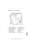 3
3 -
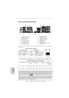 4
4 -
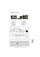 5
5 -
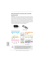 6
6 -
 7
7 -
8
-
9
-
10
-
11
-
12
-
13
-
14
-
15
-
16
-
17
-
18
-
19
-
20
-
21
-
22
-
23
-
24
-
25
-
26
-
27
-
28
-
29
-
30
-
31
-
32
-
33
-
34
-
35
-
36
-
37
-
38
-
39
-
40
-
41
-
42
-
43
-
44
-
45
-
46
-
47
-
48
-
49
-
50
-
51
-
52
-
53
-
54
-
55
-
56
-
57
-
58
-
59
-
60
-
61
-
62
-
63
-
64
-
65
-
66
-
67
-
68
-
69
-
70
-
71
-
72
-
73
-
74
-
75
-
76
-
77
-
78
-
79
-
80
-
81
-
82
-
83
-
84
-
85
-
86
-
87
-
88
-
89
-
90
-
91
-
92
-
93
-
94
-
95
-
96
-
97
-
98
-
99
-
100
-
101
-
102
-
103
-
104
-
105
-
106
-
107
-
108
-
109
-
110
-
111
-
112
-
113
-
114
-
115
-
116
-
117
-
118
-
119
-
120
-
121
-
122
-
123
-
124
-
125
-
126
-
127
-
128
-
129
-
130
-
131
-
132
-
133
-
134
-
135
-
136
-
137
-
138
-
139
-
140
-
141
-
142
-
143
-
144
-
145
-
146
-
147
-
148
-
149
-
150
-
151
-
152
-
153
-
154
-
155
-
156
-
157
-
158
-
159
-
160
-
161
-
162
-
163
-
164
-
165
-
166
-
167
-
168
-
169
-
170
-
171
-
172
-
173
-
174
-
175
-
176
-
177
-
178
-
179
-
180
-
181
-
182
-
183
-
184
-
185
-
186
-
187
-
188
-
189
-
190
-
191
-
192
-
193
-
194
-
195
-
196
-
197
-
198
-
199
-
200
-
201
-
202
-
203
-
204
-
205
-
206
-
207
-
208
-
209
-
210
-
211
-
212
-
213
-
214
-
215
-
216
-
217
-
218
-
219
-
220
-
221
-
222
-
223
-
224
-
225
-
226
-
227
-
228
-
229
-
230
-
231
-
232
-
233
-
234
-
235
-
236
-
237
-
238
-
239
-
240
-
241
-
242
-
243
 |
 |

1
ASRock
H67M-ITX/HT / H67M-ITX
Motherboard
English
Copyright Notice:
No part of this installation guide may be reproduced, transcribed, transmitted, or trans-
lated in any language, in any form or by any means, except duplication of documentation
by the purchaser for backup purpose, without written consent of ASRock Inc.
Products and corporate names appearing in this guide may or may not be registered
trademarks or copyrights of their respective companies, and are used only for identi
fi
ca-
tion or explanation and to the owners’ bene
fi
t, without intent to infringe.
Disclaimer:
Speci
fi
cations and information contained in this guide are furnished for informational use
only and subject to change without notice, and should not be constructed as a commit-
ment by ASRock. ASRock assumes no responsibility for any errors or omissions that may
appear in this guide.
With respect to the contents of this guide, ASRock does not provide warranty of any kind,
either expressed or implied, including but not limited to the implied warranties or condi-
tions of merchantability or
fi
tness for a particular purpose. In no event shall ASRock, its
directors, of
fi
cers, employees, or agents be liable for any indirect, special, incidental, or
consequential damages (including damages for loss of pro
fi
ts, loss of business, loss of
data, interruption of business and the like), even if ASRock has been advised of the pos-
sibility of such damages arising from any defect or error in the guide or product.
This device complies with Part 15 of the FCC Rules. Operation is subject to the following
two conditions:
(1) this device may not cause harmful interference, and
(2) this device must accept any interference received, including interference that
may cause undesired operation.
CALIFORNIA, USA ONLY
The Lithium battery adopted on this motherboard contains Perchlorate, a toxic substance
controlled in Perchlorate Best Management Practices (BMP) regulations passed by the
California Legislature. When you discard the Lithium battery in California, USA, please
follow the related regulations in advance.
“Perchlorate Material-special handling may apply, see
www.dtsc.ca.gov/hazardouswaste/perchlorate”
ASRock Website: http://www.asrock.com
Published January 2011
Copyright
©
2011 ASRock INC. All rights reserved.