ASRock H81M-VG4 User Manual
ASRock H81M-VG4 Manual
 |
View all ASRock H81M-VG4 manuals
Add to My Manuals
Save this manual to your list of manuals |
ASRock H81M-VG4 manual content summary:
- ASRock H81M-VG4 | User Manual - Page 1
User Manual - ASRock H81M-VG4 | User Manual - Page 2
change without notice, and should not be constructed as a commitment by ASRock. ASRock assumes no responsibility for any errors or omissions that may appear in CALIFORNIA, USA ONLY The Lithium battery adopted on this motherboard contains Perchlorate, a toxic substance controlled in Perchlorate Best - ASRock H81M-VG4 | User Manual - Page 3
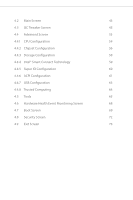
Features 6 1.4 Motherboard Layout 9 1.5 I/O Panel 13 Chapter 2 Installation 16 2.1 Installing the CPU 17 2.2 Installing the CPU Fan and Drivers 30 3.2 A-Tuning 31 3.3 Intel® Smart Connect Technology 34 3.4 Start8 38 Chapter 4 UEFI SETUP UTILITY 41 4.1 Introduction 41 4.1.1 UEFI - ASRock H81M-VG4 | User Manual - Page 4
4.2 Main Screen 43 4.3 OC Tweaker Screen 45 4.4 Advanced Screen 53 4.4.1 CPU Configuration 54 4.4.2 Chipset Configuration 56 4.4.3 Storage Configuration 58 4.4.4 Intel® Smart Connect Technology 59 4.4.5 Super IO Configuration 60 4.4.6 ACPI Configuration 61 4.4.7 USB Configuration - ASRock H81M-VG4 | User Manual - Page 5
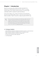
VGA cards and CPU support list on ASRock's website as well. ASRock website http://www.asrock.com. 1.1 Package Contents • ASRock H81M-HG4/H81M-DG4/H81M-VG4 Motherboard (Micro ATX Form Factor) • ASRock H81M-HG4/H81M-DG4/H81M-VG4 Quick Installation Guide • ASRock H81M-HG4/H81M-DG4/H81M-VG4 Support CD - ASRock H81M-VG4 | User Manual - Page 6
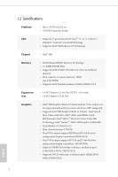
Platform CPU • Micro ATX Form Factor • All Solid Capacitor design • Supports 4th generation Intel® CoreTM i7 / i5 / i3 / Xeon® / Pentium® / Celeron® in LGA1150 Package • Supports Intel® Turbo Boost 2.0 Technology Chipset • Intel® H81 Memory • Dual Channel DDR3 Memory Technology • 2 x DDR3 DIMM - ASRock H81M-VG4 | User Manual - Page 7
HDMI Port (H81M-HG4) • Supports Full HD 1080p Blu-ray (BD) playback with DVI-D and Ports (H81M-DG4) Audio • 5.1 CH HD Audio (Realtek ALC662 Audio Codec) LAN • PCIE x1 Gigabit LAN 10/100/1000 Mb/s • Realtek RTL8111G • Supports Wake-On-LAN • Supports LAN Cable Detection • Supports Energy Efficient - ASRock H81M-VG4 | User Manual - Page 8
Support 4 USB 2.0 ports) BIOS Feature • 32Mb AMI UEFI Legal BIOS with Multilingual GUI support • ACPI 1.1 Compliance Wake Up Events • SMBIOS 2.3.1 Support • CPU, DRAM, PCH 1.05V, PCH 1.5V Voltage Multi-adjust- ment Support CD • Drivers +5V, +3.3V, CPU Vcore OS • Microsoft® Windows® 8.1 32-bit / - ASRock H81M-VG4 | User Manual - Page 9
for possible damage caused by overclocking. Due to limitation, the actual memory size may be less than 4GB for the reservation for system usage under Windows® 32-bit operating systems. Windows® 64-bit operating systems do not have such limitations. You can use ASRock XFast RAM to utilize the memory - ASRock H81M-VG4 | User Manual - Page 10
improved utilities, including XFast RAM, Dehumidifier, Good Night LED, FAN-Tastic Tuning, OC Tweaker and a whole lot more. ASRock Instant Flash ASRock Instant Flash is a BIOS flash utility embedded in Flash ROM. This convenient BIOS update tool allows you to update the system BIOS in a few clicks - ASRock H81M-VG4 | User Manual - Page 11
S4/S5 state. ASRock Easy Driver Installer For users that don't have an optical disk drive to install the drivers from our support CD, Easy Driver Installer is a handy tool in the UEFI that installs the LAN driver to your system via an USB storage device, then downloads and installs the other - ASRock H81M-VG4 | User Manual - Page 12
completely change your user experience and behavior. ASRock Restart to UEFI Windows® 8 brings the ultimate boot up experience. The lightning boot up speed makes it hard to access the UEFI setup. ASRock Restart to UEFI allows users to enter the UEFI automatically when turning on the PC. By enabling - ASRock H81M-VG4 | User Manual - Page 13
Keyboard /Mouse 1.4 Motherboard Layout H81M-HG4: X Fast LAN H81M-HG4/H81M-DG4/H81M-VG4 1 2 3 ATX12V1 PWR_FAN1 X Fast RAM DDR3_A1 (64 bit, H81M-HG4 X Fast USB 8 USB 3.0 PCIE1 9 Audio CODEC Super I/O RoHS CHA_FAN1 Intel H81 HD_AUDIO1 CI1 1 IR1 1 1 COM1 1 PCIE2 LPT1 32Mb BIOS - ASRock H81M-VG4 | User Manual - Page 14
RJ-45 1 B: USB3 SATA_3 SATA_2 6 CMOS Battery SATA_1 SATA_0 7 H81M-DG4 X Fast USB 8 USB 3.0 PCIE1 9 Audio CODEC Super I/O RoHS CHA_FAN1 Intel H81 HD_AUDIO1 CI1 1 IR1 1 1 COM1 1 PCIE2 LPT1 32Mb BIOS 1 SPEAKER1 1 USB4_5 1 USB6_7 1 1 TPMS1 PLED PWRBTN 1 HDLED RESET PANEL1 - ASRock H81M-VG4 | User Manual - Page 15
USB0 B: USB1 PS2 Keyboard /Mouse H81M-VG4: X Fast LAN H81M-HG4/H81M-DG4/H81M-VG4 1 2 3 ATX12V1 PWR_FAN1 X Fast RAM DDR3_A1 (64 bit, 240-pin H81M-VG4 X Fast USB 8 USB 3.0 PCIE1 9 Audio CODEC Super I/O RoHS CHA_FAN1 Intel H81 HD_AUDIO1 CI1 1 IR1 1 1 COM1 1 PCIE2 LPT1 32Mb BIOS - ASRock H81M-VG4 | User Manual - Page 16
Power Connector (ATX12V1) 2 Power Fan Connector (PWR_FAN1) 3 2 x 240-pin DDR3 DIMM Slots (DDR3_A1, DDR3_B1) 4 ATX Power Connector (ATXPWR1) 5 SATA2 Connector (SATA_3) 6 SATA2 Connector (SATA_2) 7 Header (CI1) 20 Front Panel Audio Header (HD_AUDIO1) 21 CPU Fan Connector (CPU_FAN1) 12 English - ASRock H81M-VG4 | User Manual - Page 17
1.5 I/O Panel H81M-HG4: 1 H81M-HG4/H81M-DG4/H81M-VG4 3 2 4 10 No. Description 1 USB 2.0 Ports (USB01) 2 LAN RJ-45 Port* 3 Line In (Light Blue) 4 Front Speaker (Lime) 5 Microphone (Pink) 9 8 7 6 5 No. Description 6 USB 2.0 Ports (USB23) 7 USB 3.0 Ports (USB3_01) 8 HDMI Port 9 D-Sub Port 10 - ASRock H81M-VG4 | User Manual - Page 18
H81M-DG4: 1 3 2 4 10 9 No. Description 1 USB 2.0 Ports (USB01) 2 LAN RJ-45 Port* 3 Line In (Light Blue) 4 Front Speaker (Lime) 5 Microphone (Pink) 8 7 6 5 No. Description 6 USB 2.0 Ports (USB23) 7 USB 3.0 Ports (USB3_01) 8 D-Sub Port 9 DVI-D Port 10 - ASRock H81M-VG4 | User Manual - Page 19
H81M-VG4: 1 H81M-HG4/H81M-DG4/H81M-VG4 3 2 4 9 No. Description 1 USB 2.0 Ports (USB01) 2 LAN RJ-45 Port* 3 Line In (Light Blue) 4 Front Speaker (Lime) 5 Microphone (Pink) 8 7 6 5 No. Description 6 USB 2.0 Ports (USB23) 7 USB 3.0 Ports (USB3_01) 8 D-Sub Port 9 PS/2 Mouse/Keyboard - ASRock H81M-VG4 | User Manual - Page 20
2 Installation This is a Micro ATX form factor motherboard. Before you install the motherboard, study the configuration of your chassis to ensure that the motherboard fits into it. Pre-installation Precautions Take note of the following precautions before you install motherboard components or change - ASRock H81M-VG4 | User Manual - Page 21
H81M-HG4/H81M-DG4/H81M-VG4 2.1 Installing the CPU 1. Before you insert the 1150-Pin CPU into the socket, please check if the PnP cap is on the socket, if the CPU surface is unclean, or if there are any bent pins in the socket. Do not force to insert the CPU into the socket if above situation is - ASRock H81M-VG4 | User Manual - Page 22
4 5 18 3 English - ASRock H81M-VG4 | User Manual - Page 23
H81M-HG4/H81M-DG4/H81M-VG4 Please save and replace the cover if the processor is removed. The cover must be placed if you wish to return the motherboard for after service. 19 English - ASRock H81M-VG4 | User Manual - Page 24
2.2 Installing the CPU Fan and Heatsink 1 2 CPU_FAN English 20 - ASRock H81M-VG4 | User Manual - Page 25
H81M-HG4/H81M-DG4/H81M-VG4 2.3 Installing Memory Modules (DIMM) This motherboard provides two 240-pin DDR3 (Double Data Rate 3) DIMM slots, and supports Dual Channel Memory Technology. 1. For dual channel configuration, you always need to install identical (the same brand, speed, size and chip-type) - ASRock H81M-VG4 | User Manual - Page 26
1 2 3 22 English - ASRock H81M-VG4 | User Manual - Page 27
H81M-HG4/H81M-DG4/H81M-VG4 2.4 Expansion Slots (PCI Express Slots) There are 2 PCI Express slots on the motherboard. Before installing an expansion card, please make sure that the power supply is switched off or the power cord is unplugged. Please read the documentation of the expansion card and - ASRock H81M-VG4 | User Manual - Page 28
short pin2 and pin3 on CLRCMOS1 for 5 seconds. However, please do not clear the CMOS right after you update the BIOS. If you need to clear the CMOS when you just finish updating the BIOS, you must boot up the system first, and then shut it down before you do the clear-CMOS action - ASRock H81M-VG4 | User Manual - Page 29
H81M-HG4/H81M-DG4/H81M-VG4 2.6 Onboard Headers and Connectors Onboard headers and connectors are NOT jumpers. Do NOT place jumper caps over these headers and connectors. Placing jumper caps over the headers and connectors will cause permanent damage to the motherboard. System Panel Header (9-pin - ASRock H81M-VG4 | User Manual - Page 30
) USB_PWR P-7 P+7 GND DUMMY 1 GND P+6 P-6 USB_PWR Besides four USB 2.0 ports on the I/O panel, there are two headers on this motherboard. Each USB 2.0 header can support two ports. Front Panel Audio Header (9-pin HD_AUDIO1) (see p.9, 10, 11, No. 20) GND PRESENCE# MIC_RET OUT_RET 1 OUT2_L J_SENSE - ASRock H81M-VG4 | User Manual - Page 31
H81M-HG4/H81M-DG4/H81M-VG4 1. High Definition Audio supports Jack Sensing, but the panel wire on the chassis must support HDA to function correctly. Please follow the instructions in our manual and chassis manual to install your system. 2. If you use an AC'97 audio panel, please install it to the - ASRock H81M-VG4 | User Manual - Page 32
No. 1) This motherboard provides an 4-pin ATX 12V power connector. Infrared Module Header (5-pin IR1) (see p.9, 10, 11, No. 18) Serial Port Header (9-pin COM1) (see p.9, 10, 11, No. 17) IRTX +5VSB DUMMY 1 GND IRRX RRXD1 DDTR#1 DDSR#1 CCTS#1 1 RRI#1 RRTS#1 GND TTXD1 DDCD#1 This header supports an - ASRock H81M-VG4 | User Manual - Page 33
H81M-HG4/H81M-DG4/H81M-VG4 Print Port Header (25-pin LPT1) (see p.9, 10, 11, No. 16) AFD# ERROR# PINIT# SLIN# GND 1 SPD7 SPD6 ACK# SPD5 BUSY SPD4 PE SPD3 SLCT - ASRock H81M-VG4 | User Manual - Page 34
required drivers. Therefore, the drivers you install can work properly. Utilities Menu The Utilities Menu shows the application software that the motherboard supports. Click on a specific item then follow the installation wizard to install it. To improve Windows 7 compatibility, please download and - ASRock H81M-VG4 | User Manual - Page 35
H81M-HG4/H81M-DG4/H81M-VG4 3.2 A-Tuning A-Tuning is ASRock's multi purpose software suite with a new interface, more new features and improved utilities, including XFast RAM, Dehumidifier, Good Night LED, FAN-Tastic Tuning, OC Tweaker and a whole lot more. 3.2.1 Installing A-Tuning When you install - ASRock H81M-VG4 | User Manual - Page 36
then assign which files should be stored in the RAM drive. Good Night LED Switch off the Power/HDD/LAN LEDs when the system is on, and automatically next speed level when the assigned temperature is met. Dehumidifier Prevent motherboard damages due to dampness. Enable this function and configure the - ASRock H81M-VG4 | User Manual - Page 37
OC Tweaker Configurations for overclocking the system. H81M-HG4/H81M-DG4/H81M-VG4 System Info View information about the system. Tech Service Contact Tech Service. 33 English - ASRock H81M-VG4 | User Manual - Page 38
Intel® Smart Connect Technology is a feature that periodically wakes your computer from Windows® sleep state to refresh email or social networking applications. It saves your waiting time and keeps the content always up-to-date. 3.3.1 System Requirements • Confirm whether your motherboard supports - ASRock H81M-VG4 | User Manual - Page 39
H81M-VG4 3.3.2 Setup Guide Installing ASRock Smart Connect Utility Step 1 Install ASRock Smart Connect Utility, which is located in the folder at the following path of the Support CD: \ ASRock Utility > Smart Connect. Step 2 Once installed, run ASRock Smart Connect from your desktop or go to Windows - ASRock H81M-VG4 | User Manual - Page 40
Step 3 Click the Add button. Take Foxmail as an example, add Foxmail to the Application list. Step 4 Select Foxmail from the Application List, then click the arrow pointing right to add this application to the Smart Connect List. Step 5 Click Apply to enable Smart Connect. 36 English - ASRock H81M-VG4 | User Manual - Page 41
H81M-HG4/H81M-DG4/H81M-VG4 Step 6 Double-click the Intel® Smart Connect Technology Manager icon Windows system tray. in the Step 7 Drag the slider to configure how often the system will connect to the network to download updates. Shorter durations will provide more frequent updates, but may - ASRock H81M-VG4 | User Manual - Page 42
Installing Start8 Install Start8, which is located in the folder at the following path of the Support CD: \ ASRock Utility > Start8. 3.4.2 Configuring Start8 Style Select between the Windows 7 style and Windows 8 style Start Menu. Then select the theme of the Start Menu and customize the style of - ASRock H81M-VG4 | User Manual - Page 43
Configure H81M-HG4/H81M-DG4/H81M-VG4 Configure provides configuration options, including icon sizes, which shortcuts you want Start Menu to display, quick access to recently used apps, the functionality of the power button, and more. Control 39 English - ASRock H81M-VG4 | User Manual - Page 44
Control lets you configure what a click on the start button or a press on the Windows key does. Desktop Desktop allows you to disable the hot corners when you are working on the desktop. It also lets you choose whether or - ASRock H81M-VG4 | User Manual - Page 45
H81M-HG4/H81M-DG4/H81M-VG4 Chapter 4 UEFI SETUP UTILITY 4.1 Introduction ASRock Interactive UEFI is a blend of system configuration tools, cool sound effects and stunning visuals. Not only will it make BIOS setup less difficult but also a lot more amusing. This section explains how to use the UEFI - ASRock H81M-VG4 | User Manual - Page 46
4.1.2 Navigation Keys Use < > key or < > key to choose among the selections on the menu bar, and use < > key or < > key to move the cursor up or down to select items, then press to get into the sub screen. You can also use the mouse to click your required item. Please check the following - ASRock H81M-VG4 | User Manual - Page 47
H81M-HG4/H81M-DG4/H81M-VG4 4.2 Main Screen When you enter the UEFI Setup Utility, the Main screen will appear and display the system overview. H81M-HG4 Active Page on Entry Select the default page when entering the UEFI setup utility. UEFI Guide UEFI Guide is a quick tutorial for ASRock's UEFI setup - ASRock H81M-VG4 | User Manual - Page 48
H81M-DG4 H81M-VG4 44 English - ASRock H81M-VG4 | User Manual - Page 49
should be done at your own risk and expense. Non-Z OC Non-Z OC allows users with a K-Series Haswell processor to overclock their non Z87 chipset motherboards. Load Optimized GPU OC Setting Please note that overclocking may cause damage to your CPU and motherboard. It should be done at your own risk - ASRock H81M-VG4 | User Manual - Page 50
mode allows you to keep the max CPU ratio as your setting without throttling. Please note that overclocking may cause damage to your CPU and motherboard. It should be done at your own risk and expense. Intel SpeedStep Technology Intel SpeedStep technology allows processors to switch between multiple - ASRock H81M-VG4 | User Manual - Page 51
H81M-HG4/H81M-DG4/H81M-VG4 Long Duration Maintained Configure the period of time until the CPU ratio is lowered when the Long Duration Power Limit is exceeded. Short Duration Power Limit Configure Package Power Limit 2 in watts. When the limit is exceeded, the CPU ratio will be lowered immediately. - ASRock H81M-VG4 | User Manual - Page 52
DRAM Configuration CAS# Latency (tCL) The time between sending a column address to the memory and the beginning of the data in response. RAS# to CAS# Delay (tRCD) The number of clock cycles required between the opening of a row of memory and accessing columns within it. Row Precharge Time (tRP) The - ASRock H81M-VG4 | User Manual - Page 53
H81M-HG4/H81M-DG4/H81M-VG4 Refresh Cycle Time (tRFC) The number of clocks from a window in which four activates are allowed the same rank. CAS Write Latency (tCWL) Configure CAS Write Latency. tREFI Configure refresh cycles at an average periodic interval. tCKE Configure the period of time the DDR3 - ASRock H81M-VG4 | User Manual - Page 54
tWRRDDR Configure between module write to read delay from different ranks. tWRRDDD Use this to change DRAM tRRSR Auto/Manual settings. The default is [Auto]. Configure between module write to read delay from different DIMMs. tWRWR Configure between module write to write delay. tWRWRDR Configure - ASRock H81M-VG4 | User Manual - Page 55
H81M-HG4/H81M-DG4/H81M-VG4 ODT WR (CHB) Configure the memory on die termination resistors' WR for channel B. ODT NOM (CHA) Use this to change ODT (CHA) Auto/Manual settings. The default is [Auto]. ODT NOM (CHB) Use this to change ODT (CHB) Auto/Manual boost or deduction. CPU Vcore Voltage Mode Auto - ASRock H81M-VG4 | User Manual - Page 56
the voltage for the System Agent. Setting the voltage higher may increase system stability when overclocking. CPU Analog IO Voltage Offset CPU I/O Analog Voltage. CPU Digital IO Voltage Offset CPU I/O Digital Voltage. CPU Integrated VR Faults Disable FIVR Faults to raise the threshold to trigger - ASRock H81M-VG4 | User Manual - Page 57
H81M-HG4/H81M-DG4/H81M-VG4 4.4 Advanced Screen In this section, you may set the configurations for the following items: CPU Configuration, Chipset Configuration, Storage Configuration, Intel® Smart Connect Technology, Super IO Configuration, ACPI Configuration, USB Configuration and Trusted - ASRock H81M-VG4 | User Manual - Page 58
sleep state for lower power consumption. CPU C6 State Support Enable C6 deep sleep state for lower power consumption. CPU C7 State Support Enable C7 deep sleep state for lower power consumption. Package C State Support Enable CPU, PCIe, Memory, Graphics C State Support for power saving. 54 English - ASRock H81M-VG4 | User Manual - Page 59
H81M-HG4/H81M-DG4/H81M-VG4 CPU Thermal Throttling Enable CPU internal thermal control mechanisms to keep the CPU from overheating. No-Execute Memory Protection Processors with No-Execution Memory Protection Technology may prevent certain classes of malicious buffer overflow attacks. Intel - ASRock H81M-VG4 | User Manual - Page 60
4.4.2 Chipset Configuration Primary Graphics Adapter Select a primary VGA. VT-d Intel® graphics processor when the system boots up. IGPU Multi-Monitor Select disable to disable the integrated graphics when an external graphics card is installed. Select enable to keep the integrated graphics - ASRock H81M-VG4 | User Manual - Page 61
H81M-HG4/H81M-DG4/H81M-VG4 Render Standby Power down the render unit when the GPU is idle for lower power consumption. Onboard HD Audio Enable/disable onboard HD audio. Set to Auto to enable onboard HD audio and automatically disable it when a sound card Night LED, the Power/LAN LEDs will be switched - ASRock H81M-VG4 | User Manual - Page 62
Link Power Management allows SATA devices to enter a low power state during periods of inactivity to save power. It is only supported by AHCI mode. Hard Disk S.M.A.R.T. S.M.A.R.T stands for Self-Monitoring, Analysis, and Reporting Technology. It is a monitoring system for computer hard disk - ASRock H81M-VG4 | User Manual - Page 63
H81M-HG4/H81M-DG4/H81M-VG4 4.4.4 Intel® Smart Connect Technology Intel® Smart Connect Technology Intel® Smart Connect Technology automatically updates your email and social networks, such as Twitter, Facebook, etc. while the computer is in sleep mode. 59 English - ASRock H81M-VG4 | User Manual - Page 64
4.4.5 Super IO Configuration Serial Port Enable or disable the Serial port. Serial Port Address Select the address of the Serial port. Infrared Port Enable or disable the Infrared port. Parallel Port Enable or disable the Parallel port. Change Settings Select the address of the Parallel port. Device - ASRock H81M-VG4 | User Manual - Page 65
H81M-HG4/H81M-DG4/H81M-VG4 Suspend to RAM It Enable the High Precision Event Timer for better performance and to pass WHQL tests. PS/2 Keyboard Power On Allow the system to be waked up by up by a PCIE device and enable wake on LAN. Ring-In Power On Allow the system to be waked up by onboard - ASRock H81M-VG4 | User Manual - Page 66
RTC Alarm Power On Allow the system to be waked up by the real time clock alarm. Set it to By OS to let it be handled by your operating system. USB Keyboard/Remote Power On Allow the system to be waked up by an USB keyboard or remote controller. USB Mouse Power On Allow the system to be waked up by - ASRock H81M-VG4 | User Manual - Page 67
4.4.7 USB Configuration H81M-HG4/H81M-DG4/H81M-VG4 USB Controller Enable or disable all the USB 2.0 ports. Intel USB 3.0 Mode Enable or disable all the USB 3.0 ports. It is recommended to select [Smart Auto]. Legacy USB Support Enable or disable Legacy OS Support for USB 2.0 devices. If you - ASRock H81M-VG4 | User Manual - Page 68
4.4.8 Trusted Computing Security Device Support Enable to activate Trusted Platform Module (TPM) security for your hard disk drives. 64 English - ASRock H81M-VG4 | User Manual - Page 69
Tools H81M-HG4/H81M-DG4/H81M-VG4 UEFI Tech Service Contact ASRock Tech Service if you are having trouble with your PC. Please setup network configuration before using UEFI Tech Service. Easy Driver Installer For users that don't have an optical disk drive to install the drivers from our support CD - ASRock H81M-VG4 | User Manual - Page 70
effects in the setup utility. UEFI Download Server Select a server to download the UEFI firmware. Dehumidifier Function If Dehumidifier process before it returns to S4/S5 state. Dehumidifier CPU Fan Setting Configure the speed of the CPU fan while Dehumidifier is enabled. The higher the value, - ASRock H81M-VG4 | User Manual - Page 71
H81M-HG4/H81M-DG4/H81M-VG4 Save User Default Type a profile name and press enter to save your settings as user default. Load User Default Load previously saved user defaults. 67 English - ASRock H81M-VG4 | User Manual - Page 72
of the hardware on your system, including the parameters of the CPU temperature, motherboard temperature, fan speed and voltage. CPU Fan 1 Setting Select a fan mode for CPU Fans 1, or choose Customize to set 5 CPU temperatures and assign a respective fan speed for each temperature. Chassis Fan - ASRock H81M-VG4 | User Manual - Page 73
H81M-HG4/H81M-DG4/H81M-VG4 4.7 Boot Screen This support UEFI GOP if you are using an external graphics card. Please notice that Ultra Fast mode will boot so fast that the only way to enter this UEFI Setup Utility is to Clear CMOS or run the Restart to UEFI utility in Windows. Boot From Onboard LAN - ASRock H81M-VG4 | User Manual - Page 74
automatically restores the default settings. CSM (Compatibility Support Module) CSM Enable to launch the Compatibility Support Module. Please do not disable unless you're running a WHCK test. If you are using Windows 8 64-bit and all of your devices support UEFI, you may also disable CSM for faster - ASRock H81M-VG4 | User Manual - Page 75
H81M-HG4/H81M-DG4/H81M-VG4 Launch PXE OpROM Policy Select UEFI only to run those that support UEFI option ROM only. Select Legacy only to run those that support legacy option ROM only. Launch Storage OpROM Policy Select UEFI only to run those that support UEFI option ROM only. Select Legacy only to - ASRock H81M-VG4 | User Manual - Page 76
account. Only the administrator has authority to change the settings in the UEFI Setup Utility. Leave it blank and press enter to remove the password. in the UEFI Setup Utility. Leave it blank and press enter to remove the password. Secure Boot Enable to support Windows 8 Secure Boot. 72 English - ASRock H81M-VG4 | User Manual - Page 77
4.9 Exit Screen H81M-HG4/H81M-DG4/H81M-VG4 Save Changes and Exit When you select this option the following message, "Save configuration changes and exit setup?" will pop out. Select [OK] to save changes and exit the UEFI SETUP Utility. Discard Changes and Exit When you select this option the - ASRock H81M-VG4 | User Manual - Page 78
or want to know more about ASRock, you're welcome to visit ASRock's website at http://www.asrock.com; or you may contact your dealer for further information. For technical questions, please submit a support request form at http://www.asrock.com/support/tsd.asp ASRock Incorporation 2F., No.37, Sec
-
 1
1 -
 2
2 -
 3
3 -
 4
4 -
 5
5 -
 6
6 -
 7
7 -
8
-
9
-
10
-
11
-
12
-
13
-
14
-
15
-
16
-
17
-
18
-
19
-
20
-
21
-
22
-
23
-
24
-
25
-
26
-
27
-
28
-
29
-
30
-
31
-
32
-
33
-
34
-
35
-
36
-
37
-
38
-
39
-
40
-
41
-
42
-
43
-
44
-
45
-
46
-
47
-
48
-
49
-
50
-
51
-
52
-
53
-
54
-
55
-
56
-
57
-
58
-
59
-
60
-
61
-
62
-
63
-
64
-
65
-
66
-
67
-
68
-
69
-
70
-
71
-
72
-
73
-
74
-
75
-
76
-
77
-
78
 |
 |

User Manual