ASRock J4105M Quick Installation Guide
ASRock J4105M Manual
 |
View all ASRock J4105M manuals
Add to My Manuals
Save this manual to your list of manuals |
ASRock J4105M manual content summary:
- ASRock J4105M | Quick Installation Guide - Page 1
change without notice, and should not be constructed as a commitment by ASRock. ASRock assumes no responsibility for any errors or omissions that may appear in CALIFORNIA, USA ONLY The Lithium battery adopted on this motherboard contains Perchlorate, a toxic substance controlled in Perchlorate Best - ASRock J4105M | Quick Installation Guide - Page 2
if the goods fail to be of acceptable quality and the failure does not amount to a major failure. If you require assistance please call ASRock Tel : +886-2-28965588 ext.123 (Standard International call charges apply) The terms HDMI™ and HDMI High-Definition Multimedia Interface, and the HDMI logo - ASRock J4105M | Quick Installation Guide - Page 3
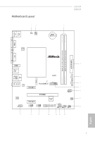
Motherboard Layout 12 1 CLRMOS1 CPU_FAN1 PS2 Mouse PS2 Keyboard VGA1 BIOS ROM J4105M J4005M 3 CMOS Battery AT X P W R 1 DDR4_A1 (64 bit, 288-pin module) DDR4_A2 (64 bit, 288-pin module) DVI1 4 HDMI1 USB 3.1 Gen1 T: USB0 B: USB1 Top: LINE IN - ASRock J4105M | Quick Installation Guide - Page 4
No. Description 1 Clear CMOS Jumper (CLRMOS1) 2 CPU Fan Connector (CPU_FAN1) 3 2 x 288-pin DDR4 DIMM Slots (DDR4_A1, DDR4_A2) 4 ATX Power Connector (ATXPWR1) 5 SATA3 Connector (SATA3_1) 6 SATA3 Connector (SATA3_2) 7 USB 3.1 Gen1 Header (USB3_1_2) 8 System Panel Header (PANEL1) 9 Chassis Fan - ASRock J4105M | Quick Installation Guide - Page 5
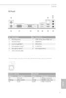
I/O Panel 1 J4105M J4005M 3 2 4 11 10 No. Description 1 PS/2 Mouse Port 2 LAN RJ-45 Port* 3 Line In (Light Blue)** 4 Front Speaker (Lime)** 5 Microphone (Pink)** 6 USB 2.0 Ports (USB01) 9 8 7 6 5 No. - ASRock J4105M | Quick Installation Guide - Page 6
7.1 CH HD Audio, it is required to use an HD front panel audio module and enable the multichannel audio feature through the audio driver. Please set Speaker Configuration to "7.1 Speaker"in the Realtek HD Audio Manager. Function of the Audio Ports in 7.1-channel Configuration: Port Light Blue - ASRock J4105M | Quick Installation Guide - Page 7
the latest VGA cards and CPU support list on ASRock's website as well. ASRock website http://www.asrock.com. 1.1 Package Contents • ASRock J4105M / J4005M Motherboard (Micro ATX Form Factor) • ASRock J4105M / J4005M Quick Installation Guide • ASRock J4105M / J4005M Support CD • 2 x Serial ATA (SATA - ASRock J4105M | Quick Installation Guide - Page 8
design CPU • Intel® Quad-Core Processor J4105 (up to 2.5 GHz) (for J4105M) • Intel® Dual-Core Processor J4005 (up to 2.7 GHz) (for J4005M) Memory • Dual Channel DDR4 Memory Technology • 2 x DDR4 DIMM Slots * 2GB DRAM per module is not supported. • Supports DDR4 2400/2133 non-ECC, un-buffered - ASRock J4105M | Quick Installation Guide - Page 9
J4105M J4005M • Supports D-Sub with max. resolution up to 2048x1536 @ 60Hz • Supports Auto Lip Sync, xvYCC and HBR (High Bit Rate Audio) with HDMI Port (Compliant HDMI monitor is required) • Supports HDCP with DVI-D and HDMI Ports • Supports driver. • Supports Surge Protection • ELNA Audio Caps LAN • - ASRock J4105M | Quick Installation Guide - Page 10
pin) • 1 x 24 pin ATX Power Connector • 1 x Front Panel Audio Connector • 3 x USB 2.0 Headers (Support 5 USB 2.0 ports) (Supports ESD Protection) • 1 x USB 3.1 Gen1 Header (Supports 2 USB 3.1 Gen1 ports) (Supports ESD Protection) • AMI UEFI Legal BIOS with GUI support • Supports Plug and Play • ACPI - ASRock J4105M | Quick Installation Guide - Page 11
it. Pre-installation Precautions Take note of the following precautions before you install motherboard components or change any motherboard settings. • Make sure to unplug the power cord before installing or removing the motherboard. Failure to do so may cause physical injuries to you and damages to - ASRock J4105M | Quick Installation Guide - Page 12
provides two 288-pin DDR4 (Double Data Rate 4) DIMM slots, and supports Dual Channel Memory Technology. 1. It is not allowed to install a DDR, DDR2 or DDR3 memory module into a DDR4 slot; otherwise, this motherboard and DIMM may be damaged. 2. The DIMM only fits in one correct orientation - ASRock J4105M | Quick Installation Guide - Page 13
J4105M J4005M 1 2 3 11 English - ASRock J4105M | Quick Installation Guide - Page 14
slots on the motherboard. Before installing an expansion card, please make sure that the power supply is switched off or the power cord is unplugged. lane width cards. Warning: To ensure better graphics compability, the BIOS is set to "boot from Onboard VGA" as default even the user install a VGA - ASRock J4105M | Quick Installation Guide - Page 15
J4105M J4005M 2.3 Jumpers Setup The illustration power supply. After waiting for 15 seconds, use a jumper cap to short pin2 and pin3 on CLRMOS1 for 5 seconds. However, please do not clear the CMOS right after you update the BIOS. If you need to clear the CMOS when you just finish updating the BIOS - ASRock J4105M | Quick Installation Guide - Page 16
jumper caps over the headers and connectors will cause permanent damage to the motherboard. System Panel Header (9-pin PANEL1) (see p.1, No. 8) PLED+ PLEDPWRBTN# GND 1 GND RESET# GND HDLEDHDLED+ Connect the power switch, reset switch and system status indicator on the chassis to this header - ASRock J4105M | Quick Installation Guide - Page 17
J4105M J4005M Serial ATA3 Connectors (SATA3_1: see p.1, No. 5) (SATA3_2: see p.1, No. 6) SATA3_1 SATA3_2 These two SATA3 connectors support SATA data cables for internal storage devices is one header on this motherboard. This USB 3.1 Gen1 header can support two ports. 1 Vbus - ASRock J4105M | Quick Installation Guide - Page 18
wire on the chassis must support HDA to function correctly. Please follow the instructions in our manual and chassis manual to install your system. 2. This motherboard provides a 24-pin ATX power connector. To use a 20-pin ATX power supply, please plug it along Pin 1 and Pin 13. This header supports - ASRock J4105M | Quick Installation Guide - Page 19
J4105M J4005M Print Port Header (25-pin LPT1) (see p.1, No. 14) STB# SPD0 SPD1 SPD2 SLCT SPD3 PE SPD4 BUSY SPD5 ACK# SPD6 SPD7 1 GND SLIN# PINIT# ERROR# AFD# This is an interface for print port cable that allows convenient connection of printer devices. English 17 - ASRock J4105M | Quick Installation Guide - Page 20
2.5 Intel® CNVi (Integrated WiFi/BT) Installation Guide The M.2, also known as the Next Generation Form Factor (NGFF), is a small size and versatile card edge connector that aims to replace mPCIe and mSATA. The M.2 Socket (Key E) supports type 2230 Intel® CNVi (Integrated WiFi/BT). Installing Intel® - ASRock J4105M | Quick Installation Guide - Page 21
J4105M J4005M Step 4 Tighten the screw with a screwdriver to secure the module into place. Please do not overtighten the screw as this might damage the module. A 19 English - ASRock J4105M | Quick Installation Guide - Page 22
tzter VGA-Karten und Prozessoren auf der ASRock-Webseite: ASRock-Webseite http://www.asrock.com. 1.1 Lieferumfang • ASRock J4105M / J4005M-Motherboard (Micro-ATX-Formfaktor) • ASRock J4105M / J4005M-Schnellinstallationsanleitung • ASRock J4105M / J4005M-Support-CD • 2 x Serial-ATA- (SATA) Datenkabel - ASRock J4105M | Quick Installation Guide - Page 23
ECC- Speicher • Systemspeicher, max. Kapazität: 8GB * Intel® Extreme Memory Profile (XMP) wird nicht unterstützt Erweiterungssteckplatz • 1 x PCI- Integrierte Intel® UHD Graphics 600: 12 EUs im Inneren (bis 750MHz) (bei J4105M) • Integrierte Intel® UHD Graphics 600: 12 EUs im Inneren (bis 700MHz) - ASRock J4105M | Quick Installation Guide - Page 24
Audio • Unterstützt D-Sub mit maximaler Auflösung von 2048 × 1536 bei 60 Hz • Unterstützt Auto-Lippensynchronizität, xvYCC und HBR (Audio mit hoher Bitrate) mit HDMI-Port (konformer HDMIMonitor erforderlich) • Unterstützt HDCP mit DVI-D- und HDMI-Ports • Unterstützt Blu-ray- (BD) Wiedergabe (Full - ASRock J4105M | Quick Installation Guide - Page 25
J4105M J4005M Anschluss • 1 x Druckerport-Anschlussleiste • 2 x COM-Anschluss-Stiftleiste • 1 x Gehäuseeingriff- und gegen elektrostatische Entladung) BIOSFunktion • AMI-UEFI-Legal-BIOS mit Unterstützung grafischer Benutzerschnittstellen • Unterstützt Webseite: http://www.asrock.com Deutsch 23 - ASRock J4105M | Quick Installation Guide - Page 26
3 an CLRMOS1 5 Sekunden lang mit einer Jumper-Kappe kurz. Löschen Sie den CMOS jedoch nicht direkt nach der BIOS-Aktualisierung. Falls Sie den CMOS direkt nach Abschluss der BIOS-Aktualisierung löschen müssen, starten Sie das System zunächst; fahren Sie es dann vor der CMOS-Löschung herunter. Bitte - ASRock J4105M | Quick Installation Guide - Page 27
Stiftleisten und Anschlüsse J4105M J4005M Integrierte Stiftleisten und Anschlüsse sind KEINE Jumper. Bringen Sie KEINE JumperKappen an diesen Stiftleisten und Anschlüssen an. Durch Anbringen von Jumper-Kappen an diesen Stiftleisten und Anschlüssen können Sie das Motherboard dauerhaft beschädigen - ASRock J4105M | Quick Installation Guide - Page 28
USB_6) (siehe S. 1, Nr. 13) USB_PWR PP+ GND DUMMY 1 GND P+ PUSB_PWR 1 GND P- P+ USB_PWR Es gibt drei Stiftleisten an diesem Motherboard. USB 3.1 Gen1-Stiftleiste (19-polig, USB3_1_2) (siehe S. 1, Nr. 7) IntA_P_D+ IntA_P_DGND IntA_P_SSTX+ IntA_P_SSTXGND IntA_P_SSRX+ IntA_P_SSRXVbus Es gibt eine - ASRock J4105M | Quick Installation Guide - Page 29
J4105M J4005M 1. High Definition Audio unterstützt Anschlusserkennung, der Draht am Gehä verbinden Sie das CPULüfterkabel mit dem Anschluss; der schwarze Draht gehört zum Erdungskontakt. Dieses Motherboard bietet einen 24-poligen ATX-Netzanschluss. Bitte schließen Sie es zur Nutzung eines 20-poligen - ASRock J4105M | Quick Installation Guide - Page 30
Druckanschluss-Stiftleiste STB# SPD0 Diese Schnittstelle ist für SPD1 (25-polig, LPT1) SLCT SPD2 SPD3 Druckerkabel vorgesehen PE SPD4 (siehe S. 1, Nr. 14) BUSY SPD5 ACK# SPD6 und ermöglicht bequemes SPD7 1 Anschließen von Druckern. GND SLIN# PINIT# ERROR# AFD# Deutsch 28 - ASRock J4105M | Quick Installation Guide - Page 31
disponible sur le site Internet de ASRock. Site Internet ASRock http://www.asrock.com. 1.1 Contenu de l'emballage • Carte mère ASRock J4105M / J4005M (facteur de forme Micro ATX) • Guide d'installation rapide ASRock J4105M / J4005M • CD d'assistance ASRock J4105M / J4005M • 2 x câbles de données - ASRock J4105M | Quick Installation Guide - Page 32
/2133 • Capacité max. de la mémoire système : 8Go * Intel® Extreme Memory Profile (XMP) n'est pas pris en charge Fente d'expansion Graphiques • 1 x Fente Intel® UHD 600 intégrés : 12 UE intégrées (Jusqu'à 750 MHz) (sur J4105M) • Graphiques Intel® UHD 600 intégrés : 12 UE intégrées (Jusqu'à 700MHz) - ASRock J4105M | Quick Installation Guide - Page 33
J4105M J4005M Audio Réseau Connectique du panneau arrière Stockage • Prend en charge le mode D-Sub avec une résolution maximale de 2048x1536 @ 60 Hz • Prend en - ASRock J4105M | Quick Installation Guide - Page 34
ports USB 3.1 Gen1 pris en charge) (Protection contre les décharges électrostatiques) Caractéristiques du BIOS • BIOS UEFI AMI avec prise en charge d'interface graphique • Prend en charge la fonction « Plug taillées de nos produits, veuillez visiter notre site : http://www.asrock.com Français 32 - ASRock J4105M | Quick Installation Guide - Page 35
J4105M J4005M 1.3 Configuration des cavaliers (jumpers) L'illustration ci-dessous vous n'effacez pas la CMOS immédiatement après avoir mis à jour le BIOS. Si vous avez besoin d'effacer les données CMOS après une mise à jour du BIOS, vous devez tout d'abord redémarrer le système, puis l'éteindre - ASRock J4105M | Quick Installation Guide - Page 36
1.4 Embases et connecteurs de la carte mère Les embases et connecteurs situés sur la carte NE SONT PAS des cavaliers. Ne placez JAMAIS de capuchons de cavaliers sur ces embases ou connecteurs. Placer un capuchon de cavalier sur ces embases ou connecteurs endommagera irrémédiablement votre carte mère - ASRock J4105M | Quick Installation Guide - Page 37
J4105M J4005M Connecteurs Serial ATA3 (SATA3_1: voir p.1, No. 5) (SATA3_2: voir p.1, No. 6) Embases USB 2.0 (USB_2_3 à 9 broches) (voir p.1, No. 12) (USB_4_5 à 9 broches) (voir p.1, No. 11) (USB_6 à 9 broches) (voir p.1, - ASRock J4105M | Quick Installation Guide - Page 38
Jack Sensing (détection de la fiche), mais le panneau grillagé du châssis doit être compatible avec la HDA pour fonctionner correctement. Veuillez suivre les instructions figurant dans notre manuel et dans le manuel du châssis pour installer votre système. 2. Si vous utilisez un panneau audio AC'97 - ASRock J4105M | Quick Installation Guide - Page 39
J4105M J4005M Embase de port d'impression (LPT1 à 25 broches) (voir p.1, No. 14) STB# SPD0 SPD1 SPD2 SLCT SPD3 PE SPD4 BUSY SPD5 ACK# SPD6 SPD7 1 Il s' - ASRock J4105M | Quick Installation Guide - Page 40
di CPU anche sul sito Web di ASRock. Sito Web di ASRock http://www.asrock. com. 1.1 Contenuto della confezione • Scheda madre J4105M / J4005M ASRock (fattore di forma Micro ATX) • Guida rapida di installazione ASRock J4105M / J4005M • CD di supporto ASRock J4105M / J4005M • 2 x cavi dati Serial ATA - ASRock J4105M | Quick Installation Guide - Page 41
un-buffered • Capacità max. della memoria di sistema: 8GB * Intel® Extreme Memory Profile (XMP) non è supportato Alloggio d'espansione • 1 x PCI Express 2.0 x16 ® UHD Graphics 600 integrata: 12 EU inside (fino a 750MHz) (per J4105M) • Intel® UHD Graphics 600 integrata: 12 EU inside (fino a 700MHz - ASRock J4105M | Quick Installation Guide - Page 42
configurare l'audio HD 7.1 canali, è necessario utilizzare un modulo pannello frontale audio HD ed attivare la funzione audio multicanale tramite il driver audio. • Supporta protezione da sovratensione • Cappucci audio ELNA LAN • 1 x PCIE LAN Gigabit 10/100/1000 Mb/s • Realtek RTL8111E • Supporto - ASRock J4105M | Quick Installation Guide - Page 43
J4105M J4005M Connettore • 1 x connettore porta stampa • 2 x collettore porta COM • 1 x collegamento altoparlante e ) (supporto protezione da scariche elettrostatiche) Funzionalità BIOS • AMI UEFI Legal BIOS con interfaccia di supporto • Supporta "Plug and : http://www.asrock.com Italiano 41 - ASRock J4105M | Quick Installation Guide - Page 44
pin 2 ed il pin 3 su CLRMOS1 per 5 secondi. Tuttavia, non azzerare la CMOS subito dopo aver aggiornato il BIOS. Se è necessario azzerare la CMOS dopo l'aggiornamento del BIOS, è necessario riavviare prima il sistema e in seguito spegnerlo prima di eseguire l'operazione di azzeramento della CMOS. La - ASRock J4105M | Quick Installation Guide - Page 45
1.4 Header e connettori su scheda J4105M J4005M Gli header e i connettori sulla scheda NON sono jumper. NON posizionare cappucci del jumper su questi header e connettori. Il posizionamento di cappucci del jumper su - ASRock J4105M | Quick Installation Guide - Page 46
Connettori Serial ATA3 (SATA3_1: vedere pag.1, n. 5) (SATA3_2: vedere pag.1, n. 6) SATA3_1 SATA3_2 Questi due connettori SATA3 supportano i cavi dati SATA per dispositivi di archiviazione interna, con una velocità di trasferimento dati fino a 6,0 Gb/s. Header USB 2.0 (USB_2_3 a 9 pin) (vedere pag - ASRock J4105M | Quick Installation Guide - Page 47
J4105M J4005M 1. L'audio ad alta definizione supporta le funzioni Jack sensing, ma il filo del pannello sullo chassis deve supportare HDA per funzionare correttamente. Seguire le istruzioni presenti nel nostro manuale e nel manuale dello chassis per installare il sistema. 2. Se si utilizza un - ASRock J4105M | Quick Installation Guide - Page 48
Header porta di stampa STB# SPD0 SPD1 (LPT1 a 25 pin) SLCT SPD2 SPD3 PE SPD4 (vedere pag. 1, n. 14) BUSY SPD5 ACK# SPD6 SPD7 1 GND SLIN# PINIT# ERROR# AFD# Si tratta di un'interfaccia per il cavo della porta di stampa che consente una comoda connessione ai dispositivi della stampante - ASRock J4105M | Quick Installation Guide - Page 49
J4105M / J4005M, una placa base fiable fabricada según el rigurosísimo control de calidad de ASRock. Ofrece un rendimiento excelente con un diseño resistente de acuerdo con el compromiso de calidad y resistencia de ASRock. Ya que las especificaciones de la placa base y el software de la BIOS podr - ASRock J4105M | Quick Installation Guide - Page 50
búfer • Capacidad máxima de memoria del sistema: 8GB * No se admite el Extreme Memory Profile (XMP) de Intel® Ranura de expansión • 1 x Ranura PCI Express 2.0 600 UHD Intel® integrados: 12 EUs interior (Hasta 750MHz) (para el J4105M) • Gráficos 600 UHD Intel® integrados: 12 EUs interior (Hasta - ASRock J4105M | Quick Installation Guide - Page 51
J4105M J4005M • Admite D-Sub con una resolución máxima de 2048x1536 @ 60 Hz • Admite sincronización automática entre audio y vídeo, xvYCC y HBR (audio de alta tasa de - ASRock J4105M | Quick Installation Guide - Page 52
(admite 2 puertos USB 3.1 Gen1). Admite protección contra descargas electrostáticas. Función de la BIOS • BIOS legal UEFI AMI compatible con interfaz gráfica de usuario • Compatible con "Plug and Play" información detallada del producto, visite nuestro sitio Web: http://www.asrock.com Español 50 - ASRock J4105M | Quick Installation Guide - Page 53
J4105M J4005M 1.3 Instalación de los puentes La instalación muestra cómo deben Sin embargo, no borre el CMOS justo después de que haya actualizado la BIOS. Si necesita borrar el CMOS cuando acabe de actualizar la BIOS, deberá arrancar el sistema primero y, a continuación, deberá apagarlo antes de - ASRock J4105M | Quick Installation Guide - Page 54
1.4 Conectores y cabezales incorporados Los cabezales y conectores incorporados NO son puentes. NO coloque tapas de puente sobre estos cabezales y conectores. Si coloca tapas de puente sobre los cabezales y conectores dañará de forma permanente la placa base. Cabezal del panel del sistema (PANEL1 - ASRock J4105M | Quick Installation Guide - Page 55
J4105M J4005M Conectores Serie ATA3 (SATA3_1: consulte la pág.1, N.º 5) (SATA3_2: consulte la pág.1, N.º 6) SATA3_1 SATA3_2 Estos dos conectores SATA3 admiten cables de datos SATA3 para dispositivos de almacenamiento - ASRock J4105M | Quick Installation Guide - Page 56
, el cable del panel del chasis deberá ser compatible con HDA para que pueda funcionar correctamente. Siga las instrucciones que se indican en nuestro manual y en el manual del chasis para instalar su sistema. 2. Si utiliza un panel de audio AC'97, colóquelo en el cabezal de audio del panel frontal - ASRock J4105M | Quick Installation Guide - Page 57
J4105M J4005M Cabezal de puerto de STB# SPD0 Ésta es una interfaz para el cable SPD1 impresión SLCT SPD2 SPD3 del puerto de impresión que PE - ASRock J4105M | Quick Installation Guide - Page 58
1 ASRock J4105M / J4005M ASRock ASRock BIOS ASRock ASRock VGA ASRock http://www.asrock.com. 1.1 ASRock J4105M / J4005M Micro ATX ASRock J4105M / J4005M ASRock J4105M / J4005M • 2 Serial ATA (SATA 1 M.2 1 56 - ASRock J4105M | Quick Installation Guide - Page 59
J4005M 1.2 Micro ATX ЦП Intel® J4105 (до 2,5 ГГц) (для J4105M) Intel® J4005 (до 2,7 J4005M) Память DDR4 • 2 x DDR4 DIMM DRAM 2 DDR4 2400/2133 без ECC 8 Intel® Extreme Memory Profile (XMP) не • 1 слот PCI Express 2.0 x16 (PCIE2 x1) • 2 слота PCI Express - ASRock J4105M | Quick Installation Guide - Page 60
Звук LAN D-Sub 2048x1536 60 Гц Auto Lip Sync, xvYCC и HBR (High Bit Rate Audio HDMI HDMI HDCP DVI-D и HDMI Full HD 1080p Blu-ray (BD DVI-D и HDMI • 7.1 Realtek ALC887) 7.1 HD Audio HD ELNA • PCIE x1 Gigabit LAN 10/100/1000 Realtek RTL8111E Energy Efficient Ethernet - ASRock J4105M | Quick Installation Guide - Page 61
USB 2.0 1 USB 3.1 Gen1 (2 порта USB 3.1 Gen1) (с BIOS • AMI UEFI Legal BIOS Plug and Play ACPI 5.0 JumperFree SMBIOS 3.0. 12 В, +5 В, +3,3 В, Vcore ЦП • Microsoft® Windows® 10 (64 • FCC, CE ErP/EuP ErP/EuP) http://www.asrock.com 59 - ASRock J4105M | Quick Installation Guide - Page 62
1.3 3 1 и 2 CMOS (CLRMOS1 1, № 1) CMOS CLRMOS1 CMOS 15 2 и 3 на CLRMOS1 на 5 CMOS BIOS CMOS BIOS CMOS CMOS. CMOS Clear Status BIOS. 60 - ASRock J4105M | Quick Installation Guide - Page 63
J4105M J4005M 1.4 9 PANEL1 1, № 8) PLED+ PLEDPWRBTN# GND 1 GND RESET# GND HDLEDHDLED+ PWRBTN RESET PLED S1/S3 S4 S5 HDLED 7 SPK_CI1 1, № 10) SPEAKER DUMMY DUMMY +5V 1 SIGNAL GND DUMMY 61 - ASRock J4105M | Quick Installation Guide - Page 64
Serial ATA3 (SATA3_1 1, № 5) (SATA3_2 1, № 6) SATA3_1 SATA3_2 SATA3 SATA 6,0 USB 2.0 (9 USB_2_3 1, № 12) (9 USB_4_5 1, № 11) (9 USB_6 1, № 13) USB_PWR PP+ GND DUMMY 1 GND P+ PUSB_PWR 1 GND P- P+ USB_PWR USB 3.1 Gen1 (19 USB3_1_2 1, № 7) IntA_P_D+ IntA_P_DGND - ASRock J4105M | Quick Installation Guide - Page 65
J4105M J4005M 1 HDA 2 AC'97 A Mic_IN (MIC) к MIC2_L. B Audio_R (RIN) к OUT2_R, Audio_L (LIN) к OUT2_L. C GND GND). D MIC_RET и OUT_RET AC'97 E FrontMic Realtek Recording Volume 3 CHA_FAN1 1, № 9) 3 CPU_FAN1 1, № 2) - ASRock J4105M | Quick Installation Guide - Page 66
STB# SPD0 SPD1 (25 LPT1) SLCT SPD2 SPD3 PE SPD4 1, № 14) BUSY SPD5 ACK# SPD6 SPD7 1 GND SLIN# PINIT# ERROR# AFD# 64 - ASRock J4105M | Quick Installation Guide - Page 67
e CPU mais recentes suportadas no site da ASRock. Site da ASRock http://www.asrock.com. 1.1 Conteúdo da embalagem • Placa-mãe ASRock J4105M / J4005M (Micro ATX Form Factor) • Guia de Instalação Rápida da ASRock J4105M / J4005M • CD de Suporte da ASRock J4105M / J4005M • 2 x Cabos de dados Serial ATA - ASRock J4105M | Quick Installation Guide - Page 68
ória intermédia • Capacidade máxima da memória do sistema: 8GB * Intel® Extreme Memory Profile (XMP) não é suportado • 1 x PCI Express 2.0 x16 Slot (PCIE2: x1 Gráficos Integrados Intel® UHD 600: 12 EUs interno (Até 750MHz) (para J4105M) • Gráficos Integrados Intel® UHD 600: 12 EUs interno (Até 700MHz - ASRock J4105M | Quick Installation Guide - Page 69
J4105M J4005M • Suporta D-Sub com resolução máxima de até 2048x1536 @ 60Hz • Suporta é necessário usar um módulo de áudio de painel frontal HD e habilitar o recurso de áudio multicanal pelo driver de áudio. • Suporta Proteção de Sobretensão • Fones de Áudio ELNA LAN • LAN Gigabit 10/100/1000 - ASRock J4105M | Quick Installation Guide - Page 70
USB 3.1 Gen1 (Suporta 2 portas USB 3.1 Gen1) (Suporta Proteção ESD) Funções da BIOS • AMI UEFI Legal BIOS com suporte GUI • Suporta "Plug and Play" • ACPI 5.0 compatível com eventos de despertar detalhadas sobre o produto, por favor, visite o nosso site: http://www.asrock.com Português 68 - ASRock J4105M | Quick Installation Guide - Page 71
J4105M J4005M 1.3 Configuração dos jumpers A imagem abaixo mostra como os jumpers são configurados. apague o CMOS logo após ter realizado a atualização da BIOS. Se você precisar apagar o CMOS logo após ter terminado uma atualização da BIOS, deverá primeiro iniciar o sistema e voltar a encerrá-lo - ASRock J4105M | Quick Installation Guide - Page 72
1.4 Suportes e conectores onboard Os conectores e suportes onboard NÃO são jumpers. NÃO coloque tampas de jumpers sobre estes terminais e conectores Colocar tampas de jumpers sobre os terminais e conectores irá causar danos permanentes à placa-mãe. Português Suporte do painel de sistema (PAINEL1 - ASRock J4105M | Quick Installation Guide - Page 73
J4105M J4005M Conectores série ATA3 (SATA3_1: ver p.1, N.º 5) (SATA3_2: ver p.1, N.º 6) SATA3_1 SATA3_2 Estes dois conectores SATA3 suportam cabos de dados SATA para dispositivos de armazenamento interno com - ASRock J4105M | Quick Installation Guide - Page 74
suporta Sensor de Adaptador, mas o fio do painel no chassi deverá suportar HDA para funcionar corretamente. Por favor, siga as instruções no nosso manual e no manual do chassi para instalar o seu sistema. 2. Se utilizar um painel de áudio AC'97, instale-o no terminal de áudio do painel frontal de - ASRock J4105M | Quick Installation Guide - Page 75
J4105M J4005M Suporte Porta Impressão STB# SPD0 SPD1 (LPT1 de 25 pinos) SLCT SPD2 SPD3 PE SPD4 (ver p.1, N.º 14) BUSY SPD5 ACK# SPD6 SPD7 1 GND SLIN# - ASRock J4105M | Quick Installation Guide - Page 76
kalite kontrol süreçlerinden geçmiş olan ASRock J4105M / J4005M anakartını satın aldığınız için teşekkür ederiz. Sağlam tasarımı ile ASRock'ın kalite ve dayanıklılık taahhüdüne uygun şekilde mükemmel performans sağlar. Ana kart özellikleri ve BIOS yazılımı güncellenebileceğinden, bu belgenin içeri - ASRock J4105M | Quick Installation Guide - Page 77
bellek • En fazla sistem belleği kapasitesi: 8GB * Intel® Extreme Memory Profile (XMP) desteklenmez Genişletme Yuvası • 1 tane PCI Express Grafikler • Entegre Intel® UHD Graphics 600: 12 EU içinde (750MHz'e kadar) (J4105M için) • Entegre Intel® UHD Graphics 600: 12 EU içinde (700MHz'e kadar - ASRock J4105M | Quick Installation Guide - Page 78
Türkçe Ses LAN Arka Panel G/Ç Depolama • En fazla 2048x1536 @ 60 Hz çözünürlükle D-Sub destekler • HDMI Bağlantı Noktasıyla Otomatik Dudak Senkronizasyonu, xvYCC ve HBR (Yüksek Bit Oranlı Ses) özelliklerini destekler (Uyumlu bir HDMI monitörü kullanılmalıdır) • DVI-D ve HDMI Bağlantı Noktalarıyla - ASRock J4105M | Quick Installation Guide - Page 79
J4105M J4005M Bağlayıcı • 1 tane Yazdırma Gen1 bağlantı noktasını destekler) (ESD Korumasını destekler) BIOS Özelliği • Grafik kullanıcı arayüzü desteğiyle AMI UEFI Legal BIOS • "Tak ve Çalıştır" özelliğini destekler • ACPI için lütfen web sitemizi ziyaret edin: http://www.asrock.com Türkçe 77 - ASRock J4105M | Quick Installation Guide - Page 80
pin2 ve pin3'e 5 saniye boyunca kısa devre yaptırmak için bir bağlantı teli kullanın. Ancak, CMOS'u lütfen BIOS'u güncelledikten hemen sonra temizlemeyin. BIOS'u güncelledikten hemen sonra CMOS'u temizlemeniz gerekirse, önce sistemi başlatın ve ardından CMOS temizleme işlemi öncesinde yeniden kapat - ASRock J4105M | Quick Installation Guide - Page 81
1.4 Yerleşik Bağlantılar ve Bağlayıcılar J4105M J4005M Yerleşik bağlantılar ve bağlayıcılar bağlantı teli değildir. Bağlantı teli kapaklarını bu bağlantı ve bağlayıcı - ASRock J4105M | Quick Installation Guide - Page 82
Seri ATA3 Bağlayıcıları (SATA3_1: bk. s.1, No. 5) (SATA3_2: bk. s.1, No. 6) SATA3_1 SATA3_2 Bu iki SATA3 bağlayıcı, 6,0 Gb/ sn değerine kadar veri aktarım hızına sahip dâhili depolama aygıtlarına yönelik SATA veri kablolarını destekler. USB 2.0 Bağlantıları (9 pimli USB_2_3) (bk. s.1, No. 12) (9 - ASRock J4105M | Quick Installation Guide - Page 83
J4105M J4005M 1. Yüksek Tanımlı Ses, Jak Algılama özelliğini destekler ancak bu işlevin düzgün çalışabilmesi için kasa üzerindeki panel kablosunun HDA işlevini desteklemesi - ASRock J4105M | Quick Installation Guide - Page 84
Yazdırma Bağlantı Noktası STB# SPD0 SPD1 Bağlantısı SLCT SPD2 SPD3 PE SPD4 (25 pimli LPT1) BUSY SPD5 ACK# SPD6 SPD7 1 (bk. s.1, No. 14) Bu, yazıcı aygıtların uyumlu bir şekilde takılmasını sağlayan bir yazdırma bağlantı noktası arabirimidir. GND SLIN# PINIT# ERROR# AFD# Türkçe 82 - ASRock J4105M | Quick Installation Guide - Page 85
한국어 J4105M J4005M 1 개요 ASRock J4105M / J4005M ASRock ASRock BIOS ASRock ASRock VGA 카드와 CPU ASRock http://www.asrock.com. 1.1 • ASRock J4105M / J4005M Micro ATX ASRock J4105M / J4005M ASRock J4105M / J4005M 지원 CD ATA (SATA 2 M.2 1 I/O 1 개 83 - ASRock J4105M | Quick Installation Guide - Page 86
2GB DRAM DDR4 2400/2133 비 ECC 8GB * Intel® Extreme Memory Profile(XMP • PCI Express 2.0 x16 슬롯 1 개 (PCIE2: x1 PCI Express 2.0 x1 슬롯 2 개 • M.2 소켓 (Key E) 1 2230 Intel® CNVi( 통합형 WiFi/ BT Intel® UHD Graphics 600: 12 EUs 750MHz) (J4105M 용 ) Intel® UHD Graphics 600: 12 EUs 700MHz) (J4005M - ASRock J4105M | Quick Installation Guide - Page 87
한국어 J4105M J4005M 오디오 LAN I/O • D-Sub 2048x1536 @ 60Hz) • Auto Lip Sync, xvYCC 및 HBR (High Bit Rate Audio)(HDMI HDMI DVI-D 및 HDMI HDCP 지원 • DVI-D 및 HDMI Full HD 1080p Blu- - ASRock J4105M | Quick Installation Guide - Page 88
OS 인증 1 개 • COM 2 1 개 • CPU 3 핀 ) 1 3 핀 ) 1 개 • 24 핀 ATX 1 1 개 • USB 2.0 헤더 3 개 (USB 2.0 포트 5 ESD USB 3.1 Gen1 헤더 1 개 (USB 3.1 Gen1 포트 2 ESD • GUI AMI UEFI 적합형 BIOS ACPI 5.0 SMBIOS 3.0 지원 • CPU CPU CPU CPU CPU 12V, +5V, +3.3V, CPU Vcore • Microsoft® Windows® 10 64- 비트 • FCC - ASRock J4105M | Quick Installation Guide - Page 89
J4105M J4005M 1.3 3 1 과 핀 2 Clear CMOS 점퍼 (CLRMOS1) (1 1 기본값 Clear CMOS CLRMOS1 CMOS 15 CLRMOS1 의 핀 2 와 핀 3 을 5 BIOS CMOS BIOS CMOS CMOS CMOS CMOS BIOS 옵션 " Clear Status 한국어 87 - ASRock J4105M | Quick Installation Guide - Page 90
한 국 어 1.4 9 핀 PANEL1) (1 8 PLED+ PLEDPWRBTN# GND 1 GND RESET# GND HDLEDHDLED+ PWRBTN RESET PLED LED LED S1/S3 LED S4 S5 LED HDLED LED LED LED LED LED 7 핀 SPK_CI1) (1 10 SPEAKER DUMMY DUMMY +5V 1 SIGNAL GND DUMMY 88 - ASRock J4105M | Quick Installation Guide - Page 91
한국어 J4105M J4005M 시리얼 ATA3 커넥터 (SATA3_1: 1 5 SATA3_2: 1 6 SATA3_1 SATA3_2 SATA3 6.0 Gb/s SATA USB 2.0 헤더 (9 핀 USB_2_3) (1 12 9 핀 USB_4_5) (1 11 (9 핀 USB_6) (1 13 USB_PWR PP+ GND DUMMY 1 GND P+ PUSB_PWR 1 GND P- P+ USB_PWR USB 3.1 - ASRock J4105M | Quick Installation Guide - Page 92
1 HDA 2. AC' 97 A. Mic_IN (MIC) 를 MIC2_L B. Audio_R (RIN) 을 OUT2_R Audio_L (LIN) 을 OUT2_L C. 접지 (GND GND D. MIC_RET 및 OUT_RET 는 HD AC' 97 E Realtek FrontMic Recording Volume 한 국 어 3 핀 CHA_FAN1) (1 9 CPU 3 핀 CPU_FAN1) (1 2 ATX 24 핀 ATXPWR1) (1 4 9 핀 COM1) (1 15 9 핀 - ASRock J4105M | Quick Installation Guide - Page 93
J4105M J4005M 25 핀 LPT1) (1 14 STB# SPD0 SPD1 SPD2 SLCT SPD3 PE SPD4 BUSY SPD5 ACK# SPD6 SPD7 1 GND SLIN# PINIT# ERROR# AFD# 한국어 91 - ASRock J4105M | Quick Installation Guide - Page 94
日本語 1 ͡Ίʹ ASRock J4105M / J4005M ASRock BIOS ASRock ASRock VGA CPU ASRock http://www.asrock.com. 1.1 • ASRock J4105M / J4005M ATX ASRock J4105M / J4005M ASRock J4105M / J4005M αϙʔτ CD • 2 x γϦΞϧ ATAʢSATA 1 x M.2 1 x I/O 92 - ASRock J4105M | Quick Installation Guide - Page 95
x16 εϩοτʢPCIE2:x1 2 x PCI Express 2.0 x1 1 x M.2 ιέοτʢKey EʣɺλΠϓ 2230 Intel® CNVi ʢ౷߹ WiFi/BTʣʹରԠ • ౷߹ Intel® UHD 600: ଆʹ 12 ͷ EUʢ࠷େ 750MHzʣʢJ4105M ͚ʣ • ౷߹ Intel® UHD 600: ଆʹ 12 ͷ EUʢ࠷େ 700MHzʣʢJ4005M ͚ʣ • DX12ɺOpenGL 4.3ɺOGL ES 3.0ɺOpenCL 2.0 • HW HEVC (H.265) 8 Ϗο τɺHEVC (H.265)10 - ASRock J4105M | Quick Installation Guide - Page 96
日本語 ΦʔσΟΦ LAN ϦΞύωϧ I/O ετϨʔδ • D-Sub 2048x1536 @60Hz • HDMI xvYCCɺ͓ΑͼɺHBRʢߴ HDMI DVI-D ϙʔτͱ HDMI ϙʔτͰ HDCP DVI-D ϙʔτͱ HDMI ϙʔτͰ Full HD 1080p Blu-ray (BD • 7.1 CH HD Realtek ALC887 Audio Codec) *7.1 CH HD HD ELNA • PCIE x1 ΪΨϏοτ LAN 10/100/1000 Mb/ ඵ • Realtek RTL8111E • Wake-On-LAN - ASRock J4105M | Quick Installation Guide - Page 97
USB 2.0 ์ిʢESD 1 x USB 3.1 Gen1 ϔομʔʢ2 ͭͷ USB 3.1 Gen1 ESD BIOS ػೳ • AMI UEFI Legal BIOSɺGUI ACPI 5.0 SMBIOS 3.0 αϙʔτ • CPU CPU CPU CPU CPU 12Vɺ+5Vɺ+3.3VɺCPU Vcore OS • Microsoft® Windows® 10 64-bit ೝূ • FCCɺCE • ErP/EuP Readʢy ErP/EuP http://www.asrock.com 95 - ASRock J4105M | Quick Installation Guide - Page 98
日本語 1.3 3 1 ͱϐϯ 2 CMOS CLRMOS1) ʢp.1ɺNo. 1 ࢀরʣ σϑΥϧτ CMOS ͷΫϦΞ CLRMOS1 Λͬͯ CMOS 15 CLRCMOS1 ͷϐϯ 2 ͱϐϯ 3 Λ 5 BIOS CMOS BIOS CMOS CMOS CMOS CMOS BIOS Clear Status 96 - ASRock J4105M | Quick Installation Guide - Page 99
1.4 J4105M J4005M 日本語 9 ϐϯ PANEL1ʣ ʢp.1ɺNo. 8 ࢀরʣ PLED+ PLEDPWRBTN# GND 1 GND RESET# GND HDLEDHDLED+ PWRBTN RESET PLED LED LED S1/S3 LED S4 S5 LED HDLED LED LED LED - ASRock J4105M | Quick Installation Guide - Page 100
日本語 γϦΞϧ ATA3 ίωΫλ (SATA3_1: p.1ɺNo. 5 ࢀরʣ (SATA3_2: p.1ɺNo. 6 ࢀরʣ SATA3_1 SATA3_2 ͜ΕΒ 2 ͭͷ SATA3 6.0 Gb SATA USB 2.0 ϔομʔ ʢ9 ϐϯ USB_2_3ʣ ʢp.1ɺNo. 12 ࢀরʣ (9 ϐϯ USB_4_5) ʢp.1ɺNo. 11 ࢀরʣ ʢ9 ϐϯ USB_6ʣ ʢp.1ɺNo. 13 ࢀরʣ USB_PWR PP+ GND DUMMY 1 GND P+ PUSB_PWR 1 GND P- P+ USB_PWR 3 USB 3.1 - ASRock J4105M | Quick Installation Guide - Page 101
日本語 J4105M J4005M 1 HDA 2. AC`97 A. Mic_IN (MIC) Λ MIC2_L B. Audio_R (RIN) Λ OUT2_R ʹɺAudio_L (LIN) Λ OUT2_L C. Ξʔε (GND) ΛΞʔε (GND D. MIC_RET ͱ OUT_RET ɺHD AC`97 E Realtek FrontMic 3 ϐϯ CHA_FAN1ʣ ʢp.1ɺNo. 9 ࢀরʣ CPU 3 ϐϯ - ASRock J4105M | Quick Installation Guide - Page 102
STB# SPD0 SPD1 ʢ25 ϐϯ LPT1ʣ SLCT SPD2 SPD3 PE SPD4 ʢp.1ɺNo. 14 ࢀরʣ BUSY SPD5 ACK# SPD6 SPD7 1 GND SLIN# PINIT# ERROR# AFD# 日本語 100 - ASRock J4105M | Quick Installation Guide - Page 103
J4105M J4005M 1 简介 J4105M / J4005M BIOS VGA 卡和 CPU http://www.asrock.com。 1.1 • 华擎 J4105M / J4005M 主板(Micro ATX J4105M / J4005M J4105M / J4005M 2 x 串行 ATA (SATA 1 x M.2 1 x I/O 面板 101 - ASRock J4105M | Quick Installation Guide - Page 104
DDR4 2400/2133 非 ECC 8GB Intel® Extreme Memory Profile (XMP) • 1 x PCI Express 2.0 x16 槽 (PCIE2: x1 2 x PCI Express 2.0 x1 槽 • 1 x M.2 插座 (Key E 2230 Intel® CNVi ( 集成 WiFi/BT) • 集成 Intel® UHD Graphics 600: 内有 12 个 EU ( 最高 750MHz) (J4105M) • 集成 Intel® UHD Graphics 600: 内有 12 个 EU ( 最高 700MHz - ASRock J4105M | Quick Installation Guide - Page 105
J4105M J4005M • 支持 D-Sub,60Hz 2048x1536 • 通过 HDMI HDMI Auto Lip Sync、 xvYCC 和 HBR DVI-D 和 HDMI HDCP • 通过 DVI-D 和 HDMI 1080p Blu-ray (BD) 播放 音频 • 7.1 CH Realtek ALC887 7.1 CH ELNA - ASRock J4105M | Quick Installation Guide - Page 106
x COM 1 x 1 x CPU 3 针 ) • 1 x 3 针 ) • 1 x 24 针 ATX 1 x 3 x USB 2.0 5 个 USB 2.0 ESD 1 x USB 3.1 Gen1 2 个 USB 3.1 Gen1 ESD 保护) • AMI UEFI Legal BIOS,支持 GUI ACPI 5.0 jumperfree) • SMBIOS 3.0 支持 • CPU CPU CPU CPU 度) • CPU CASE OPEN 12V、+5V、+3.3V、CPU Vcore • Microsoft® Windows® 10 64 - ASRock J4105M | Quick Installation Guide - Page 107
J4105M J4005M 1.3 3 1 和针 脚 2 清除 CMOS 跳线 (CLRMOS1) (见第 1 页,第 1 个) 默认 清除 CMOS CLRMOS1 CMOS 15 CLRMOS1 2 和针脚 3 短接 5 BIOS CMOS BIOS CMOS CMOS CMOS CMOS BIOS 选项"Clear Status 105 - ASRock J4105M | Quick Installation Guide - Page 108
1.4 9 针 PANEL1) (见第 1 页, 第 8 个) PLED+ PLEDPWRBTN# GND 1 GND RESET# GND HDLEDHDLED+ PWRBTN RESET PLED LED LED S1/S3 LED S4 S5) 时,此 LED 熄灭。 HDLED LED LED LED 亮起。 LED LED 7 针 SPK_CI1) (见第 1 页,第 10 个) SPEAKER DUMMY DUMMY +5V 1 SIGNAL GND DUMMY 106 - ASRock J4105M | Quick Installation Guide - Page 109
J4105M J4005M 串行 ATA3 接口 (SATA3_1: 见第 1 页,第 5 个) (SATA3_2: 见第 1 页,第 6 个) SATA3_1 SATA3_2 这两个 SATA3 6.0 Gb/s SATA USB 2.0 接脚 (9 针 USB_2_3) (见第 1 页,第 12 个) (9 针 USB_4_5) (见第 1 页,第 11 个) (9 针 USB_6) (见第 1 页,第 13 个) USB_PWR PP+ GND DUMMY 1 GND P+ PUSB_PWR 1 GND P- P+ USB_PWR 3 USB 3.1 - ASRock J4105M | Quick Installation Guide - Page 110
1 HDA 2 AC'97 A. 将 Mic_IN (MIC) 连接到 MIC2_L。 B. 将 Audio_R (RIN) 连接到 OUT2_R,将 Audio_L (LIN) 连接到 OUT2_L。 C GND GND)。 D. MIC_RET 和 OUT_RET AC'97 E Realtek FrontMic Recording Volume 3 针 CHA_FAN1) (见第 1 页, 第 9 个) CPU 3 针 CPU_FAN1) (见第 1 页, 第 2 个) CPU_FAN_SPEED 请将 CPU ATX - ASRock J4105M | Quick Installation Guide - Page 111
J4105M J4005M STB# SPD0 SPD1 (25 针 LPT1) SLCT SPD2 SPD3 PE SPD4 (见第 1 页,第 14 个) BUSY SPD5 ACK# SPD6 SPD7 1 GND SLIN# PINIT# ERROR# AFD# 109 - ASRock J4105M | Quick Installation Guide - Page 112
SJ/T 11364-2006 10 年。 图一 部件名称 Pb) 镉 (Cd) 汞 (Hg Cr(VI PBB PBDE) X O O O O O X O O O O O O SJ/T 11363-2006 X SJ/T 11363-2006 2002/95/EC 110 - ASRock J4105M | Quick Installation Guide - Page 113
繁體中文 J4105M J4005M 1 簡介 J4105M / J4005M BIOS VGA 卡及 CPU http://www.asrock.com. 1.1 • 華擎 J4105M / J4005M Micro ATX J4105M / J4005M J4105M / J4005M 2 x Serial ATA (SATA 1 x M.2 1 x I/O 111 - ASRock J4105M | Quick Installation Guide - Page 114
2GB DRAM DDR4 2400/2133 非 ECC 8GB Intel® Extreme Memory Profile (XMP) • 1 x PCI Express 2.0 x16 插槽 (PCIE2: x1 2 x PCI Express 2.0 x1 插槽 • 1 x M.2 插座 (Key E),支援 Type 2230 Intel® CNVi ( 整合式 WiFi/BT) Intel® UHD Graphics 600: 內建 12 750MHz J4105M) Intel® UHD Graphics 600: 內建 12 700MHz J4005M - ASRock J4105M | Quick Installation Guide - Page 115
繁體中文 J4105M J4005M 音訊 LAN 後面板 I/O 儲存裝置 2048x1536 @ 60Hz D-Sub HDMI HDMI Auto Lip Sync、xvYCC 及 HBR DVI-D 及 HDMI HDCP DVI-D 及 HDMI Full HD 1080p 藍光 (BD) 播放 • 7.1 CH HD 音訊 (Realtek ALC887 7.1 - ASRock J4105M | Quick Installation Guide - Page 116
COM 1 x 1 x CPU 3-pin) • 1 x 3-pin) • 1 x 24 pin ATX 1 x 3 x USB 2.0 5 個 USB 2.0 1 x USB 3.1 Gen1 2 個 USB 3.1 Gen1 • AMI UEFI Legal BIOS 含 GUI ACPI 5.0 SMBIOS 3.0 • CPU CPU CPU CPU 度) • CPU 12V、+5V、+3.3V、CPU Vcore • Microsoft® Windows® 10 64-bit • FCC、CE • ErP/EuP ready ErP - ASRock J4105M | Quick Installation Guide - Page 117
繁體中文 J4105M J4005M 1.3 3-pin pin1 及 pin2 清除 CMOS 跳線 (CLRMOS1 1 1) 預設 清除 CMOS CLRMOS1 清除 CMOS 15 CLRMOS1 上的 pin2 及 pin3 短路約 5 BIOS CMOS BIOS CMOS CMOS CMOS CMOS BIOS 115 - ASRock J4105M | Quick Installation Guide - Page 118
繁體中文 1.4 (9-pin PANEL1 1 8) PLED+ PLEDPWRBTN# GND 1 GND RESET# GND HDLEDHDLED+ PWRBTN RESET PLED LED LED S1/S3 LED S4 S5) 時,LED HDLED LED LED LED LED LED (7-pin SPK_CI1 1 10) SPEAKER DUMMY DUMMY +5V 1 SIGNAL GND DUMMY 116 - ASRock J4105M | Quick Installation Guide - Page 119
繁體中文 J4105M J4005M Serial ATA3 接頭 (SATA3_1 1 5) (SATA3_2 1 6) SATA3_1 SATA3_2 這兩組 SATA3 SATA 6.0 Gb/s USB 2.0 排針 (9-pin USB_2_3 1 12) (9-pin USB_4_5 1 11) (9-pin USB_6 1 13) USB 3.1 Gen1 排針 (19-pin USB3_1_2 1 7) 9- - ASRock J4105M | Quick Installation Guide - Page 120
1 Jack Sensing HDA 2 AC'97 A. 將 Mic_IN (MIC) 連接至 MIC2_L。 B. 將 Audio_R (RIN) 連接至 OUT2_R 且將 Audio_L (LIN) 連接至 OUT2_L。 C GND GND)。 D. MIC_RET 及 OUT_RET 僅供 HD AC'97 E Realtek FrontMic 繁體中文 3-pin CHA_FAN1 1 9) CPU 3-pin CPU_FAN1 1 2) ATX 24-pin ATXPWR1 1 4) 9-pin COM1 1 15) - ASRock J4105M | Quick Installation Guide - Page 121
J4105M J4005M (25-pin LPT1 1 14) STB# SPD0 SPD1 SPD2 SLCT SPD3 PE SPD4 BUSY SPD5 ACK# SPD6 SPD7 1 GND SLIN# PINIT# ERROR# AFD# 繁體中文 119 - ASRock J4105M | Quick Installation Guide - Page 122
Micro ATX • Desain Kapasitor Solid CPU • Prosesor Intel® Quad-Core J4105 (hingga 2,5 GHz) (untuk J4105M) • Prosesor Intel® Dual-Core J4005 (hingga 2,7 GHz) (untuk J4005M) Memori • Teknologi Memori DDR4 Dua Saluran • 2 x Slot DIMM DDR4 * DRAM 2 GB per modul tidak didukung. • Mendukung DDR4 - ASRock J4105M | Quick Installation Guide - Page 123
Bahasa Indonesia J4105M J4005M • Mendukung D-Sub dengan resolusi maksimum hingga 2048x1536 @ 60Hz • 7.1 CH, modul audio panel depan HD harus digunakan dan fitur audio multisaluran harus diaktifkan melalui driver audio. • Mendukung Perlindungan dari Lonjakan Arus • ELNA Audio Caps LAN • 1 x PCIE - ASRock J4105M | Quick Installation Guide - Page 124
3.1 Gen1 (Mendukung 2 port USB 3.1 Gen1) (Mendukung Perlindungan dari ESD) • AMI UEFI Legal BIOS dengan dukungan GUI • Mendukung "Plug and Play" • ACPI 5.0 Kompatibel dengan aktivitas pengaktifan • Mendukung * Untuk informasi rinci tentang produk, kunjungi situs web kami: http://www.asrock.com 122 - ASRock J4105M | Quick Installation Guide - Page 125
dealer for further information. For technical questions, please submit a support request form at https://event.asrock.com/tsd.asp ASRock Incorporation 2F., No.37, Sec. 2, Jhongyang S. Rd., Beitou District, Taipei City 112, Taiwan (R.O.C.) ASRock EUROPE B.V. Bijsterhuizen 11-11 6546 AR Nijmegen The - ASRock J4105M | Quick Installation Guide - Page 126
FCC Part 2 Section 2.1077(a) Responsible Party Name: ASRock Incorporation Address: 13848 Magnolia Ave, Chino, CA91710 Phone/Fax No: +1-909-590-8308/+1-909-590-1026 hereby declares that the product Product Name : Motherboard Model Number : J4105M / J4005M Conforms to the following specifications: FCC - ASRock J4105M | Quick Installation Guide - Page 127
EU Declaration of Conformity For the following equipment: Motherboard (Product Name) J4105M / J4005M / ASRock (Model Designation / Trade Name) ASRock Incorporation (Manufacturer Name) 2F., No.37, Sec. 2, Jhongyang S. Rd., Beitou District, Taipei City 112, Taiwan (R.O.C.) (Manufacturer Address)
-
 1
1 -
 2
2 -
 3
3 -
 4
4 -
 5
5 -
 6
6 -
 7
7 -
8
-
9
-
10
-
11
-
12
-
13
-
14
-
15
-
16
-
17
-
18
-
19
-
20
-
21
-
22
-
23
-
24
-
25
-
26
-
27
-
28
-
29
-
30
-
31
-
32
-
33
-
34
-
35
-
36
-
37
-
38
-
39
-
40
-
41
-
42
-
43
-
44
-
45
-
46
-
47
-
48
-
49
-
50
-
51
-
52
-
53
-
54
-
55
-
56
-
57
-
58
-
59
-
60
-
61
-
62
-
63
-
64
-
65
-
66
-
67
-
68
-
69
-
70
-
71
-
72
-
73
-
74
-
75
-
76
-
77
-
78
-
79
-
80
-
81
-
82
-
83
-
84
-
85
-
86
-
87
-
88
-
89
-
90
-
91
-
92
-
93
-
94
-
95
-
96
-
97
-
98
-
99
-
100
-
101
-
102
-
103
-
104
-
105
-
106
-
107
-
108
-
109
-
110
-
111
-
112
-
113
-
114
-
115
-
116
-
117
-
118
-
119
-
120
-
121
-
122
-
123
-
124
-
125
-
126
-
127
 |
 |

Version 1.0
Published November 2017
Copyright©2017 ASRock INC. All rights reserved.
Copyright Notice:
No part of this documentation may be reproduced, transcribed, transmitted, or
translated in any language, in any form or by any means, except duplication of
documentation by the purchaser for backup purpose, without written consent of
ASRock Inc.
Products and corporate names appearing in this documentation may or may not
be registered trademarks or copyrights of their respective companies, and are used
only for identiFcation or explanation and to the owners’ beneFt, without intent to
infringe.
Disclaimer:
SpeciFcations and information contained in this documentation are furnished for
informational use only and subject to change without notice, and should not be
constructed as a commitment by ASRock. ASRock assumes no responsibility for
any errors or omissions that may appear in this documentation.
With respect to the contents of this documentation, ASRock does not provide
warranty of any kind, either expressed or implied, including but not limited to
the implied warranties or conditions of merchantability or Ftness for a particular
purpose.
In no event shall ASRock, its directors, o±cers, employees, or agents be liable for
any indirect, special, incidental, or consequential damages (including damages for
loss of proFts, loss of business, loss of data, interruption of business and the like),
even if ASRock has been advised of the possibility of such damages arising from any
defect or error in the documentation or product.
Tis device complies with Part 15 of the ²CC Rules. Operation is subject to the following
two conditions:
(1)
this device may not cause harmful interference, and
(2)
this device must accept any interference received, including interference that
may cause undesired operation.
CALIFORNIA, USA ONLY
Te Lithium battery adopted on this motherboard contains Perchlorate, a toxic substance
controlled in Perchlorate Best Management Practices (BMP) regulations passed by the
California Legislature. When you discard the Lithium battery in California, USA, please
follow the related regulations in advance.
“Perchlorate Material-special handling may apply, see www.dtsc.ca.gov/hazardouswaste/
perchlorate”
ASRock Website: http://www.asrock.com