ASRock J4105M User Manual
ASRock J4105M Manual
 |
View all ASRock J4105M manuals
Add to My Manuals
Save this manual to your list of manuals |
ASRock J4105M manual content summary:
- ASRock J4105M | User Manual - Page 1
- ASRock J4105M | User Manual - Page 2
change without notice, and should not be constructed as a commitment by ASRock. ASRock assumes no responsibility for any errors or omissions that may appear in CALIFORNIA, USA ONLY The Lithium battery adopted on this motherboard contains Perchlorate, a toxic substance controlled in Perchlorate Best - ASRock J4105M | User Manual - Page 3
if the goods fail to be of acceptable quality and the failure does not amount to a major failure. If you require assistance please call ASRock Tel : +886-2-28965588 ext.123 (Standard International call charges apply) The terms HDMI™ and HDMI High-Definition Multimedia Interface, and the HDMI logo - ASRock J4105M | User Manual - Page 4
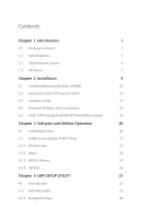
14 2.5 Intel® CNVi (Integrated WiFi/BT) Installation Guide 18 Chapter 3 Software and Utilities Operation 20 3.1 Installing Drivers 20 3.2 ASRock Live Update & APP Shop 21 3.2.1 UI Overview 21 3.2.2 Apps 22 3.2.3 BIOS & Drivers 25 3.2.4 Setting 26 Chapter 4 UEFI SETUP UTILITY 27 - ASRock J4105M | User Manual - Page 5
4.2 Main Screen 29 4.3 Advanced Screen 30 4.3.1 CPU Configuration 31 4.3.2 Chipset Configuration 32 4.3.3 Storage Configuration 34 4.3.4 Super IO Configuration 35 4.3.5 ACPI Configuration 36 4.3.6 USB Configuration 38 4.4 Tools 39 4.5 Hardware Health Event Monitoring Screen 41 - ASRock J4105M | User Manual - Page 6
the latest VGA cards and CPU support list on ASRock's website as well. ASRock website http://www.asrock.com. 1.1 Package Contents • ASRock J4105M / J4005M Motherboard (Micro ATX Form Factor) • ASRock J4105M / J4005M Quick Installation Guide • ASRock J4105M / J4005M Support CD • 2 x Serial ATA (SATA - ASRock J4105M | User Manual - Page 7
design CPU • Intel® Quad-Core Processor J4105 (up to 2.5 GHz) (for J4105M) • Intel® Dual-Core Processor J4005 (up to 2.7 GHz) (for J4005M) Memory • Dual Channel DDR4 Memory Technology • 2 x DDR4 DIMM Slots * 2GB DRAM per module is not supported. • Supports DDR4 2400/2133 non-ECC, un-buffered - ASRock J4105M | User Manual - Page 8
J4105M J4005M • Supports D-Sub with max. resolution up to 2048x1536 @ 60Hz • Supports Auto Lip Sync, xvYCC and HBR (High Bit Rate Audio) with HDMI Port (Compliant HDMI monitor is required) • Supports HDCP with DVI-D and HDMI Ports • Supports driver. • Supports Surge Protection • ELNA Audio Caps LAN • - ASRock J4105M | User Manual - Page 9
x 24 pin ATX Power Connector • 1 x Front Panel Audio Connector • 3 x USB 2.0 Headers (Support 5 USB 2.0 ports) (Supports ESD Protection) • 1 x USB 3.1 Gen1 Header (Supports 2 USB 3.1 Gen1 ports) (Supports ESD Protection) BIOS Feature • AMI UEFI Legal BIOS with GUI support • Supports Plug and Play - ASRock J4105M | User Manual - Page 10
1.3 Motherboard Layout 12 1 CLRMOS1 CPU_FAN1 J4105M J4005M 3 CMOS Battery PS2 Mouse PS2 Keyboard VGA1 BIOS ROM AT X P W R 1 DDR4_A1 (64 bit, 288-pin module) DDR4_A2 (64 bit, 288-pin module) DVI1 4 HDMI1 USB 3.1 Gen1 T: USB0 B: USB1 Top: LINE IN Center: FRONT - ASRock J4105M | User Manual - Page 11
No. Description 1 Clear CMOS Jumper (CLRMOS1) 2 CPU Fan Connector (CPU_FAN1) 3 2 x 288-pin DDR4 DIMM Slots (DDR4_A1, DDR4_A2) 4 ATX Power Connector (ATXPWR1) 5 SATA3 Connector (SATA3_1) 6 SATA3 Connector (SATA3_2) 7 USB 3.1 Gen1 Header (USB3_1_2) 8 System Panel Header (PANEL1) 9 Chassis Fan - ASRock J4105M | User Manual - Page 12
1.4 I/O Panel 1 J4105M J4005M 3 2 4 11 10 No. Description 1 PS/2 Mouse Port 2 LAN RJ-45 Port* 3 Line In (Light Blue)** 4 Front Speaker (Lime)** 5 Microphone (Pink)** 6 USB 2.0 Ports (USB01) 9 8 7 6 5 No. - ASRock J4105M | User Manual - Page 13
7.1 CH HD Audio, it is required to use an HD front panel audio module and enable the multichannel audio feature through the audio driver. Please set Speaker Configuration to "7.1 Speaker"in the Realtek HD Audio Manager. Function of the Audio Ports in 7.1-channel Configuration: Port Light Blue - ASRock J4105M | User Manual - Page 14
it. Pre-installation Precautions Take note of the following precautions before you install motherboard components or change any motherboard settings. • Make sure to unplug the power cord before installing or removing the motherboard. Failure to do so may cause physical injuries to you and damages to - ASRock J4105M | User Manual - Page 15
provides two 288-pin DDR4 (Double Data Rate 4) DIMM slots, and supports Dual Channel Memory Technology. 1. It is not allowed to install a DDR, DDR2 or DDR3 memory module into a DDR4 slot; otherwise, this motherboard and DIMM may be damaged. 2. The DIMM only fits in one correct orientation - ASRock J4105M | User Manual - Page 16
J4105M J4005M 1 2 3 11 English - ASRock J4105M | User Manual - Page 17
slots on the motherboard. Before installing an expansion card, please make sure that the power supply is switched off or the power cord is unplugged. lane width cards. Warning: To ensure better graphics compability, the BIOS is set to "boot from Onboard VGA" as default even the user install a VGA - ASRock J4105M | User Manual - Page 18
J4105M J4005M 2.3 Jumpers Setup The illustration power supply. After waiting for 15 seconds, use a jumper cap to short pin2 and pin3 on CLRMOS1 for 5 seconds. However, please do not clear the CMOS right after you update the BIOS. If you need to clear the CMOS when you just finish updating the BIOS - ASRock J4105M | User Manual - Page 19
jumper caps over the headers and connectors will cause permanent damage to the motherboard. System Panel Header (9-pin PANEL1) (see p.5, No. 8) PLED+ PLEDPWRBTN# GND 1 GND RESET# GND HDLEDHDLED+ Connect the power switch, reset switch and system status indicator on the chassis to this header - ASRock J4105M | User Manual - Page 20
J4105M J4005M Serial ATA3 Connectors (SATA3_1: see p.5, No. 5) (SATA3_2: see p.5, No. 6) SATA3_1 SATA3_2 These two SATA3 connectors support SATA data cables for internal storage devices is one header on this motherboard. This USB 3.1 Gen1 header can support two ports. 1 Vbus - ASRock J4105M | User Manual - Page 21
wire on the chassis must support HDA to function correctly. Please follow the instructions in our manual and chassis manual to install your system. 2. This motherboard provides a 24-pin ATX power connector. To use a 20-pin ATX power supply, please plug it along Pin 1 and Pin 13. This header supports - ASRock J4105M | User Manual - Page 22
J4105M J4005M Print Port Header (25-pin LPT1) (see p.5, No. 14) STB# SPD0 SPD1 SPD2 SLCT PE BUSY SPD3 SPD4 SPD5 ACK# SPD6 SPD7 1 GND SLIN# PINIT# ERROR# AFD# This is an interface for print port cable that allows convenient connection of printer devices. English 17 - ASRock J4105M | User Manual - Page 23
2.5 Intel® CNVi (Integrated WiFi/BT) Installation Guide The M.2, also known as the Next Generation Form Factor (NGFF), is a small size and versatile card edge connector that aims to replace mPCIe and mSATA. The M.2 Socket (Key E) supports type 2230 Intel® CNVi (Integrated WiFi/BT). Installing Intel® - ASRock J4105M | User Manual - Page 24
J4105M J4005M Step 4 Tighten the screw with a screwdriver to secure the module into place. Please do not overtighten the screw as this might damage the module. A 19 English - ASRock J4105M | User Manual - Page 25
Chapter 3 Software and Utilities Operation 3.1 Installing Drivers The Support CD that comes with the motherboard contains necessary drivers and useful utilities that enhance the motherboard's features. Running The Support CD To begin using the support CD, insert the CD into your CD-ROM drive. The CD - ASRock J4105M | User Manual - Page 26
store for purchasing and downloading software applications for your ASRock computer. You can quickly and easily install various apps and support utilities. With ASRock Live Update & APP Shop, you can optimize your system and keep your motherboard up to date simply with a few clicks. Double-click - ASRock J4105M | User Manual - Page 27
3.2.2 Apps When the "Apps" tab is selected, you will see all the available apps on screen for you to download. Installing an App Step 1 Find the app you want to install. The most recommended app appears on the left side of the screen. The other various apps are shown on the right. Please scroll up - ASRock J4105M | User Manual - Page 28
Step 3 If you want to install the app, click on the red icon J4105M J4005M to start downloading. Step 4 When installation completes, you can find the green "Installed" icon appears on the upper right corner. English To uninstall it, - ASRock J4105M | User Manual - Page 29
Upgrading an App You can only upgrade the apps you have already installed. When there is an available new version for your app, you will find the mark of "New Version" appears below the installed app icon. Step 1 Click on the app icon to see more details. Step 2 Click on the yellow icon to start - ASRock J4105M | User Manual - Page 30
J4105M J4005M 3.2.3 BIOS & Drivers Installing BIOS or Drivers When the "BIOS & Drivers" tab is selected, you will see a list of recommended or critical updates for the BIOS or drivers. Please update them all soon. Step 1 Please check the item information before update. Click on Step 2 to see more - ASRock J4105M | User Manual - Page 31
3.2.4 Setting In the "Setting" page, you can change the language, select the server location, and determine if you want to automatically run the ASRock Live Update & APP Shop on Windows startup. 26 English - ASRock J4105M | User Manual - Page 32
J4105M J4005M Chapter 4 UEFI SETUP UTILITY 4.1 Introduction This section explains how to use the UEFI SETUP UTILITY to configure your system. You may run the UEFI SETUP UTILITY by pressing or right after you power on the computer, otherwise, the Power-On-Self-Test (POST) will continue - ASRock J4105M | User Manual - Page 33
4.1.2 Navigation Keys Use < > key or < > key to choose among the selections on the menu bar, and use < > key or < > key to move the cursor up or down to select items, then press to get into the sub screen. You can also use the mouse to click your required item. Please check the following - ASRock J4105M | User Manual - Page 34
J4105M J4005M 4.2 Main Screen When you enter the UEFI SETUP UTILITY, the Main screen will appear and display the system overview. J4105M: J4005M: 29 English - ASRock J4105M | User Manual - Page 35
4.3 Advanced Screen In this section, you may set the configurations for the following items: CPU Configuration, Chipset Configuration, Storage Configuration, Super IO Configuration, ACPI Configuration and USB Configuration. Setting wrong values in this section may cause the system to malfunction. 30 - ASRock J4105M | User Manual - Page 36
saving and heat dissipation. CPU C States Support Enable CPU C States Support for power saving. It is recommended to keep C1 and C6 all enabled for better power saving. Enhanced Halt State (C1E) Enable Enhanced Halt State (C1E) for lower power consumption. Intel Turbo Boost Technology Intel Turbo - ASRock J4105M | User Manual - Page 37
DRAM Voltage Use this to configure DRAM Voltage. The default value is [Auto]. Primary Graphics Adapter Select a primary VGA. Share Memory Configure the size of memory that is allocated to the integrated graphics processor when the system boots up. Onboard HD Audio Enable/disable onboard HD audio - ASRock J4105M | User Manual - Page 38
enables/disables the ASPM support. Deep Sleep Configure deep sleep mode for power saving when the computer is shut down. Restore on AC/Power Loss Select the power state after a power failure. If [Power Off] is selected, the power will remain off when the power recovers. If [Power On] is selected - ASRock J4105M | User Manual - Page 39
that will improve SATA disk performance. SATA Aggressive Link Power Management SATA Aggressive Link Power Management allows SATA devices to enter a low power state during periods of inactivity to save power. It is only supported by AHCI mode. Hard Disk S.M.A.R.T. S.M.A.R.T stands for Self-Monitoring - ASRock J4105M | User Manual - Page 40
4.3.4 Super IO Configuration J4105M J4005M Serial Port 1 Enable or disable the Serial port 1. Serial Port Address Select the address of the Serial port. Serial Port 2 Enable or disable the - ASRock J4105M | User Manual - Page 41
ACPI Configuration Suspend to RAM It is recommended to select auto for ACPI S3 power saving. ACPI HPET Table Enable the High Precision Event Timer for better performance and to pass WHQL tests. PS/2 Keyboard Power On Allow the system to be waked up by a PS/2 Keyboard. PCIE Device Power On Allow the - ASRock J4105M | User Manual - Page 42
USB Keyboard/Remote Power On Allow the system to be waked up by an USB keyboard or remote controller. USB Mouse Power On Allow the system to be waked up by an USB mouse. J4105M J4005M English 37 - ASRock J4105M | User Manual - Page 43
4.3.6 USB Configuration Legacy USB Support Enable Legacy USB Support. AUTO option disables legacy support if no USB devices are connected. DISABLE option will keep USB devices available only for EFI applications. 38 English - ASRock J4105M | User Manual - Page 44
device and run Instant Flash to update your UEFI. Internet Flash ASRock Internet Flash downloads and updates the latest UEFI firmware version from our servers for you. Please setup network configuration before using Internet Flash. *For BIOS backup and recovery purpose, it is recommended to plug in - ASRock J4105M | User Manual - Page 45
Network Configuration Use this to configure internet connection settings for Internet Flash. Internet Setting Enable or disable sound effects in the setup utility. UEFI Download Server Select a server to download the UEFI firmware. 40 English - ASRock J4105M | User Manual - Page 46
J4105M J4005M 4.5 Hardware Health Event Monitoring Screen This section allows you to monitor the status of the hardware on your system, including the parameters of the CPU temperature, motherboard options: [Full On], [Automatic Mode] and [Manual]. The default value is [Full On]. Case Open - ASRock J4105M | User Manual - Page 47
are unable to change the settings in the UEFI Setup Utility. Leave it blank and press enter to remove the password. Secure Boot Enable to support Secure Boot. Intel(R) Platform Trust Technology Enable/disable Intel PTT in ME. Disable this option to use discrete TPM Module. 42 English - ASRock J4105M | User Manual - Page 48
J4105M J4005M 4.7 Boot Screen This section displays the available devices on your system for you to configure the boot settings and the boot priority. Fast Boot Fast Boot minimizes your computer's boot time. In fast mode you may not boot from an USB storage device. The VBIOS must support UEFI GOP if - ASRock J4105M | User Manual - Page 49
Full Screen Logo Enable to display the boot logo or disable to show normal POST messages. Boot Failure Guard Message If the computer fails to boot for a number of times the system automatically restores the default settings. 44 English - ASRock J4105M | User Manual - Page 50
4.8 Exit Screen J4105M J4005M Save Changes and Exit When you select this option the following message, "Save configuration changes and exit setup?" will pop out. Select [OK] to - ASRock J4105M | User Manual - Page 51
dealer for further information. For technical questions, please submit a support request form at https://event.asrock.com/tsd.asp ASRock Incorporation 2F., No.37, Sec. 2, Jhongyang S. Rd., Beitou District, Taipei City 112, Taiwan (R.O.C.) ASRock EUROPE B.V. Bijsterhuizen 11-11 6546 AR Nijmegen The - ASRock J4105M | User Manual - Page 52
FCC Part 2 Section 2.1077(a) Responsible Party Name: ASRock Incorporation Address: 13848 Magnolia Ave, Chino, CA91710 Phone/Fax No: +1-909-590-8308/+1-909-590-1026 hereby declares that the product Product Name : Motherboard Model Number : J4105M / J4005M Conforms to the following speci cations: FCC - ASRock J4105M | User Manual - Page 53
EU Declaration of Conformity For the following equipment: Motherboard (Product Name) J4105M / J4005M / ASRock (Model Designation / Trade Name) ASRock Incorporation (Manufacturer Name) 2F., No.37, Sec. 2, Jhongyang S. Rd., Beitou District, Taipei City 112, Taiwan (R.O.C.) (Manufacturer Address)
-
 1
1 -
 2
2 -
 3
3 -
 4
4 -
 5
5 -
 6
6 -
 7
7 -
8
-
9
-
10
-
11
-
12
-
13
-
14
-
15
-
16
-
17
-
18
-
19
-
20
-
21
-
22
-
23
-
24
-
25
-
26
-
27
-
28
-
29
-
30
-
31
-
32
-
33
-
34
-
35
-
36
-
37
-
38
-
39
-
40
-
41
-
42
-
43
-
44
-
45
-
46
-
47
-
48
-
49
-
50
-
51
-
52
-
53
 |
 |