ASRock K10N78 User Manual
ASRock K10N78 Manual
 |
View all ASRock K10N78 manuals
Add to My Manuals
Save this manual to your list of manuals |
ASRock K10N78 manual content summary:
- ASRock K10N78 | User Manual - Page 1
K10N78-1394 / K10N78 User Manual Version 1.1 Published August 2008 Copyright©2008 ASRock INC. All rights reserved. 1 - ASRock K10N78 | User Manual - Page 2
like), even if ASRock has been advised of the possibility of such damages arising from any defect or error in the manual or product. This device complies with Part 15 of the , USA ONLY The Lithium battery adopted on this motherboard contains Perchlorate, a toxic substance controlled in Perchlorate - ASRock K10N78 | User Manual - Page 3
-DVD Playback Support 11 1.4 Passed 1080p Blu-ray (BD) / HD-DVD Films in Our Lab Test ... 12 1.5 Motherboard Layout (K10N78-1394 13 1.6 Motherboard Layout (K10N78 14 1.7 I/O Panel (K10N78-1394 15 1.8 I/O Panel (K10N78 16 2 . Installation 17 Pre-installation Precautions 17 2.1 CPU Installation - ASRock K10N78 | User Manual - Page 4
Health Event Monitoring Screen 68 3.6 Boot Screen 69 3.6.1 Boot Settings Configuration 69 3.7 Security Screen 70 3.8 Exit Screen 71 4 . Software Support 72 4.1 Install Operating System 72 4.2 Support CD Information 72 4.2.1 Running Support CD 72 4.2.2 Drivers Menu 72 4.2.3 Utilities Menu - ASRock K10N78 | User Manual - Page 5
the model you are using. www.asrock.com/support/index.asp 1.1 Package Contents ASRock K10N78-1394 / K10N78 Motherboard (ATX Form Factor: 12.0-in x 8.4-in, 30.5 cm x 21.3 cm) ASRock K10N78-1394 / K10N78 Quick Installation Guide ASRock K10N78-1394 / K10N78 Support CD One 80-conductor Ultra ATA 66 - ASRock K10N78 | User Manual - Page 6
- Supports CPU up to 140W - AMD LIVE!TM Ready - Supports AMD's Cool 'n' QuietTM Technology - FSB 2600 MHz (5.2 GT/s) (see CAUTION 1) - Supports Untied Overclocking Technology (see CAUTION 2) - Supports Hyper-Transport 3.0 (HT 3.0) Technology - NVIDIA® GeForce 8200 - Dual Channel DDR2 Memory - ASRock K10N78 | User Manual - Page 7
Connector BIOS Feature Support CD I/O Panel - 1 x PS/2 Mouse Port - 1 x PS/2 Keyboard Port - 1 x VGA/D-Sub Port - 1 x VGA/DVI-D Port - 6 x Ready-to-Use USB 2.0 Ports - 1 x eSATAII Port (K10N78-1394) - 1 x RJ-45 LAN Port with LED (ACT/LINK LED and SPEED LED) - 1 x IEEE 1394 Port (K10N78-1394) - HD - ASRock K10N78 | User Manual - Page 8
frequency depends on the ability of the AM2+ CPU you adopt. Please refer to the CPU support list on our website for more information. ASRock website http://www.asrock.com 2. This motherboard supports Untied Overclocking Technology. Please read "Untied Overclocking Technology" on page 50 for details - ASRock K10N78 | User Manual - Page 9
actual memory size may be less than 4GB for the reservation for system usage under Windows® XP and Windows® VistaTM. For Windows® XP 64-bit and Windows® VistaTM 64bit with 64-bit CPU, there is no such limitation. 6. Hybrid SLITM feature should depend on the driver from NVIDIA® and it may be updated - ASRock K10N78 | User Manual - Page 10
dissipation, remember to spray thermal grease between the CPU and the heatsink when you install the PC system. 18. This motherboard supports ASRock AM2 Boost overclocking technology for AM2 CPU. If you enable this function in the BIOS setup, the memory performance will improve up to 12.5%, but the - ASRock K10N78 | User Manual - Page 11
-ray (BD) / HD-DVD Playback Support 1080p Blu-ray (BD) / HD-DVD playback support on this motherboard requires the proper hardware configuration. Please refer to below table for the minimum hardware requirement. CPU VGA Memory Suggested OS AMD Phenom X3 8400 Onboard VGA with DVI-D port Dual Channel - ASRock K10N78 | User Manual - Page 12
1.4 Passed 1080p Blu-ray (BD) / HD-DVD Films in Our Lab Test DVD Type Blu-ray DVD under below configuration. Items Configurations CPU AMD Phenom X3 8400 VGA Onboard VGA with DVI-D port Memory Dual Channel DDR2 533, 1GB x 2 OS Windows® VistaTM or Windows® VistaTM 64 Playback Software - ASRock K10N78 | User Manual - Page 13
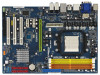
USB/WIFI HD_AUDIO1 CD1 1 IR1 1 FLOPPY1 PCIE1 K10N78-1394 CLRCMOS1 1 CMOS BATTERY SATAII_1 (PORT0) SATAII_3 (PORT2) SATAII_5 (PORT4) SATAII_2 (PORT1) SATAII_4 (PORT3) SATAII_6 (PORT5) PCI1 RoHS PCI2 PCI3 NVIDIA GeForce 8200 Chipset CHA_FAN1 SPEAKER1 1 PANEL 1 PLED PWRBTN 1 HDLED RESET 8Mb - ASRock K10N78 | User Manual - Page 14
PCI3 NVIDIA GeForce 8200 Chipset CHA_FAN1 SPEAKER1 1 PANEL 1 PLED PWRBTN 1 HDLED RESET 8Mb BIOS USB8_9 1 1 USB6_7 30.5cm (12.0-in) 8 9 10 11 12 13 14 26 25 24 23 22 21 20 19 1817 16 15 1 PS2_USB_PW1 Jumper 2 ATX 12V Power Connector (ATX12V1) 3 CPU Fan Connector (CPU_FAN1) 4 CPU Heatsink - ASRock K10N78 | User Manual - Page 15
I/O Panel (K10N78-1394) 1 2 34 5 6 9 7 10 8 11 16 15 14 1 PS/2 Mouse Port (Green) 2 VGA/D-Sub Port 3 USB 2.0 Ports (USB45) 4 IEEE 1394 Port * connection Blinking Data Activity Orange 100Mbps connection Green 1Gbps connection LAN Port ** If you use 2-channel speaker, please connect - ASRock K10N78 | User Manual - Page 16
1.7 I/O Panel (K10N78) 1 2 3 4 7 2.0 Ports (USB23) 12 USB 2.0 Ports (USB45) 13 VGA/DVI-D Port 14 PS/2 Keyboard Port (Purple) * There are two LED enable Multi-Streaming function, you need to connect a front panel audio cable to the front panel audio header. After restarting your computer, you - ASRock K10N78 | User Manual - Page 17
ATX form factor (12.0-in x 8.4-in, 30.5 cm x 21.3 cm) motherboard. Before you install the motherboard, study the configuration of your chassis to ensure that the motherboard following precautions before you install motherboard components or change any motherboard settings. Before you install or - ASRock K10N78 | User Manual - Page 18
. Make sure that the CPU and the heatsink are securely fastened and in good contact with each other. Then connect the CPU fan to the CPU FAN connector (CPU_FAN1, see Page 13/14, No. 3). For proper installation, please kindly refer to the instruction manuals of the CPU fan and the heatsink. 18 - ASRock K10N78 | User Manual - Page 19
color. In other words, install them either in the set of yellow slots (DDRII_1 and DDRII_2), or in the set of orange slots (DDRII_3 and DDRII_4). 2. If only one memory module or three memory modules are installed in the DDR2 DIMM slots on this motherboard, it is unable to activate the Dual Channel - ASRock K10N78 | User Manual - Page 20
matches the break on the slot. notch break notch break The DIMM only fits in one correct orientation. It will cause permanent damage to the motherboard and the DIMM if you force the DIMM into the slot at incorrect orientation. Step 3. Firmly insert the DIMM into the slot until the retaining - ASRock K10N78 | User Manual - Page 21
is unplugged. Please read the documentation of the expansion card and make necessary hardware settings for the card before you start the installation. Step 2. Remove the system unit cover (if your motherboard is already installed in a chassis). Step 3. Remove the bracket facing the slot that you - ASRock K10N78 | User Manual - Page 22
is only supported with Windows® VistaTM OS, and is not available with other OS. Please visit our website for the driver update in the future. GeForce® Boost GeForce® Boost turbocharges the performance of NVIDIA® discrete GPU when combined with NVIDIA® motherboard GPU. When GeForce® Boost is - ASRock K10N78 | User Manual - Page 23
® Boost and HybridPowerTM features are supported only with certain set of discrete GPUs. Please refer to our website for the graphics cards update in the future. For GeForce® Boost Vendor Chipset NVIDIA GeForce 8400GS GeForce 8400GS GeForce 8400GS GeForce 8500GT Model Gigabyte GV-NX84G256H Foxconn - ASRock K10N78 | User Manual - Page 24
. Step 5. Connect the monitor cable to the correspondent connector on the I/O shield. Step 6. Boot into OS. Install Hybrid SLITM driver from our support CD to your system. Hybrid SLITM driver is in the following path of ASRock support CD: (There are two ASRock support CD in the motherboard gift box - ASRock K10N78 | User Manual - Page 25
connector on the I/O shield. Connect the other monitor cable to the correspondent connector on the PCI Express graphics card on PCIE1 slot. Step 4. Boot into OS. Install Hybrid SLITM driver from our support CD to your system. Hybrid SLITM driver is in the following path of ASRock support CD: (There - ASRock K10N78 | User Manual - Page 26
the below steps: 1. Connect the DVI-D monitor cable to the VGA/DVI-D port on the I/O panel of this motherboard. Connect the D-Sub monitor cable to the VGA/D-Sub port on the I/O panel of this motherboard. VGA/D-Sub port VGA/DVI-D port 2. If you have installed onboard VGA driver from our support CD to - ASRock K10N78 | User Manual - Page 27
-D monitor cable to the VGA/DVI-D port on the I/O panel of this motherboard. Connect the D-Sub monitor cable to the VGA/D-Sub port on the I/O panel of this motherboard. 3. Boot your system. Press to enter BIOS setup. Enter "Share Memory" option to adjust the memory capability to [32MB], [64MB - ASRock K10N78 | User Manual - Page 28
is supported with DVI-D port on this motherboard. To use HDCP function with this motherboard, you need to adopt the monitor that supports HDCP function as well. Therefore, you can enjoy the superior display quality with high-definition HDCP encryption contents. Please refer to below instruction for - ASRock K10N78 | User Manual - Page 29
/ XP 64-bit OS Step 1: Set up BIOS. A. Enter BIOS SETUP UTILITY Advanced screen Chipset Configuration. B. Set the option "OnBoard HDMI HD Audio" to [Auto]. Step 2: Install HDMI audio driver to your system. Install "Onboard HDMI HD Audio Driver" from ASRock Support CD to your system. Step 3: Reboot - ASRock K10N78 | User Manual - Page 30
and pin2 are "Short" when jumper cap is placed on these 2 pins. Jumper Setting PS2_USB_PW1 1_2 2_3 Short pin2, pin3 to enable (see p.13/14, No. 1) CMOS right after you update the BIOS. If you need to clear the CMOS when you just finish updating the BIOS, you must boot up the system first - ASRock K10N78 | User Manual - Page 31
IDE1 connect the blue end to the motherboard connect the black end to the IDE devices 80-conductor ATA 66/100/133 cable Note: Please refer to the instruction of For K10N78-1394, SATAII_6 (PORT5) connector can be used for internal storage device or be connected to eSATAII connector to support - ASRock K10N78 | User Manual - Page 32
eSATAII connector supports SATA data cable for external SATAII function. The current eSATAII interface allows up to 3.0 Gb/s data transfer rate. Either end of the SATA data cable can be connected to the SATA / SATAII hard disk or the SATAII connector on this motherboard. For K10N78-1394, you can - ASRock K10N78 | User Manual - Page 33
and OUT_RET are for HD audio panel only. You don't need to connect them for AC'97 audio panel. E. Enter BIOS Setup Utility. Enter Advanced Settings, and then select Chipset Configuration. Set the Front Panel Control option from [Auto] to [Enabled]. F. Enter Windows system. Click the icon - ASRock K10N78 | User Manual - Page 34
fan (Quiet Fan) support, the 3-Pin CPU fan still can work successfully even without the fan speed control function. If you plan to connect the 3-Pin CPU fan to the CPU fan connector on this motherboard, please connect it to Pin 1-3. Pin 1-3 Connected 3-Pin Fan Installation ATX Power Connector (24 - ASRock K10N78 | User Manual - Page 35
1 +12V RXTPBP_0 GND RXTPAP_0 This COM1 header supports a serial port module. Besides one default IEEE 1394 port on the I/O panel, there is one IEEE 1394 header (FRONT_1394) on this motherboard. This IEEE 1394 header can support one IEEE 1394 port. i HDMI_SPDIF Header HDMI_SPDIF header, providing - ASRock K10N78 | User Manual - Page 36
the black end (A) of HDMI_SPDIF cable to the HDMI_SPDIF header on the motherboard. Then connect the white end (B or C) of HDMI_SPDIF cable to the HDMI_SPDIF connector of HDMI VGA card. A. black end +5V SPDIFOUT GND B. white end (2-pin) C. white end (3- - ASRock K10N78 | User Manual - Page 37
definition of HDMI_SPDIF connectors on HDMI VGA card, please refer to the user manual of HDMI VGA card vendor. Incorrect connection may cause permanent damage to this motherboard and the HDMI VGA card. Step 3. Connect the white end (B or C) of HDMI_SPDIF cable to the HDMI_SPDIF connector of HDMI - ASRock K10N78 | User Manual - Page 38
eSATAII Interface Introduction (Only for K10N78-1394) What is eSATAII? This motherboard supports eSATAII interface, the external SATAII IEEE 1394 to be a trend for external interface. NOTE: 1. If you set "SATA Operation Mode" option in BIOS setup to AHCI or RAID mode, Hot Plug function is supported - ASRock K10N78 | User Manual - Page 39
How to install eSATAII? SATAII_6 (PORT5) eSATAII_TOP 1. In order to enable the eSATAII port of the I/O shield, you need to connect the orange SATAII connector (SATAII_6 (PORT5); see p.13/14 No.11) and the eSATAII connector (eSATAII_TOP; see p.13 No.36 or p.14 No.35) with a - ASRock K10N78 | User Manual - Page 40
Comparison between eSATAII and other devices IEEE 1394 USB 2.0 SATA eSATAII/SATAII 400Mb/s 480Mb/s 1.5Gb/s (1500Mb/s) 3.0Gb/s (3000Mb/s) 40 - ASRock K10N78 | User Manual - Page 41
guide. Some default setting of SATAII hard disks may not be at SATAII mode, which operate with the best performance. In order to enable SATAII function, please follow the below instruction 's website for details: http://www.hitachigst.com/hdd/support/download.htm The above examples are just for your - ASRock K10N78 | User Manual - Page 42
motherboard adopts NVIDIA® GeForce 8200 chipset that supports Serial ATA (SATA) / Serial ATAII (SATAII) hard disks and RAID functions. You may install SATA / SATAII hard disks on this motherboard for internal storage devices. This section will guide disks. 2. For K10N78-1394, it is recommended to - ASRock K10N78 | User Manual - Page 43
motherboard supports Hot Plug and Hot Swap functions for SATA / SATAII / eSATAII Devices in RAID / AHCI mode. NVIDIA® GeForce 8200 chipset provides hardware support the system is still power-on and in working condition. For K10N78-1394, eSATAII is equipped with Hot Plug capability that enables you to - ASRock K10N78 | User Manual - Page 44
is installed into system properly. The latest SATA / SATAII driver is available on our support website: www.asrock.com 4. Make sure to use the SATA power cable & data cable, which are from our motherboard package. 5. Please follow below instructions step by step to reduce the risk of HDD crash or - ASRock K10N78 | User Manual - Page 45
follow below instruction sequence to process the Hot Plug, improper procedure will cause the SATA / SATAII HDD damage and data loss. Step 1 Please connect SATA power cable 1x4-pin end Step 2 Connect SATA data cable to (White) to the power supply 1x4-pin cable. the motherboard's SATAII connector - ASRock K10N78 | User Manual - Page 46
A. Enter BIOS SETUP UTILITY Advanced screen IDE Configuration. B. Set the "SATA Operation Mode" option to [IDE]. STEP 2: Make a SATA / SATAII driver diskette. A. Insert the ASRock Support CD into your optical drive to boot your system. (There are two ASRock Support CD in the motherboard gift - ASRock K10N78 | User Manual - Page 47
optical drive to boot your system, and follow the instruction to install Windows® VistaTM / Windows® VistaTM 64-bit OS on your system. When you see "Where do you want to install Windows? " page, please insert the ASRock Support CD into your optical drive, and click the "Load Driver" button on - ASRock K10N78 | User Manual - Page 48
" to [RAID]. STEP 4: Use "RAID Installation Guide" to set RAID configuration. Before you start to configure RAID function, you need to check the RAID installation guide in the Support CD for proper configuration. Please refer to the BIOS RAID installation guide part of the document in the following - ASRock K10N78 | User Manual - Page 49
, please insert the ASRock Support CD into your optical drive, and click the "Load Driver" button on the left on the bottom to load the NVIDIA® RAID drivers. NVIDIA® RAID drivers are in the following path in our Support CD: (There are two ASRock Support CD in the motherboard gift box pack, please - ASRock K10N78 | User Manual - Page 50
Mode" to [RAID] in BIOS first. Then, please set the RAID configuration by using the Windows RAID installation guide in the following path in the Support CD: .. \ RAID Installation Guide 2.19 Untied Overclocking Technology This motherboard supports Untied Overclocking Technology, which means during - ASRock K10N78 | User Manual - Page 51
the BIOS SETUP UTILITY to configure your system. The Flash Memory on the motherboard stores the BIOS SETUP UTILITY. You may run the BIOS SETUP UTILITY set up the system time/date information Advanced To set up the advanced BIOS features H/W Monitor To display current hardware status Boot To set - ASRock K10N78 | User Manual - Page 52
-1394 BIOS SETUP UTILITY Main Smart Advanced H/W Monitor Boot Security Exit System Overview System Time System Date [14:00:09] [Fri 07/25/2008] BIOS Version : K10N78-1394 P1.00 Processor Type : AMD Phenom (tm) 9750 Quad-Core Processor (64bit) Processor Speed : 2400MHz Microcode Update - ASRock K10N78 | User Manual - Page 53
UTILITY Main Smart Advanced H/W Monitor Boot Security Exit System Overview System Time System Date [14:00:09] [Fri 07/25/2008] BIOS Version : K10N78 P1.00 Processor Type : AMD Phenom (tm) 9750 Quad-Core Processor (64bit) Processor Speed : 2400MHz Microcode Update : 100F23/1000065 L1 Cache - ASRock K10N78 | User Manual - Page 54
, IDE Configuration, PCIPnP Configuration, Floppy Configuration, SuperIO Configuration, and USB Configuration. BIOS SETUP UTILITY Main Smart Advanced H/W Monitor Boot Security Exit Advanced Settings Options for CPU WARNING : Setting wrong values in below sections may cause system to malfunction - ASRock K10N78 | User Manual - Page 55
only when you adopt AM2 CPU. If you set this option to [Enabled], you will enable ASRock AM2 Boost function, which will improve the memory performance. The default value is [Disabled]. Please refer to caution 18 on page 10 for details. Overclock Mode Use this to select Overclock Mode. The default - ASRock K10N78 | User Manual - Page 56
Processor Frequency This option appears only when you adopt AM2 CPU. This item will show when "Multiplier/Voltage Change" is set to [Manual]; otherwise, it will be hidden. The range of the value depends on the CPU you adopt on this motherboard. However, for system stability, it is not recommended to - ASRock K10N78 | User Manual - Page 57
Processor Voltage This option appears only when you adopt AM2 CPU. This item will show when "Multiplier/Voltage Change" is set to [Manual]; otherwise, it will be hidden. The range of the value depends on the CPU you adopt on this motherboard. However, for safety and system stability, it is not - ASRock K10N78 | User Manual - Page 58
tolerance for memory compatibility when it is set to [Enabled]. Memory Controller Mode Use this item to adjust memory controller mode. The default value is [Auto]. TRWTTO This option appears only when you adopt AM2 CPU. Use this to adjust TRWTTD values. Configuration options: [Auto], [2CLK], [3CLK - ASRock K10N78 | User Manual - Page 59
This option appears only when you adopt AM2 CPU. Use this to adjust TRWTTD values. Configuration BIOS SETUP UTILITY Advanced Chipset Settings Onboard LAN Onboard 1394 Onboard HDMI HD Audio Onboard HD Audio Front Panel CD-In Hybrid SLI Share Memory Primary Graphics Adapter CPU - NB Link Speed CPU - ASRock K10N78 | User Manual - Page 60
motherboard to support Hybrid SLITM function. You are allowed to select this option only when the total capacity of the memory module you adopt is 1GB and above. If you install non-NVIDIA clock will be in overclocking mode. [Manual] - If you adopt NVIDIA® graphics card and select [Manual], the item " - ASRock K10N78 | User Manual - Page 61
2600 MHz]. The configuration options depend on the CPU you adopt. CPU - NB Link Width This feature allows you selecting CPU to NB link width. Configuration options: [ Core Clock This option only appears when you set the option "Onboard GPU Clock" to [Manual]. This allows you to adjust onboard GPU - ASRock K10N78 | User Manual - Page 62
3.4.3 ACPI Configuration BIOS SETUP UTILITY Advanced ACPI Settings Suspend To RAM Repost Video on STR Resume Check Ready Bit Away Mode Support Restore on AC / Power Loss Ring-In Power On PCI Devices Power On PS / 2 Keyboard Power On RTC Alarm Power On ACPI HPET Table [Auto] [ - ASRock K10N78 | User Manual - Page 63
set this option to [Enabled] if you plan to use this motherboard to submit Windows® VistaTM certification. 3.4.4IDE Configuration BIOS / SATAII HDDs, please select [RAID]. If you want to enable eSATAII function on K10N78-1394, please select [RAID] or [AHCI]. Configuration options: [RAID], [IDE] and - ASRock K10N78 | User Manual - Page 64
Supported :16Sectors :4 :MultiWord DMA-2 :Ultra DMA-6 :Supported Type LBA/Large Mode Block (Multi-Sector Transfer) PIO Mode DMA Mode S.M.A.R.T. 32Bit Data Transfer [Auto] [Auto] [Auto] [Auto] [Auto] [Disabled] [Disabled] Select the type of device connected into BIOS, use MB under DOS and Windows set - ASRock K10N78 | User Manual - Page 65
Data Transfer Use this item to enable 32-bit access to maximize the IDE hard disk data transfer rate. 3.4.5 PCIPnP Configuration BIOS SETUP UTILITY Advanced Advanced PCI / PnP Settings PCI Latency Timer PCI IDE BusMaster [32] [Enabled] Value in units of PCI clocks for PCI device latency timer - ASRock K10N78 | User Manual - Page 66
drive. BIOS SETUP UTILITY Advanced Floppy Configuration Floppy A [1.44 MB 312"] Select the type of floppy drive connected to the enable or disable floppy drive controller. Serial Port Address Use this item to set the address for the onboard serial port or disable it. Configuration options: [ - ASRock K10N78 | User Manual - Page 67
descriptions for the details of these four options: [Enabled] - Enables support for legacy USB. [Auto] - Enables legacy support if USB devices are connected. [Disabled] - USB devices are not allowed to use under legacy OS and BIOS setup when [Disabled] is selected. If you have USB compatibility - ASRock K10N78 | User Manual - Page 68
including the parameters of the CPU temperature, motherboard temperature, CPU fan speed, chassis fan speed, and the critical voltage. BIOS SETUP UTILITY Main Smart Advanced H/W Monitor Boot Security Exit Hardware Health Event Monitoring CPU Temperature M / B Temperature CPU Fan Speed Chassis Fan - ASRock K10N78 | User Manual - Page 69
F10 Save and Exit ESC Exit v02.54 (C) Copyright 1985-2005, American Megatrends, Inc. 3.6.1 Boot Settings Configuration BIOS SETUP UTILITY Boot Boot Settings Configuration Full Screen Logo AddOn ROM Display Boot Logo Boot From Onboard LAN Bootup Num-Lock [Enabled] [Enabled] [Auto] [Disabled] [On - ASRock K10N78 | User Manual - Page 70
Full Screen Logo". Configuration options: [Auto], [PCIE2.0 Revolution], [Scenery] and [ASRock]. The default value is [Auto]. Currently, the option [Auto] is set to Aircraft. Boot clear it. BIOS SETUP UTILITY Main Smart Advanced H/W Monitor Boot Security Exit Security Settings Supervisor Password : - ASRock K10N78 | User Manual - Page 71
3.8 Exit Screen BIOS SETUP UTILITY Main Smart Advanced H/W Monitor Boot Security Exit Exit Options Save Changes and Exit Discard Changes and Exit Discard Changes Would you like to save current setting user defaults ? Save 1st User Defaults Load 1st User Defaults Save 2nd User Defaults Load 2nd - ASRock K10N78 | User Manual - Page 72
64-bit. Because motherboard settings and hardware options vary, use the setup procedures in this chapter for general reference only. Refer to your OS documentation for more information. 4.2 Support CD Information The Support CD that came with the motherboard contains necessary drivers and useful
-
 1
1 -
 2
2 -
 3
3 -
 4
4 -
 5
5 -
 6
6 -
 7
7 -
8
-
9
-
10
-
11
-
12
-
13
-
14
-
15
-
16
-
17
-
18
-
19
-
20
-
21
-
22
-
23
-
24
-
25
-
26
-
27
-
28
-
29
-
30
-
31
-
32
-
33
-
34
-
35
-
36
-
37
-
38
-
39
-
40
-
41
-
42
-
43
-
44
-
45
-
46
-
47
-
48
-
49
-
50
-
51
-
52
-
53
-
54
-
55
-
56
-
57
-
58
-
59
-
60
-
61
-
62
-
63
-
64
-
65
-
66
-
67
-
68
-
69
-
70
-
71
-
72
 |
 |
1
K10N78-1394
/ K10N78
User Manual
Version 1.1
Published August 2008
Copyright©2008 ASRock INC. All rights reserved.