ASRock K7Upgrade-600 User Manual
ASRock K7Upgrade-600 Manual
 |
View all ASRock K7Upgrade-600 manuals
Add to My Manuals
Save this manual to your list of manuals |
ASRock K7Upgrade-600 manual content summary:
- ASRock K7Upgrade-600 | User Manual - Page 1
MOTHERBOARD K7Upgrade-600 User Manual Version 1.1 Published August 2004 Copyright©2004 ASRock INC. All rights reserved. 1 - ASRock K7Upgrade-600 | User Manual - Page 2
backup purpose, without written consent of ASRock Inc. Products and corporate names appearing in this manual may or may not be registered trademarks benefit, without intent to infringe. Disclaimer: Specifications and information contained in this manual are furnished for informational use only and - ASRock K7Upgrade-600 | User Manual - Page 3
Hot Swap Functions for SATA HDDs .......... 20 2.9 Making An SATA Driver Diskette 21 3. BIOS Setup (K7Upgrade-600 22 3.1 BIOS Setup Utility 22 3.1.1 BIOS Menu Bar 22 3.1.2 Legend Bar 22 3.2 Main Menu 23 3.3 Advanced, Security, Power, Boot, and Exit Menus 26 3.3.1. Advanced BIOS Setup Menu 26 - ASRock K7Upgrade-600 | User Manual - Page 4
Screen 46 4.5 Boot Screen 46 4.5.1 Boot Settings Configuration 47 4.5.2 Boot Device Priority 47 4.6 Security Screen 48 4.7 Exit Screen 48 5. Software Support 50 5.1 Install Operating System 50 5.2 Support CD Information 50 5.2.1 Running Support CD 50 5.2.2 Drivers Menu 50 5.2.3 Utilities - ASRock K7Upgrade-600 | User Manual - Page 5
the latest memory and CPU support lists on ASRock website as well. ASRock website http://www.asrock.com 1.1 Package Contents ASRock K7Upgrade-600 Motherboard (ATX Form Factor: 12.0-in x 8.2-in, 30.5 cm x 20.8 cm) ASRock K7Upgrade-600 Quick Installation Guide ASRock K7Upgrade-600 Support CD One 80 - ASRock K7Upgrade-600 | User Manual - Page 6
1.2 Specifications Platform: CPU: ATX Form Factor: 12.0-in x 8.2-in, 30.5 cm x 20.8 cm 462-Pin Socket Supporting AMD AthlonTM / AthlonTM XP / DuronTM / 32-bit SempronTM Processor Chipsets: North Bridge: VIA KT600, FSB @ 400 MHz South Bridge: VIA VT8237, supports USB 2.0, ATA 133, SATA 1.5Gb/s - ASRock K7Upgrade-600 | User Manual - Page 7
, 4 ready-to-use USB 2.0 ports, 1 RJ-45 port, Audio Jack: Line In / Line Out / Microphone AMI BIOS Supports "Plug and Play" ACPI 1.1 compliance wake up events SMBIOS 2.3.1 support CPU frequency stepless control (only for advanced users' reference, see CAUTION 4) Microsoft® Windows® 98SE / ME / 2000 - ASRock K7Upgrade-600 | User Manual - Page 8
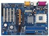
1 4Mb BIOS PCI LAN Audio CODEC JR1 JL1 IR1 AUDIO1 1 1 FLOPPY1 AGP 8X IDE1 IDE2 1.5V_AGP1 Clock Gen K8BRIDGE_1 FSB400 J4 1 K8BRIDGE_2 1 J5 J9 J8 J7 AGP2 PCI 1 PCI 2 K7Upgrade-600 VIA VT8237 1 FSB_SEL0 1 FSB_SEL1 FSB_SEL2 1 J13 J11 J16 PCI 3 PCI 4 ATA133 SATA USB2.0 5.1 CH - ASRock K7Upgrade-600 | User Manual - Page 9
1.4 ASRock I/OTM 1 2 3 10 9 8 1 Parallel Port 2 RJ-45 Port 3 Game Port 4 Microphone (Pink) 5 Line In (Light Blue) 7 654 6 Line Out (Lime) 7 USB 2.0 Ports 8 Serial Port (COM1) 9 PS/2 Keyboard Port (Purple) 10 PS/2 Mouse Port (Green) 9 - ASRock K7Upgrade-600 | User Manual - Page 10
2. Installation K7Upgrade-600 is an ATX form factor (12.0-in x 8.2-in, 30.5 cm x 20.8 cm) motherboard. Before you install the motherboard, study the configuration of your chassis to ensure that the motherboard fits into it. Pre-installation Precautions Take note of the following precautions before - ASRock K7Upgrade-600 | User Manual - Page 11
, press it firmly on the socket while you push down the socket lever to secure the CPU. The lever clicks on the side tab to indicate that it is locked. Step 1 Step 2, 3 Step 4 2.2 Installation of CPU Fan and Heatsink After you install the CPU into this motherboard, it is necessary to install - ASRock K7Upgrade-600 | User Manual - Page 12
2.3 Installation of Memory Modules (DIMM) K7Upgrade-600 motherboard provides two 184-pin DDR (Double Data Rate break The DIMM only fits in one correct orientation. It will cause permanent damage to the motherboard and the DIMM if you force the DIMM into the slot at incorrect orientation. Step 3. - ASRock K7Upgrade-600 | User Manual - Page 13
the slot AGP2 supports for K8 AGP Interface) on K7Upgrade-600 motherboard. K8 Bridge (Orange-Colored Bridge (K8BRIDGE_1) + Brown-Colored Bridge (K8BRIDGE_2)): The set of K8 Bridge allows you to upgrade your AMD 462-Pin CPU to AMD 754-Pin CPU by installing an add-on ASRock 754Bridge (optional) into - ASRock K7Upgrade-600 | User Manual - Page 14
motherboard package, and please follow the "Jumper Cap Remover Instruction" to use it properly. PCI slots: PCI slots are used to install expansion cards a graphics card. Please insert the AGP card with K7 AGP Interface into the slot 1.5V_AGP1 (see page 8 No. 33), or insert the AGP card with K8 AGP - ASRock K7Upgrade-600 | User Manual - Page 15
FSB 266MHz FSB 333MHz FSB 400MHz Note: The setting of the CPU front side bus frequency of this motherboard is by means of the adjustment of jumper-setting. To perform over clocking, you must set the FSB jumper according to your AMD CPU before you use the "Manual" option as the FSB setting in BIOS - ASRock K7Upgrade-600 | User Manual - Page 16
The jumper caps are not provided by ASRock. Please understand that ASRock does not guarantee and support the adjustment of multiplier. These jumpers setting may not apply to all multiplier-locked or even some unlocked AMD CPU. Frequencies other than the recommended CPU bus frequencies may cause the - ASRock K7Upgrade-600 | User Manual - Page 17
connectors support SATA data cables for internal storage SATA1 devices. The current SATA interface allows up to 1.5 Gb/s data transfer rate. Serial ATA (SATA) Data Cable Either end of the SATA data cable can be connected to the SATA hard disk or the SATA connector on the motherboard. 17 - ASRock K7Upgrade-600 | User Manual - Page 18
the white end of SATA power cable to the power connector of the power supply. ASRock I/O provides you 4 ready-to-use USB 2.0 ports on the rear panel. If the rear USB ports are not sufficient, this USB 2.0 header is available to support 4 extra USB 2.0 ports. ASRock I/O provides you 4 ready-to - ASRock K7Upgrade-600 | User Manual - Page 19
Fan Connector (3-pin CHA_FAN1) (see p.8, No. 19) CHA_FAN_SPEED +12V GND CPU Fan Connector (3-pin CPU_FAN1) (see p.8, No. 2) ATX Power Connector (20 and match the black wire to the ground pin. Please connect the CPU fan cable to this connector and match the black wire to the ground pin. - ASRock K7Upgrade-600 | User Manual - Page 20
Connect one end of the SATA data cable to the motherboard's SATA connector. STEP 4: Connect the other end of the SATA data cable to the SATA hard disk. 2.8 Hot Plug and Hot Swap Functions for SATA HDDs K7Upgrade-600 motherboard supports Hot Plug and Hot Swap functions for SATA Devices. What is Hot - ASRock K7Upgrade-600 | User Manual - Page 21
Diskette If you want to install Windows 2000 or Windows XP on your SATA HDDs, you will need to make an SATA driver diskette before you start the OS installation. STEP 1: Insert the ASRock Support CD into your optical drive to boot your system. (Do NOT insert any floppy diskette into the floppy - ASRock K7Upgrade-600 | User Manual - Page 22
BIOS Setup (K7Upgrade-600) 3.1 BIOS Setup Utility This section explains how to use the BIOS Setup Utility to configure your system. The Flash Memory on the motherboard stores the BIOS Setup Utility. You may run the BIOS Because the BIOS software is constantly being updated, the following BIOS setup - ASRock K7Upgrade-600 | User Manual - Page 23
Size L2 Cache Size Total Memory DDR1 DDR2 AMIBIOS SETUP UTILITY - VERSION 3.31a Security Power Boot Exit Aug 20 2004 Fri 20:07:40 [ Setup Help ] Month: Jan - Dec Day: 01 - 31 Year: 1980 - 2099 K7Upgrade-600 BIOS P1.00 AMD Athlon(tm) XP 2600+ 2133 MHz 128 KB 256 KB 512 MB 512 - ASRock K7Upgrade-600 | User Manual - Page 24
may due to that the hard disk is too old or too new. If the hard disk was already formatted on an older system, the BIOS Setup may detect incorrect parameters. In these cases, select [User] to manually enter the IDE hard disk drive parameters. After entering the hard disk information into - ASRock K7Upgrade-600 | User Manual - Page 25
Maximum Capacity This field shows the drive's maximum capacity as calculated by the BIOS based on the drive information you entered. LBA Mode This allows user to select the LBA mode for a hard disk > 512 MB under DOS and Windows; for Netware and UNIX user, select [Off] to disable the LBA mode. - ASRock K7Upgrade-600 | User Manual - Page 26
according to your AMD CPU before you use this "Manual" option as the FSB setting in BIOS setup to perform over clocking. This is not recommended unless you thoroughly know the feature. Wrong setup may cause problems during operation. DRAM Frequency If set to [Auto], the motherboard will detect the - ASRock K7Upgrade-600 | User Manual - Page 27
PCI Delay Transaction feature will free the PCI Bus when the CPU is accessing 8-bit ISA cards. Disable this feature when using ISA cards that are not PCI 2.1 compliant. USB Controller Use this to enable or disable the use of USB controller. USB Device Legacy Support Use this to enable or disable the - ASRock K7Upgrade-600 | User Manual - Page 28
recommended to enable "Over Vcore Voltage" feature. Doing so may cause CPU damage. VCCM Voltage This item allows you to adjust DRAM voltage. Configuration keep the default value unless the installed PCI expansion cards' specifications require other settings. Primary Graphics Adapter Select PCI or AGP - ASRock K7Upgrade-600 | User Manual - Page 29
Version Parallel Port IRQ Parallel Port DMA Channel OnBoard Midi Port Midi IRQ Select OnBoard Game Port OnBoard IDE OnBoard LAN OnBoard AC' 97 Audio Auto Auto Disabled Auto ECP+EPP 1.9 Auto Auto Disabled 5 200h Enabled Enabled Auto to enable or disable the floppy drive controller. F1:Help - ASRock K7Upgrade-600 | User Manual - Page 30
], [Auto] or [Enabled] for the onboard AC'97 Audio feature. System Hardware Monitor You may check the status of the hardware on your system. It allows you to monitor the parameters for CPU temperature, Motherboard temperature, CPU fan speed, and critical voltage. Advanced AMIBIOS SETUP UTILITY - ASRock K7Upgrade-600 | User Manual - Page 31
Menu Main Advanced AMIBIOS SETUP UTILITY - VERSION 3.31a Security Power Boot Exit Supervisor Password User Password Set Supervisor Password Set User Password selected, the "Password Check" is performed before BIOS setup. If [Always] option is selected, the "Password Check" is performed before - ASRock K7Upgrade-600 | User Manual - Page 32
VERSION 3.31a Security Power Boot Exit Suspend To RAM Repost Video on STR RAM feature. Select [Auto] will enable this feature if the system supports it. Repost Video on STR Resume This feature allows you to repost video on STR resume. It is recommended to enable this feature under Microsoft® Windows - ASRock K7Upgrade-600 | User Manual - Page 33
Numeric Lock function after boot-up. Boot To OS/2 This enables boot-up to OS/2 operating system. Boot From Network Use this to enable or disable "boot from network" feature. VIA SATA Raid Utility Use this to enable or disable VIA VT8237 SATA Raid BIOS Utility during POST. Boot Device Priority This - ASRock K7Upgrade-600 | User Manual - Page 34
Boot Exit Exit Saving Changes Exit Discarding Changes Load Default Settings Discard Changes [ Enter ] [ Enter ] [ Enter ] [ Enter ] [ Setup Help ] Exits and saves the changes in CMOS RAM it will save the current settings and exit the BIOS SETUP Utility. Exit Discarding Changes After you enter the - ASRock K7Upgrade-600 | User Manual - Page 35
754Bridge) 4.1 Introduction This section explains how to use the BIOS SETUP UTILITY to configure your system. The Flash Memory on the motherboard stores the BIOS SETUP UTILITY. You may run the BIOS on. Because the BIOS software is constantly being updated, the following BIOS setup screens and - ASRock K7Upgrade-600 | User Manual - Page 36
, the Main screen will appear and display the system overview BIOS SETUP UTILITY Main Advanced H/W Monitor Boot Security Exit System Overview System Time System Date [17:00:09] [Mon 08/02/2004] BIOS Version : K7Upgrade-600 W/754Bridge BIOS P1.0 Processor Type : AMD Athlon(tm) 64 Processor 3400 - ASRock K7Upgrade-600 | User Manual - Page 37
, Floppy Configuration, SuperIO Configuration, and USB Configuration. Main BIOS SETUP UTILITY Advanced H/W Monitor Boot Security Exit Advanced Settings WARNING : Setting wrong values in below sections may cause system to malfunction. CPU Configuration Chipset Configuration ACPI Configuration - ASRock K7Upgrade-600 | User Manual - Page 38
Processor Voltage This item will show when "Multiplier/Voltage Change" is set to [Manual]; otherwise, it will be hidden. You may set the value from [1.550V adjust the value of this item. Memory Clock This item can be set by the code using [Auto]. You can set one of the standard values as listed: [133 - ASRock K7Upgrade-600 | User Manual - Page 39
is recommended to leave this field at the default value unless the installed AGP card's specifications requires other sizes. AGP Mode The default value of this feature is set to [Auto]. If you install an 8X-AGP card on this motherboard, you may select [Auto], [8X] or [4X] as the AGP mode. If the - ASRock K7Upgrade-600 | User Manual - Page 40
400 MHz], [600 MHz], or [800 MHz]. The default value is [Auto]. AGP Option 1 / AGP Option 2 Reserved for AGP Card access adjusting. 4.3.3 ACPI Configuration BIOS SETUP UTILITY Advanced ACPI Configuration Suspend To RAM if the OS supports it. If installed AGP card's specifications requires other - ASRock K7Upgrade-600 | User Manual - Page 41
. 4.3.4 IDE Configuration Advanced BIOS SETUP UTILITY 4.I3DE.4CoInDfigEuratCiononfiguration " as the example in the following instruction, which can be applied to the configurations of :ST340014A :40.0 GB :Supported :16Sectors :4 :MultiWord DMA-2 :Ultra DMA-5 :Supported [Auto] [Auto] [Auto - ASRock K7Upgrade-600 | User Manual - Page 42
automatically detect the hard disk drive. After selecting the hard disk information into BIOS, use a disk utility, such as FDISK, to partition and format the new the LBA/Large mode for a hard disk > 512 MB under DOS and Windows; for Netware and UNIX user, select [Disabled] to disable the LBA/Large - ASRock K7Upgrade-600 | User Manual - Page 43
4.3.5 PCIPnP Configuration Advanced BIOS SETUP UTILITY PCI / PnP Configuration PCI Latency Timer PCI IDE 32. It is recommended to keep the default value unless the installed PCI expansion cards' specifications require other settings. PCI IDE BusMaster Use this item to enable or disable the PCI - ASRock K7Upgrade-600 | User Manual - Page 44
Channel Parallel Port IRQ OnBoard Game Port OnBoard MIDI Port [Enabled] [3F8 / IRQ4] [Disabled] [378] [ECP + EPP] [1.9] [DMA3] [IRQ7] [Enabled] [Disabled] Allow BIOS to Enable or Disable Floppy Controller. +F1 F9 F10 ESC Select Screen Select Item Change Option General Help Load Defaults Save and - ASRock K7Upgrade-600 | User Manual - Page 45
it. Configuration options: [Disabled], [300], and [330]. 4.3.8 USB Configuration BIOS SETUP UTILITY Advanced USB Configuration USB Controller USB 2.0 Support Legacy USB Support [Enabled] [Enabled] [Disabled] To enable or disable the onboard USB controllers. +F1 F9 F10 ESC Select Screen Select - ASRock K7Upgrade-600 | User Manual - Page 46
USB support. 4.4 Hardware Health Event Monitoring Screen In this section, it allows you to monitor the status of the hardware on your system, including the parameters of the CPU temperature, motherboard temperature, CPU fan speed, chassis fan speed, and the critical voltage. Main Advanced BIOS - ASRock K7Upgrade-600 | User Manual - Page 47
Exit v02.54 (C) Copyright 1985-2003, American Megatrends, Inc. Boot From Network Use this item to enable or disable the Boot From Network feature. VIA SATA Raid Utility Use this item to enable or disable VIA VT8237 SATA Raid BIOS Utility during post. Boot Up Num-Lock If this item is set to [On - ASRock K7Upgrade-600 | User Manual - Page 48
Load Defaults F10 Save and Exit ESC Exit v02.54 (C) Copyright 1985-2003, American Megatrends, Inc. 4.7 Exit Screen BIOS SETUP UTILITY Main Advanced H/W Monitro Boot Security Exit Exit Options Save Changes and Exit Discard Changes and Exit Discard Changes Load Optimal Defaults Exit system - ASRock K7Upgrade-600 | User Manual - Page 49
and exit setup?" Select [OK] to save the changes and exit the BIOS SETUP UTILITY. Discard Changes and Exit When you select this option, it message, "Discard changes and exit setup?" Select [OK] to exit the BIOS SETUP UTILITY without saving any changes. Discard Changes When you select this option - ASRock K7Upgrade-600 | User Manual - Page 50
install the necessary drivers to activate the devices. 5.2.3 Utilities Menu The Utilities Menu shows the applications software that the motherboard supports. Click on a specific item then follow the installation wizard to install it. 5.2.4 Contact Information If you need to contact ASRock or want to
-
 1
1 -
 2
2 -
 3
3 -
 4
4 -
 5
5 -
 6
6 -
 7
7 -
8
-
9
-
10
-
11
-
12
-
13
-
14
-
15
-
16
-
17
-
18
-
19
-
20
-
21
-
22
-
23
-
24
-
25
-
26
-
27
-
28
-
29
-
30
-
31
-
32
-
33
-
34
-
35
-
36
-
37
-
38
-
39
-
40
-
41
-
42
-
43
-
44
-
45
-
46
-
47
-
48
-
49
-
50
 |
 |

1
MOTHERBOARD
K7Upgrade-600
User Manual
Version 1.1
Published August 2004
Copyright©2004 ASRock INC. All rights reserved.