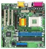
ASRock K7VM2 User Manual
ASRock K7VM2 Manual
 |
View all ASRock K7VM2 manuals
Add to My Manuals
Save this manual to your list of manuals |
ASRock K7VM2 manual content summary:
- ASRock K7VM2 | User Manual - Page 1
K7VM2 User Manual Version 1.0 Published October 2002 Copyright©2002 ASRock INC. All rights reserved. 1 - ASRock K7VM2 | User Manual - Page 2
owners' benefit, without intent to infringe. Disclaimer: Specifications and information contained in this manual are furnished for informational use only and subject to change without notice, and should not be constructed as a commitment by ASRock. ASRock assumes no responsibility for any errors or - ASRock K7VM2 | User Manual - Page 3
4 1.1 Package Contents 4 1.2 Specifications 4 1.3 Motherboard Layout 6 1.4 ASRock I/O 7 TM ...2 Installation 8 2.1 Screw Holes 8 2.2 Pre-installation Precautions 8 2.3 CPU Installation 8 2.4 Installation of Heatsink and CPU fan 9 2.5 Installation of Memory Modules (DIMM 9 2.6 Expansion - ASRock K7VM2 | User Manual - Page 4
x 9.6") ASRock K7VM2 Quick Installation Guide ASRock AMD-VIA Series Support CD 1 cable for IDE devices (1 x ATA 66/100/133) 1 cable for floppy drive (1 x ribbon cable) 1 ASRock I/O shield 1 COM port bracket 1.2 Specifications Platform: CPU: Chipsets: Clock Generator: Memory: IDE: Floppy Port: Audio - ASRock K7VM2 | User Manual - Page 5
(USB 2.0) 1 VGA port 1 Parallel port, supports ECP/EPP Audio Jack: Line Out/ Line In/ Microphone + Game port AMI legal BIOS Supports "Plug and Play" ACPI 1.1 compliance wake up events Supports jumperfree SMBIOS 3.0 support CPU frequency stepless control (only for advanced users' reference) Windows - ASRock K7VM2 | User Manual - Page 6
Motherboard Layout 1 27 2 3 45 6 24.4cm (9.6 in) PS/2 Mouse PS/2 Keyboard VGA SOCKET 462 BIOS AUDIO CODEC VIA Chipset Accelerated Graphics Port PCI 1 1 AUDIO1 K7VM2 power connector (ATXPWR1) 2 CPU socket 3 CPU fan connector (CPU_FAN1) 4 Memory 12 System panel connector (PANEL1) 13 USB - ASRock K7VM2 | User Manual - Page 7
1.4 ASRock I/OTM 1 2 3 10 9 1 Parallel port 2 RJ-45 port 3 Game port 4 Microphone (Pink) 5 Line In (Light Blue) 8 7 654 6 Line Out (Lime) 7 USB 2.0 ports 8 VGA port 9 PS/2 keyboard port (Purple) 10 PS/2 mouse port (Green) 7 - ASRock K7VM2 | User Manual - Page 8
supply. Failure to do so may cause severe damage to the motherboard, peripherals, and/ or components. 2.3 CPU Installation Step 1. Unlock the socket by lifting the lever up to a 90 to 100 angle. Step 2. Position the CPU directly above the socket such that its marked corner matches the base of the - ASRock K7VM2 | User Manual - Page 9
in good contact with each other. For proper installation, please kindly refer to the instruction manuals of vendors of CPU fan and heatsink. 2.5 Installation of Memory Modules (DIMM) SDRAM (Synchronous DRAM) DIMM (Dual In-line Memory Module) has 168 pins and DDR (Double Data Rate) SDRAM DIMM has 184 - ASRock K7VM2 | User Manual - Page 10
slots are used to install expansion cards that have the 32-bit PCI interface. AMR slot: AMR slot is used to insert ASRock AMR card with v.92 Modem functionality. On K7VM2 motherboard, the AMR slot shares the bracket with the slot PCI 3. AGP slot: The AGP slot is used to install a graphics card - ASRock K7VM2 | User Manual - Page 11
FSB_SEL1 2_3 FSB_SEL1 1_2 FSB 100 MHz FSB 133 MHz Note: Follow the figures to set the CPU front side bus frequency. PS2_USB_PWR1 (see p.6 item 22) 1_2 +5V 2_3 +5VSB Short pin2, pin3 to enable +5VSB (standby) for PS/2 or USB wake - ASRock K7VM2 | User Manual - Page 12
Secondary IDE connector (Black) (39-pin IDE2) (see p.6 item 8) PIN1 IDE1 PIN1 IDE2 Blue Connect to the motherboard Black Connect to the IDE devices 80-Pin ATA 100/133 cable Note: To optimize compatibility and performance, please connect your hard disk drive to the primary IDE connector (IDE1 - ASRock K7VM2 | User Manual - Page 13
(4-pin SPEAKER 1) (see p.6 item 15) Chassis fan connector (3-pin CHA_FAN1) (see p.6 item 9) CPU fan connector (3-pin CPU_FAN1) (see p.6 item 3) ATX power connector (20-pin ATXPWR1) (see p.6 item #1 DDSR#1 CCTS#1 1 RRI#1 RRTS#1 GND TTXD1 DDCD#1 This connector supports a serial port module. 13 - ASRock K7VM2 | User Manual - Page 14
Setup Utility This section explains how to configure your system using the BIOS Setup utility. The Flash Memory on the motherboard stores the BIOS Setup utility. When you start up the computer, there is a chance for you to run the BIOS Setup. Press during the Power-On-Self-Test (POST) to enter - ASRock K7VM2 | User Manual - Page 15
Saves changes and exits Setup 3.2 Main Menu When you enter the BIOS Setup utility, the following screen appears. System Date [Month/Day/Year move between the Month, Day and Year fields. System Time [Hour:Minute:Second] Set the system to the time that you specify. Use keys to move between the - ASRock K7VM2 | User Manual - Page 16
may due to that the hard disk is too old or too new. If the hard disk was already formatted on an older system, the BIOS Setup may detect incorrect parameters. In these cases, select [User] to manually enter the IDE hard disk drive parameters. After entering the hard disk information into - ASRock K7VM2 | User Manual - Page 17
BIOS based on the drive information you entered. LBA Mode This allows user to select the LBA mode for a hard disk > 512 MB under DOS and Windows; for Netware and UNIX user, Advanced, Security, Power, Boot, and Exit Menus Detailed descriptions of these menus are listed in the Appendix, see p.19. 17 - ASRock K7VM2 | User Manual - Page 18
detects installed devices. Install the necessary drivers to activate the devices. 4.2.3 Utilities Menu The Utilities Menu shows the applications software that the motherboard supports. Click on a specific item then follow the installation wizard to install it. 4.2.4 ASRock PC-DIY Live Demo Program - ASRock K7VM2 | User Manual - Page 19
: [Auto]: The motherboard detects the memory module(s) inserted and automatically assigns appropriate frequency. [Other values]: This allows user to select the value as operating frequency. Chipset Configuration: AGP Mode: This motherboard supports the AGP 4X interface that transfers video data at - ASRock K7VM2 | User Manual - Page 20
. USB Device Legacy Support: Use this to enable or disable support to emulate legacy I/O devices such as mouse, keyboard,... etc. Resource Configuration: PCI Latency Timer (PCI Clocks): The default is 32. We recommend you to keep the default value unless your PCI expansion cards' specifications - ASRock K7VM2 | User Manual - Page 21
onboard AC'97 audio feature. OnBoard MC'97 Modem: Enable or disable onboard MC'97 modem feature. 2. Security Setup Menu Supervisor Password: This field shows the status of the Supervisor Password. [Clear]: No password has been set. [Set]: Supervisor password has been set. User Password: This field - ASRock K7VM2 | User Manual - Page 22
] will enable this feature if the system supports it. Repost Video on S3 Resume: This feature allows you to repost video on S3 resume. Restore on AC/Power -off mode. RTC Alarm Power On: Use this to enable or disable RTC(Real Time Clock) to power on the system. If [Enable] is selected, you must fill - ASRock K7VM2 | User Manual - Page 23
Mode: This mode speeds up the boot-up routine by skipping memory retestings. Boot-time Diagnostic Screen: This screen shows CPU and hardware information during Power-On-Self-Test (POST) routine. If this screen is disabled, only ASRock logo is shown during the boot up process. Boot Up Num-Lock: This - ASRock K7VM2 | User Manual - Page 24
the sub-menu, the message "Save current settings and exit" will appear. If you press , it will save the current settings and exit the BIOS SETUP Utility. Exit Discarding Changes: After you enter the submenu, the message "Quit without saving changes" will appear. If you press , you will
-
 1
1 -
 2
2 -
 3
3 -
 4
4 -
 5
5 -
 6
6 -
 7
7 -
8
-
9
-
10
-
11
-
12
-
13
-
14
-
15
-
16
-
17
-
18
-
19
-
20
-
21
-
22
-
23
-
24
 |
 |

1
K7VM2
User Manual
Version 1.0
Published October 2002
Copyright©2002 ASRock INC. All rights reserved.