ASRock K7VM4 User Manual
ASRock K7VM4 Manual
 |
View all ASRock K7VM4 manuals
Add to My Manuals
Save this manual to your list of manuals |
ASRock K7VM4 manual content summary:
- ASRock K7VM4 | User Manual - Page 1
K7VM4 User Manual Version 1.1 Published July 2003 Copyright©2003 ASRock INC. All rights reserved. 1 - ASRock K7VM4 | User Manual - Page 2
any form or by any means, except duplication of documentation by the purchaser for backup purpose, without written consent of ASRock Inc. Products and corporate names appearing in this manual may or may not be registered trademarks or copyrights of their respective companies, and are used only for - ASRock K7VM4 | User Manual - Page 3
Package Contents 4 1.2 Specifications 5 1.3 Motherboard Layout 7 1.4 ASRock I/OTM 8 2 Installation 9 2.1 Screw Holes 9 2.2 Pre-installation Precautions 9 2.3 CPU Installation 10 2.4 Installation of Heatsink and CPU fan 10 2.5 Installation of Memory Modules (DIMM 11 2.6 Expansion Slots 11 - ASRock K7VM4 | User Manual - Page 4
any modifications of this manual occur, the updated version will be available on ASRock website without further notice. You may find the latest memory and CPU support lists on ASRock website as well. ASRock website http://www.asrock.com 1.1 Package Contents ASRock K7VM4 motherboard (Micro ATX form - ASRock K7VM4 | User Manual - Page 5
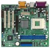
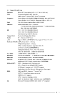
24.4 x 21.8 cm) CPU: Supports Socket A (462 pins) for AMD AthlonTM / AthlonTM XP/ DuronTM processor Chipsets: North Bridge: VIA KM400, FSB@333/266/200 MHz, AGP 8X/4X South Bridge: VIA VT8235CE, supports USB 2.0, ATA 133 VGA: VIA UniChrome Graphics, Max. 64MB VRAM Memory: 2 DDR DIMM slots - ASRock K7VM4 | User Manual - Page 6
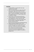
to spray thermal grease between the CPU and the heatsink when you install the PC system. 3. Do NOT insert a 3.3V AGP card into the AGP slot of K7VM4 motherboard! It may cause permanent damage! 4. Power Management for USB 2.0 works fine under Microsoft® Windows® XP. It may not work properly under - ASRock K7VM4 | User Manual - Page 7
in) VGA 30 29 28 27 26 25 24 23 22 LAN USB 2.0 Ports USB 2.0 Ports GGAAMMEE AAUUDDIIOO11 ATXPWR1 Line out LiLInnineein MMIniicc in LAN PHY 1 PS2_USB_PWR1 CPU_FAN1 2MB BIOS VIA KM400 K7VM4 Chipset AGP1 01 23 IDE2 IDE1 CMOS Battery AUDIO CODEC AUDIO1 1 JR1 JL1 Super I/O AMR1 PCI 1 AGP 8X - ASRock K7VM4 | User Manual - Page 8
1.4 ASRock I/OTM 1 2 3 10 9 8 7 654 1 Parallel port 3 Game port 5 Line In (Light Blue) 7 USB 2.0 ports 9 PS/2 keyboard port (Purple) 2 RJ-45 port 4 Microphone (Pink) 6 Line Out (Lime) 8 VGA port 10 PS/2 mouse port (Green) 8 - ASRock K7VM4 | User Manual - Page 9
Installation K7VM4 is a Micro ATX form factor (9.6" x 8.6", 24.4 x 21.8 cm) motherboard. Before you install the motherboard, study the configuration of your chassis to ensure that the motherboard fits into it. Make sure to unplug the power cord before installing or removing the motherboard. Failure - ASRock K7VM4 | User Manual - Page 10
Thermal grease between the CPU and the heatsink is also needed to improve heat transfer. Make sure that the CPU and the heatsink are securely fastened and in good contact with each other. For proper installation, please kindly refer to the instruction manuals of vendors of CPU fan and heatsink. 10 - ASRock K7VM4 | User Manual - Page 11
of Memory Modules (DIMM) K7VM4 motherboard provides two AGP slot: The AGP slot is used to install a graphics card. The ASRock AGP slot has a special locking mechanism which can securely fasten the graphics card inserted. Do NOT insert a 3.3V AGP card into the AGP slot of K7VM4 motherboard - ASRock K7VM4 | User Manual - Page 12
motherboard is by means of the adjustment of jumper-setting. Please follow the figures above to set the CPU front side bus frequency. PS2_USB_PWR1 1_2 2_3 Short pin2, pin3 to enable (see p.7 item 29) +5V +5VSB +5VSB (standby) for PS/2 or USB audio connectors can work. 2. If both jumper caps on - ASRock K7VM4 | User Manual - Page 13
For example, "Athlon XP 2000+" is an 1666MHz CPU: 12.5 (Multiplier) X 133MHz (External frequency) = 1666MHz FID jumpers setting: FID0 FID1 FID2 FID3 FID4 11111 The jumper caps are not provided by ASRock. Please understand that ASRock does not guarantee and support the adjustment of multiplier - ASRock K7VM4 | User Manual - Page 14
CLRCMOS1 (see p.7 item 10) Clear CMOS 2-pin jumper Note: CLRCMOS1 allows you to clear the data in CMOS. The data in CMOS includes system setup information such as system password, date, time, and system setup parameters. To clear and reset the system parameters to default setup, please turn off - ASRock K7VM4 | User Manual - Page 15
IRTX +5V DUMMY 1 GND IRRX AUX-R GND GND AUX-L AUX1 CD-R GND GND CD-L CD1 This connector supports an optional wireless transmitting and receiving infrared module. These connectors allow you to receive stereo audio input from sound sources such as a CD-ROM, DVD-ROM, TV tuner card, or MPEG card. 15 - ASRock K7VM4 | User Manual - Page 16
audio devices. This connector accommodates several system front panel functions. This connector allows you to attach to an external speaker. CHA_FAN_SPEED +12V GND Connect the fan cable to the connector matching the black wire to the ground pin. CPU COM1 header supports a serial port module. 16 - ASRock K7VM4 | User Manual - Page 17
use the BIOS Setup Utility to configure your system. The Flash Memory on the motherboard stores the BIOS Setup Utility. You may run the BIOS Setup Utility among the predetermined choices. Because the BIOS software is constantly being updated, the following BIOS setup screens and descriptions are for - ASRock K7VM4 | User Manual - Page 18
2003 Wed 20:07:40 [ Setup Help ] Month: Jan - Dec Day: 01 - 31 Year: 1980 - 2099 K7VM4 BIOS P1.00 AMD Athlon(tm) XP 2600+ 2133 MHz 128 KB 256 KB 480 MB + 32 MB Share Memory 512 MB / 133 MHz (DDR 266) None F1:Help Esc:Exit :Select Item :Select Menu +/-:Change Values - ASRock K7VM4 | User Manual - Page 19
may due to that the hard disk is too old or too new. If the hard disk was already formatted on an older system, the BIOS Setup may detect incorrect parameters. In these cases, select [User] to manually enter the IDE hard disk drive parameters. After entering the hard disk information into - ASRock K7VM4 | User Manual - Page 20
per track. Refer to the drive documentation to determine the correct value. Maximum Capacity This field shows the drive's maximum capacity as calculated by the BIOS based on the drive information you entered. LBA Mode This allows user to select the LBA mode for a hard disk > 512 MB under DOS and - ASRock K7VM4 | User Manual - Page 21
installed devices. Please install the necessary drivers to activate the devices. 4.2.3 Utilities Menu The Utilities Menu shows the applications software that the motherboard supports. Click on a specific item then follow the installation wizard to install it. 4.2.4 ASRock PC-DIY Live Demo Program - ASRock K7VM4 | User Manual - Page 22
user to set the CPU host frequency manually. However, this is not recommended unless user thoroughly knows the feature. Wrong setup may cause problems during operation. DRAM Frequency: If set to [Auto], the motherboard will detect the inserted memory module(s) and automatically assign appropriate - ASRock K7VM4 | User Manual - Page 23
: When an 8X-AGP card is installed on K7VM4 motherboard for your PC system, this feature will be set to [Auto] automatically. If the installed AGP card is not an 8X-AGP card, then it will be set to [4X] as the default value. AGP Aperture Size: It refers to a section of the PCI memory address range - ASRock K7VM4 | User Manual - Page 24
other settings. Primary Graphics Adapter: Select PCI or AGP as the primary graphics adapter. Peripheral Configuration: Advanced Midi Port Midi IRQ Select OnBoard Game Port OnBoard IDE OnBoard LAN OnBoard AC' 97 Audio OnBoard MC' 97 Modem Auto Auto Disabled Auto ECP+EPP 1.9 Auto Auto Disabled 5 - ASRock K7VM4 | User Manual - Page 25
onboard AC'97 Audio feature. OnBoard MC'97 Modem: Select [Auto] or [Disabled] for the onboard MC'97 Modem feature. System Hardware Monitor: You can check the status of the hardware on your system. It allows you to monitor the parameters for CPU temperature, Motherboard temperature, CPU fan speed - ASRock K7VM4 | User Manual - Page 26
p assword. Password Check: Select the check point for "Password Check". Configuration options: [Setup], [Always]. If [Setup] option is selected, the "Password Check" is performed before BIOS setup. If [Always] option is selected, the "Password Check" is performed before both boot-up and - ASRock K7VM4 | User Manual - Page 27
allows you to select whether to auto-detect or disable the Suspend-to-RAM feature. Select [Auto] will enable this feature if the system supports it. Repost Video on STR Resume: This feature allows you to repost video on STR resume. It is recommended to enable this feature under Microsoft® Windows - ASRock K7VM4 | User Manual - Page 28
Enter:Select Sub-Menu F9:Setup Defaults F10:Save & Exit Quick Boot Mode: Enable this mode will speed up the boot-up routine by skipping memory retestings. Boot Up Num-Lock: If this is enabled, it will automatically activate the Numeric Lock function after boot-up. Boot To OS/2: Select [Yes - ASRock K7VM4 | User Manual - Page 29
[ Enter ] [ Setup Help ] Exits and saves the changes to CMOS RAM. F1:Help Esc:Exit :Select Item :Select Menu +/-:Change Values Enter:Select If you press , it will save the current settings and exit the BIOS SETUP Utility. Exit Discarding Changes: After you enter the submenu, the message "
-
 1
1 -
 2
2 -
 3
3 -
 4
4 -
 5
5 -
 6
6 -
 7
7 -
8
-
9
-
10
-
11
-
12
-
13
-
14
-
15
-
16
-
17
-
18
-
19
-
20
-
21
-
22
-
23
-
24
-
25
-
26
-
27
-
28
-
29
 |
 |

1
K7VM4
User Manual
Version 1.1
Published July 2003
Copyright©2003 ASRock INC. All rights reserved.