ASRock K7VT2 User Manual
ASRock K7VT2 Manual
 |
View all ASRock K7VT2 manuals
Add to My Manuals
Save this manual to your list of manuals |
ASRock K7VT2 manual content summary:
- ASRock K7VT2 | User Manual - Page 1
K7VT2 User Manual Version 1.1 Published November 2002 Copyright©2002 ASRock INC. All rights reserved. 1 - ASRock K7VT2 | User Manual - Page 2
backup purpose, without written consent of ASRock Inc. Products and corporate names appearing in this manual may or may not be registered trademarks benefit, without intent to infringe. Disclaimer: Specifications and information contained in this manual are furnished for informational use only and - ASRock K7VT2 | User Manual - Page 3
4 1.1 Package Contents 4 1.2 Specifications 4 1.3 Motherboard Layout 6 1.4 ASRock I/O 7 TM ...2 Installation 8 2.1 Screw Holes 8 2.2 Pre-installation Precautions 8 2.3 CPU Installation 8 2.4 Installation of Heatsink and CPU fan 9 2.5 Installation of Memory Modules (DIMM 9 2.6 Expansion - ASRock K7VT2 | User Manual - Page 4
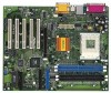
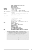
Contents ASRock K7VT2 motherboard (ATX form factor: 12" x 9.6", 30.5 x 24.4 cm) ASRock K7VT2 Quick Installation Guide ASRock AMD-VIA Series Support CD 1 cable for IDE devices (1 x ATA 66/100/133) 1 cable for floppy drive (1 x ribbon cable) 1 ASRock I/O shield 1.2 Specifications Platform: CPU - ASRock K7VT2 | User Manual - Page 5
monitoring: +12V, +5V, +3V, Vcore; CPU fan tachometer; Chassis fan tachometer PCI slots: 5 slots with PCI Specification 2.2 AGP slot: 1 universal AGP slot, supports 3.3v / 1.5v, 4X / 2X / 1X AGP cards AMR slot (optional): 1 slot, supports ASRock MR card, shares the bracket with the slot PCI - ASRock K7VT2 | User Manual - Page 6
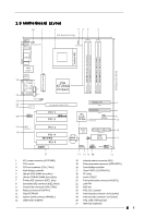
CLRCMOS1 CHA_FAN1 17 19 Audio CODEC 18 PCI 3 PCI 4 K7VT2 PCI 5 AMR1 Super 10 I/O FLOPPY1 CMOS IR1 2MB BIOS 11 Battery Speaker1 USB45 HDLED PWRBTN PANEL1 PLED RST 27 16 15 14 13 12 1 ATX power connector (ATXPWR1) 2 CPU socket 3 CPU fan connector (CPU_FAN1) 4 North - ASRock K7VT2 | User Manual - Page 7
1.4 ASRock I/OTM 1 2 3 10 9 8 7 654 1 Parallel port 2 RJ-45 port 3 Game port 4 Microphone (Pink) 5 Line In (Light Blue) 6 Line Out (Lime) 7 USB 2.0 ports 8 Serial port (COM1) 9 PS/2 keyboard port (Purple) 10 PS/2 mouse port (Green) 7 - ASRock K7VT2 | User Manual - Page 8
the power supply. Failure to do so may cause severe damage to the motherboard, peripherals, and/or components. 2.3 CPU Installation Step 1. Unlock the socket by lifting the lever up to a 900 angle. Step 2. Position the CPU directly above the socket such that its marked corner matches the base of the - ASRock K7VT2 | User Manual - Page 9
to the instruction manuals of vendors of CPU fan and heatsink. 2.5 Installation of Memory Modules (DIMM) SDRAM (Synchronous DRAM) DIMM (Dual In-line Memory Module)has and 184-pin DDR DIMM at the same time. Only use one single type of DIMMs at one time. Also, for proper operation, it is not - ASRock K7VT2 | User Manual - Page 10
slot: The AGP slot is used to install a graphics card. The ASRock AGP slot has a special locking mechanism which can securely fasten the graphics card inserted. AMR slot (optional): The AMR slot on K7VT2 motherboard is only for the use of ASRock MR card with v.92 Modem functionality. (The AMR slot - ASRock K7VT2 | User Manual - Page 11
and pin2 are "SHORT". Jumper Setting Description FSB_SEL1 (see p.6 item 23) FSB_SEL1 2_3 FSB_SEL1 1_2 FSB 100 MHz FSB 133 MHz Note: Follow the figures to set the CPU front side bus frequency. PS2_USB_PWR1 1_2 2_3 Short pin2, pin3 to enable (see p.6 item 26) +5VSB (standby) for PS - ASRock K7VT2 | User Manual - Page 12
motherboard BLACK Connect to the IDE devices 80-Pin ATA 100/133 cable Note: To optimize compatibility and audio input from sound sources such as a CD-ROM, DVD-ROM, TV tuner card, or MPEG card. This is an interface for front panel audio cable that allows convenient connection and control of audio - ASRock K7VT2 | User Manual - Page 13
Chassis fan connector (3-pin CHA_FAN1) (see p.6 item 9) CPU fan connector (3-pin CPU_FAN1) (see p.6 item 3) ATX power connector (20-pin ATXPWR1) (see p.6 item 1) GND +12V CHA_FAN_SPEED Connect the fan cable to the connector matching - ASRock K7VT2 | User Manual - Page 14
BIOS Setup Utility. The Flash Memory on the motherboard stores the BIOS Setup Utility. When you start up the computer, there is a chance for you to run the BIOS then back on. The BIOS Setup Utility is designed to BIOS software is constantly being updated, the following BIOS menu or the BIOS Setup To - ASRock K7VT2 | User Manual - Page 15
Processor Type Processor Speed L1 Cache Size L2 Cache Size Total Memory DDR1 DDR2 SDR1 SDR2 AMIBIOS SETUP UTILITY - VERSION 3.31a Security Power Boot Exit Nov 06 2002 Wed 19:07:40 [ Setup Help ] Month: Jan - Dec Day: 01 - 31 Year: 1980 - 2099 K7VT2 BIOS P1.00 AMD Duron(tm) Processor 800MHz - ASRock K7VT2 | User Manual - Page 16
may due to that the hard disk is too old or too new. If the hard disk was already formatted on an older system, the BIOS Setup may detect incorrect parameters. In these cases, select [User] to manually enter the IDE hard disk drive parameters. After entering the hard disk information into - ASRock K7VT2 | User Manual - Page 17
shows the drive's maximum capacity as calculated by the BIOS based on the drive information you entered. LBA Mode for a hard disk > 512 MB under DOS and Windows; for Netware and UNIX user, select [Off] to improves transfer speeds and data integrity for compatible IDE devices. Set to [Disabled] to - ASRock K7VT2 | User Manual - Page 18
detects installed devices. Install the necessary drivers to activate the devices. 4.2.3 Utilities Menu The Utilities Menu shows the applications software that the motherboard supports. Click on a specific item then follow the installation wizard to install it. 4.2.4 ASRock PC-DIY Live Demo Program - ASRock K7VT2 | User Manual - Page 19
This allows the user to set CPU host frequency manually. However, this is not recommended unless you thoroughly knows the feature. Wrong setup may cause problems during operation. SDRAM Frequency: If [Auto] is selected, the motherboard detects the memory module(s) inserted and automatically assigns - ASRock K7VT2 | User Manual - Page 20
or disable support to emulate legacy I/O devices such as mouse, keyboard,... etc. Resource Configuration: PCI Latency Timer (PCI Clocks): The default is 32. We recommend you to keep the default value unless your PCI expansion cards' specifications require other settings. Primary Graphics Adapter - ASRock K7VT2 | User Manual - Page 21
audio feature. OnBoard MC'97 Modem: Allows you to set [Auto] or [Disabled] for onboard MC'97 modem feature. System Hardware Monitor: You can check the status of the hardware on your system. It allows you to monitor the parameters for CPU temperature, Motherboard temperature, CPU BIOS setup. If - ASRock K7VT2 | User Manual - Page 22
allows you to select whether to auto-detect or disable the ACPI Suspend-to-RAM feature. Select [Auto] will enable this feature if the system supports it. Repost Video on S3 Resume: This feature allows you to repost video on S3 resume. Restore on AC/Power Loss: This allows you to - ASRock K7VT2 | User Manual - Page 23
Boot Mode: This mode speeds up the boot-up routine by skipping memory retestings. Boot-time Diagnostic Screen: This screen shows CPU and hardware information during Power-On-Self-Test (POST) routine. If this screen is disabled, only ASRock logo is shown during the boot up process. Boot Up Num-Lock - ASRock K7VT2 | User Manual - Page 24
the sub-menu, the message "Save current settings and exit" will appear. If you press , it will save the current settings and exit the BIOS SETUP Utility. Exit Discarding Changes: After you enter the submenu, the message "Quit without saving changes" will appear. If you press , you will
-
 1
1 -
 2
2 -
 3
3 -
 4
4 -
 5
5 -
 6
6 -
 7
7 -
8
-
9
-
10
-
11
-
12
-
13
-
14
-
15
-
16
-
17
-
18
-
19
-
20
-
21
-
22
-
23
-
24
 |
 |
1
K7VT2
User Manual
Version 1.1
Published November 2002
Copyright©2002 ASRock INC. All rights reserved.