ASRock K7VT4A User Manual
ASRock K7VT4A Manual
 |
View all ASRock K7VT4A manuals
Add to My Manuals
Save this manual to your list of manuals |
ASRock K7VT4A manual content summary:
- ASRock K7VT4A | User Manual - Page 1
K7VT4A+ User Manual Version 1.0 Published May 2004 Copyright©2004 ASRock INC. All rights reserved. 1 - ASRock K7VT4A | User Manual - Page 2
backup purpose, without written consent of ASRock Inc. Products and corporate names appearing in this manual may or may not be registered trademarks benefit, without intent to infringe. Disclaimer: Specifications and information contained in this manual are furnished for informational use only and - ASRock K7VT4A | User Manual - Page 3
1. Introduction 4 1.1 Package Contents 4 1.2 Specifications 5 1.3 Motherboard Layout 7 1.4 ASRock I/O 8 TM ...2. Installation 9 Pre-installation Precautions 9 2.1 CPU Installation 10 2.2 Installation of CPU Fan and Heatsink 10 2.3 Installation of Memory Modules (DIMM 11 2.4 Expansion Slots - ASRock K7VT4A | User Manual - Page 4
find the latest memory and CPU support lists on ASRock website as well. ASRock website http://www.asrock.com 1.1 Package Contents 1 x ASRock K7VT4A+ Motherboard (ATX Form Factor: 12.0-in x 7.0-in, 30.5 cm x 17.8 cm) 1 x ASRock K7VT4A+ Quick Installation Guide 1 x ASRock K7VT4A+ Support CD 1 x Ultra - ASRock K7VT4A | User Manual - Page 5
1.2 Specifications Platform: ATX Form Factor: 12.0-in x 7.0-in, 30.5 cm x 17.8 cm CPU: Supports Socket A (462 pins) for AMD AthlonTM / AthlonTM XP / DuronTM processor Chipsets: North Bridge: VIA KT400A, FSB@333 MHz South Bridge: VIA VT8235CD, supports USB 2.0, ATA 133 Memory: 2 DDR DIMM - ASRock K7VT4A | User Manual - Page 6
the recommended CPU bus frequencies may cause the instability of the system or damage the CPU. The CPU host frequency of this motherboard is determined by the jumper-setting. You must set the FSB jumper according to your AMD CPU before you use the "Manual" option as the FSB setting in BIOS setup - ASRock K7VT4A | User Manual - Page 7
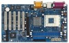
LIINnE IN KT400A AUX1 CHIPSET MMInICicIN 7 24 CD1 8 JR1 23 JL1 1 AUDIO1 AGP 8X K7VT4A+ 22 1.5V_AGP1 9 AUDIO CODEC LAN PHY SUPER I/O DDR400 PCI1 PCI2 1 FSB_SEL0 1 FSB_SEL1 1 FSB_SEL2 10 21 20 2MB BIOS PCI3 USB2.0 5.1CH PCI4 11 VIA VT8235 12 CHA_FAN1 CMOS ATA133 - ASRock K7VT4A | User Manual - Page 8
1.4 ASRock I/OTM 1 2 3 10 9 8 1 Parallel Port 2 RJ-45 Port 3 Game Port 4 Microphone (Pink) 5 Line In (Light Blue) 7 654 6 Line Out (Lime) 7 USB 2.0 Ports 8 Serial Port (COM1) 9 PS/2 Keyboard Port (Purple) 10 PS/2 Mouse Port (Green) 8 - ASRock K7VT4A | User Manual - Page 9
you install or remove any component, ensure that the power is switched off or the power cord is detached from the power supply. Failure to do so may cause severe damage to the motherboard, peripherals, and/or components. 1. Unplug the power cord from the wall socket before touching any component - ASRock K7VT4A | User Manual - Page 10
. Make sure that the CPU and the heatsink are securely fastened and in good contact with each other. Then connect the CPU fan to the CPU_FAN connector (CPU_FAN1, see page 7, No. 2). For proper installation, please kindly refer to the instruction manuals of the CPU fan and heatsink vendors. 10 - ASRock K7VT4A | User Manual - Page 11
2.3 Installation of Memory Modules (DIMM) K7VT4A+ motherboard provides two 184-pin DDR (Double Data Rate) DIMM slots. Please make sure to disconnect power supply before adding or removing DIMMs or the system components. Step 1. Step 2. Unlock a DIMM slot by pressing the retaining clips outward. - ASRock K7VT4A | User Manual - Page 12
make sure that the power supply is switched off or the power cord is unplugged. Please read the documentation of the expansion card and make necessary hardware settings for the card before you start the installation. Step 2. Remove the system unit cover (if your motherboard is already installed in - ASRock K7VT4A | User Manual - Page 13
and unplug the power cord from the power supply. After waiting for 15 seconds, use a jumper cap to short the Clear CMOS jumper for 5 seconds. After shorting the Clear CMOS jumper, please remove the jumper cap. However, please do not clear the CMOS right after you update the BIOS. If you need - ASRock K7VT4A | User Manual - Page 14
The jumper caps are not provided by ASRock. Please understand that ASRock does not guarantee and support the adjustment of multiplier. These jumpers setting may not apply to all multiplier-locked or even some unlocked AMD CPU. Frequencies other than the recommended CPU bus frequencies may cause the - ASRock K7VT4A | User Manual - Page 15
motherboard, please set the IDE device as "Master". Please refer to the instruction GND DUMMY 1 GND P+4 P-4 USB_PWR ASRock I/OTM provides you 4 default USB support 2 additional USB 2.0 ports. Infrared Module Connector (5-pin IR1) (see p.7 item 18) IRTX +5V DUMMY 1 GND IRRX This connector supports - ASRock K7VT4A | User Manual - Page 16
(see p.7 item 2) CPU_FAN_SPEED +12V GND Please connect a CPU fan cable to this connector and match the black wire to the ground pin. ATX Power Connector (20-pin ATXPWR1) (see p.7 item 6) Please connect an ATX power supply to this connector. Power LED Connector (3-pin PWR_LED1) (see p.7 item 14 - ASRock K7VT4A | User Manual - Page 17
Memory on the motherboard stores the BIOS Setup Utility. You may run the BIOS Setup when you start up the computer. Please press during the PowerOn-Self-Test (POST) to enter the BIOS choices. Because the BIOS software is constantly being updated, the following BIOS setup screens and descriptions - ASRock K7VT4A | User Manual - Page 18
Processor Speed L1 Cache Size L2 Cache Size Total Memory DDR1 DDR2 AMIBIOS SETUP UTILITY - VERSION 3.31a Security Power Boot Exit Oct 31 2003 Fri 20:07:40 [ Setup Help ] Month: Jan - Dec Day: 01 - 31 Year: 1980 - 2099 K7VT4A+ BIOS P1.00 AMD Athlon(tm) XP 2600+ 2133 MHz 128 KB 256 KB 512 - ASRock K7VT4A | User Manual - Page 19
hard disk drive, make sure you have the correct configuration information supplied by the drive manufacturer. Incorrect settings may cause the system formatted on an older system, the BIOS Setup may detect incorrect parameters. In these cases, select [User] to manually enter the IDE hard disk drive - ASRock K7VT4A | User Manual - Page 20
shows the drive's maximum capacity as calculated by the BIOS based on the drive information you entered. LBA Mode for a hard disk > 512 MB under DOS and Windows; for Netware and UNIX user, select [Off] to disable DMA capability. 3.3 Advanced, Security, Power, Boot, and Exit Menus Detailed descriptions of - ASRock K7VT4A | User Manual - Page 21
detects installed devices. Install the necessary drivers to activate the devices. 4.2.3 Utilities Menu The Utilities Menu shows the applications software that the motherboard supports. Click on a specific item then follow the installation wizard to install it. 4.2.4 ASRock PC-DIY Live Demo Program - ASRock K7VT4A | User Manual - Page 22
according to your AMD CPU before you use this "Manual" option as the FSB setting in BIOS setup to perform over clocking. This is not recommended unless you thoroughly know the feature. Wrong setup may cause problems during operation. DRAM Frequency If set to [Auto], the motherboard will detect the - ASRock K7VT4A | User Manual - Page 23
address range used for graphics memory. It is recommended to leave this field at the default value unless the installed AGP card's specifications requires other sizes. AGP Fast Write This allows you to enable or disable the feature of AGP fast write protocol support. PCI Delay Transaction Enable PCI - ASRock K7VT4A | User Manual - Page 24
is [Disabled]. It is not recommended to enable "Over Vcore Voltage" feature. Doing so may cause CPU damage. V-Link Speed This feature default is 32. It is recommended to keep the default value unless the installed PCI expansion cards' specifications require other settings. Primary Graphics Adapter - ASRock K7VT4A | User Manual - Page 25
Version Parallel Port IRQ Parallel Port DMA Channel OnBoard Midi Port Midi IRQ Select OnBoard Game Port OnBoard IDE OnBoard LAN OnBoard AC' 97 Audio Auto Auto Disabled Auto ECP+EPP 1.9 Auto Auto Disabled 5 200h Both Enabled Auto to enable or disable the floppy drive controller. F1:Help - ASRock K7VT4A | User Manual - Page 26
], [Auto] or [Enabled] for the onboard AC'97 Audio feature. System Hardware Monitor You may check the status of the hardware on your system. It allows you to monitor the parameters for CPU temperature, Motherboard temperature, CPU fan speed, and critical voltage. Advanced AMIBIOS SETUP UTILITY - ASRock K7VT4A | User Manual - Page 27
Menu Main Advanced AMIBIOS SETUP UTILITY - VERSION 3.31a Security Power Boot Exit Supervisor Password User Password Set Supervisor Password Set User [Setup] option is selected, the "Password Check" is performed before BIOS setup. If [Always] option is selected, the "Password Check" is performed before - ASRock K7VT4A | User Manual - Page 28
or disable the Suspendto-RAM feature. Select [Auto] will enable this feature if the system supports it. Repost Video on STR Resume This feature allows you to repost video on STR resume. It is recommended to enable this feature under Microsoft® Windows® 98 / ME. Restore on AC/Power Loss This allows - ASRock K7VT4A | User Manual - Page 29
Menu Main Advanced AMIBIOS SETUP UTILITY - VERSION 3.31a Security Power Boot Exit Quick Boot Mode Boot Up Num-Lock Boot Exit Quick Boot Mode Enable this mode will speed up the boot-up routine by skipping memory retestings. Boot Up Num-Lock If this is enabled, it will automatically activate the - ASRock K7VT4A | User Manual - Page 30
Power Boot Exit Exit Saving Changes Exit Discarding Changes Load Default Settings Discard Changes [ Enter ] [ Enter ] [ Enter ] [ Enter ] [ Setup Help ] Exits and saves the changes in CMOS RAM will save the current settings and exit the BIOS SETUP Utility. Exit Discarding Changes After you enter
-
 1
1 -
 2
2 -
 3
3 -
 4
4 -
 5
5 -
 6
6 -
 7
7 -
8
-
9
-
10
-
11
-
12
-
13
-
14
-
15
-
16
-
17
-
18
-
19
-
20
-
21
-
22
-
23
-
24
-
25
-
26
-
27
-
28
-
29
-
30
 |
 |

1
K7VT4A+
User Manual
Version 1.0
Published May 2004
Copyright©2004 ASRock INC. All rights reserved.