ASRock K8 Combo-Z User Manual
ASRock K8 Combo-Z Manual
 |
View all ASRock K8 Combo-Z manuals
Add to My Manuals
Save this manual to your list of manuals |
ASRock K8 Combo-Z manual content summary:
- ASRock K8 Combo-Z | User Manual - Page 1
MOTHERBOARD K8 Combo-Z User Manual Version 1.0 Published July 2004 Copyright©2004 ASRock INC. All rights reserved. 1 - ASRock K8 Combo-Z | User Manual - Page 2
any form or by any means, except duplication of documentation by the purchaser for backup purpose, without written consent of ASRock Inc. Products and corporate names appearing in this manual may or may not be registered trademarks or copyrights of their respective companies, and are used only for - ASRock K8 Combo-Z | User Manual - Page 3
Connectors 18 2.8 Serial ATA (SATA) Hard Disks Installation 21 2.9 Making An SATA Driver Diskette 21 3. BIOS SETUP UTILITY 22 3.1 Introduction 22 3.1.1 BIOS Menu Bar 22 3.1.2 Navigation Keys 23 3.2 Main Screen 23 3.3 Advanced Screen 24 3.3.1 CPU Configuration 24 3.3.2 Chipset Configuration - ASRock K8 Combo-Z | User Manual - Page 4
4. Software Support 38 4.1 Install Operating System 38 4.2 Support CD Information 38 4.2.1 Running Support CD 38 4.2.2 Drivers Menu 38 4.2.3 Utilities Menu 38 APPENDIX: AMD's Cool 'n' QuietTM Technology ...... 39 4 - ASRock K8 Combo-Z | User Manual - Page 5
modifications of this manual occur, the updated version will be available on ASRock website without further notice. You may find the latest memory and CPU support lists on ASRock website as well. ASRock website http://www.asrock.com 1.1 Package Contents 1 x ASRock K8 Combo-Z Motherboard (ATX Form - ASRock K8 Combo-Z | User Manual - Page 6
.4 cm 1. 939-Pin Socket Supporting AMD AthlonTM 64FX Processor 2. 754-Pin Socket Supporting advanced 64-bit AMD AthlonTM 64 and 32-bit Sempron Processor (see CAUTION 1) Supports AMD's Cool 'n' QuietTM Technology (see CAUTION 2) Chipsets: Bridge: ALi M1689 Chipset 1. For 939-Pin CPU, FSB @ 1 GHz - ASRock K8 Combo-Z | User Manual - Page 7
/Bass / Line In / Front Speaker / Microphone (see CAUTION 8) AMI Legal BIOS Supports "Plug and Play" ACPI 1.1 Compliance Wake Up Events SMBIOS 2.3.1 Support CPU Frequency Stepless Control (only for advanced users' reference, see CAUTION 9) Microsoft® Windows® 98 SE / ME / 2000 / XP compliant 7 - ASRock K8 Combo-Z | User Manual - Page 8
memory modules on DDR1, DDR2, and DDR3. 4. If you install a 939-Pin CPU into this motherboard, it will support Dual Channel Memory Technology. Before you implement Dual Channel Memory Technology, make sure to read the installation guide of memory modules on page 14 for proper installation. 5. While - ASRock K8 Combo-Z | User Manual - Page 9
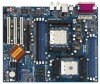
Jumper 2 ATX Power Connector (ATXPWR1) 3 CPU Heatsink Retention Module (for 939-Pin CPU) 4 939-Pin CPU Socket 5 184-pin DDR DIMM Slots (DDR4- 5, for 754-Pin CPU only) 6 CPU Heatsink Retention Module (for 754-Pin CPU) 7 754-Pin CPU Socket 8 J7 Jumper 9 CPU Fan Connector (CPU_FAN1) 10 J1 / J2 - ASRock K8 Combo-Z | User Manual - Page 10
1.4 ASRock 8CH I/O 1 13 12 11 2 3 6 4 7 5 8 10 9 1 Parallel Port 2 RJ-45 Port 3 Side Speaker ( COM1 12 PS/2 Keyboard Port (Purple) 13 PS/2 Mouse Port (Green) * If you use 2-channel speaker, please connect the speaker's plug into "Front Speaker Jack". See the table below for connection - ASRock K8 Combo-Z | User Manual - Page 11
2. Installation K8 Combo-Z is an ATX form factor (12.0-in x 9.6-in, 30.5 cm x 24.4 cm) motherboard. Before you install the motherboard, study the configuration of your chassis to ensure that the motherboard fits into it. Pre-installation Precautions Take note of the following precautions before you - ASRock K8 Combo-Z | User Manual - Page 12
of all these seven sets of jumpers. These jumpers are set to support 754-Pin CPU by shorting pin1 and pin2 by default. Please refer to the figure below for these jumpers' location on the motherboard. Socket 754 SOCKET 939 1 J5 1 J6 J5 / J6 Jumpers J7 1 J7 Jumper J1 1 1 1 1 1 1 1 1 1 1 J2 - ASRock K8 Combo-Z | User Manual - Page 13
Down And Lock To The Socket Corner The Socket Lever To avoid instability and damage to the system, please do not install both of 939-Pin CPU and 754-Pin CPU into this motherboard. 2.3 Installation of CPU Fan and Heatsink After you install the CPU into this motherboard, it is necessary to install - ASRock K8 Combo-Z | User Manual - Page 14
of Memory Modules (DIMM) This motherboard is equipped with five 184-pin DDR (Double Data Rate) DIMM slots. I. For 939-Pin CPU users, please install the DIMM into DDR1, DDR2 and DDR3 slots (see Page 9, No. 32). DDR1 and DDR2 slots support Dual Channel Memory Technology. Since there are some - ASRock K8 Combo-Z | User Manual - Page 15
matches the break on the slot. notch break notch break The DIMM only fits in one correct orientation. It will cause permanent damage to the motherboard and the DIMM if you force the DIMM into the slot at incorrect orientation. Step 3. Firmly insert the DIMM into the slot until the retaining - ASRock K8 Combo-Z | User Manual - Page 16
and AGP Slots) There are 3 PCI slots, and 1 AGP slot on K8 Combo-Z motherboard. PCI Slots: PCI slots are used to install expansion cards that have the 32-bit PCI interface. AGP slot: The AGP slot is used to install a graphics card. The ASRock AGP slot has a special design of clasp that can securely - ASRock K8 Combo-Z | User Manual - Page 17
2.6 Jumpers Setup The illustration shows how jumpers are setup. When the jumper cap is placed on pins, the jumper is "Short". If no jumper cap is placed on pins, the jumper is "Open". The illustration shows a 3-pin jumper whose pin1 and pin2 are "Short" when jumper cap is placed on these 2 pins. - ASRock K8 Combo-Z | User Manual - Page 18
ATA (SATA) connectors support SATA data cables for internal storage devices. The current SATA interface allows up to 1.5 Gb/s data transfer rate. Serial ATA (SATA) Data Cable Either end of the SATA data cable can be connected to the SATA hard disk or the SATA connector on the motherboard. 18 - ASRock K8 Combo-Z | User Manual - Page 19
connect the black end of SATA power cable to the power connector on each drive. Then connect the white end of SATA power cable to the power available to support 2 extra USB 2.0 ports. USB 2.0 Header (9-pin USB_H45) (see p.9, No. 20) USB_PWR P-5 P+5 GND DUMMY 1 GND P+4 P-4 USB_PWR ASRock 8CH I/OTM - ASRock K8 Combo-Z | User Manual - Page 20
Please connect the chassis fan cable to this connector and match the black wire to the ground pin. CPU Fan Connector (3-pin CPU_FAN1) (see p.9, No. 9) CPU_FAN_SPEED +12V GND Please connect the CPU fan cable to this connector and match the black wire to the ground pin. Game Connector (15-pin - ASRock K8 Combo-Z | User Manual - Page 21
other end of the SATA data cable to the SATA hard disk. 2.9 Making An SATA Driver Diskette If you want to install Windows 2000 or Windows XP on your SATA HDDs, you will need to make an SATA driver diskette before you start the OS installation. STEP 1: Insert the ASRock Support CD into your optical - ASRock K8 Combo-Z | User Manual - Page 22
the BIOS SETUP UTILITY to configure your system. The Flash Memory on the motherboard stores the BIOS SETUP UTILITY. You may run the BIOS SETUP off and then back on. Because the BIOS software is constantly being updated, the following BIOS setup screens and descriptions are for reference purpose - ASRock K8 Combo-Z | User Manual - Page 23
DDR 1 (K8_939) DDR 2 (K8_939) DDR 3 (K8_939) DDR 4 (K8_754) DDR 5 (K8_754) [17:00:09] [Fri 07/09/2004] : K8 Combo-Z BIOS P1.0 : AMD Athlon(tm) 64 Processor 3400+ : 2200 MHz : 128KB : 1024KB : 512MB Single-Channel Memory Mode : 512MB/133MHz (DDR266) : None : None : None : None Use [Enter], [TAB] or - ASRock K8 Combo-Z | User Manual - Page 24
Load Defaults Save and Exit Exit v02.54 (C) Copyright 1985-2003, American Megatrends, Inc. CPU Host Frequency While entering setup, BIOS auto detects the present CPU host frequency of this motherboard. The actual CPU host frequency will show in the following item. Spread Spectrum This item should - ASRock K8 Combo-Z | User Manual - Page 25
] by default. If it is set to [Manual], you may adjust the value of Processor Multiplier and Processor Voltage. However, it is recommended to keep the default value for system stability. BIOS SETUP UTILITY Advanced CPU Configuration CPU Host Frequency Actual Frequency (MHz) Spread Spectrum Cool - ASRock K8 Combo-Z | User Manual - Page 26
higher than [x11]. However, for system stability, it is not recommended to adjust the value of this item. Processor Voltage This item will show when "Multiplier/Voltage Change" is set to [Manual]; otherwise, it will be hidden. You may set the value from [1.550V] down to [0.800V]. However, for safety - ASRock K8 Combo-Z | User Manual - Page 27
BIOS item to enable or disable the feature of AGP fast write protocol support. Primary Graphics Adapter This item will switch the PCI Bus scanning controllers. HT Width For 939-Pin CPU, you may set the HyperTransport width as [8 BIT], [16 BIT], or [Auto]. For 754-Pin CPU, you may set the - ASRock K8 Combo-Z | User Manual - Page 28
3.3.3 ACPI Configuration Advanced BIOS SETUP UTILITY ACPI Settings Suspend To RAM Repost Video on to auto-detect or disable the Suspend-toRAM feature. Select [Auto] will enable this feature if the OS supports it. If you set this item to [Disabled], the function "Restore on AC/Power Loss" will be - ASRock K8 Combo-Z | User Manual - Page 29
We will use the "Primary IDE Master" as the example in the following instruction, which can be applied to the configurations of "Primary IDE Slave", "Secondary IDE Master", and "Secondary IDE Slave" as well. BIOS SETUP UTILITY Advanced Primary IDE Master Device Vendor Size LBA Mode Block Mode PIO - ASRock K8 Combo-Z | User Manual - Page 30
automatically detect the hard disk drive. After selecting the hard disk information into BIOS, use a disk utility, such as FDISK, to partition and format the new the LBA/Large mode for a hard disk > 512 MB under DOS and Windows; for Netware and UNIX user, select [Disabled] to disable the LBA/Large - ASRock K8 Combo-Z | User Manual - Page 31
to enable or disable the PCI IDE BusMaster feature. 3.3.6 Floppy Configuration In this section, you may configure the type of your floppy drive. BIOS SETUP UTILITY Advanced Floppy Configuration Floppy A Floppy B [1.44 MB 312"] [Disabled] Select the type of floppy drive connected to the system - ASRock K8 Combo-Z | User Manual - Page 32
Parallel Port Address Parallel Port Mode EPP Version ECP Mode DMA Channel Parallel Port IRQ OnBoard Game Port OnBoard MIDI Port [Enabled] [3F8 / IRQ4] [Disabled] [378] [ECP + EPP] [1.9] [DMA3] [IRQ7] [Enabled] [Disabled] Allow BIOS to Enable or Disable Floppy Controller. +F1 F9 F10 ESC Select - ASRock K8 Combo-Z | User Manual - Page 33
the MIDI Port or disable it. Configuration options: [Disabled], [300], and [330]. 3.3.8 USB Configuration BIOS SETUP UTILITY Advanced USB Configuration USB Controller USB 2.0 Support Legacy USB Support [Enabled] [Enabled] [Disabled] To enable or disable the onboard USB controllers. +F1 F9 F10 - ASRock K8 Combo-Z | User Manual - Page 34
you to monitor the status of the hardware on your system, including the parameters of the CPU temperature, motherboard temperature, CPU fan speed, chassis fan speed, and the critical voltage. Main Advanced BIOS SETUP UTILITY H/W Monitor Boot Security Exit Hardware Health Event Monitoring - ASRock K8 Combo-Z | User Manual - Page 35
Lock function after boot-up. 3.5.2 Boot Device Priority In this section, you may specify the boot sequence from the available devices in your system. BIOS SETUP UTILITY Boot Boot Device Priority 1st Boot Device 2nd Boot Device 3rd Boot Device [1st FLOPPY DRIVE] [HDD: PM-MAXTOR 6L08] [CD / DVD - ASRock K8 Combo-Z | User Manual - Page 36
set or change the supervisor/user password for the system. For the user password, you may also clear it. Main Advanced BIOS SETUP UTILITY H/W Monitor Boot Security Exit Security Settings Supervisor Password : Not Installed User Password : Not Installed Change Supervisor Password Change - ASRock K8 Combo-Z | User Manual - Page 37
and exit setup?" Select [OK] to save the changes and exit the BIOS SETUP UTILITY. Discard Changes and Exit When you select this option, it message, "Discard changes and exit setup?" Select [OK] to exit the BIOS SETUP UTILITY without saving any changes. Discard Changes When you select this option - ASRock K8 Combo-Z | User Manual - Page 38
available devices drivers including ASRock Express GbL PCI Express LAN card driver if the system detects the installed devices. Please install the necessary drivers to activate the devices. 4.2.3 Utilities Menu The Utilities Menu shows the applications software that the motherboard supports. Click - ASRock K8 Combo-Z | User Manual - Page 39
Processor Driver" from the "Support CD" first. If you are using Windows 2000/XP operating system, please follow the instruction below to enable AMD's Cool 'n' QuietTM technology: 1. From the Windows 2000/XP QuietTM Technology tab. 5. Click the Performance combo list box, to select desired mode.
-
 1
1 -
 2
2 -
 3
3 -
 4
4 -
 5
5 -
 6
6 -
 7
7 -
8
-
9
-
10
-
11
-
12
-
13
-
14
-
15
-
16
-
17
-
18
-
19
-
20
-
21
-
22
-
23
-
24
-
25
-
26
-
27
-
28
-
29
-
30
-
31
-
32
-
33
-
34
-
35
-
36
-
37
-
38
-
39
 |
 |

1
MOTHERBOARD
K8 Combo-Z
User Manual
Version 1.0
Published July 2004
Copyright©2004 ASRock INC. All rights reserved.