ASRock K8NF6G-VSTA User Manual
ASRock K8NF6G-VSTA Manual
 |
View all ASRock K8NF6G-VSTA manuals
Add to My Manuals
Save this manual to your list of manuals |
ASRock K8NF6G-VSTA manual content summary:
- ASRock K8NF6G-VSTA | User Manual - Page 1
K8NF6G-VSTA User Manual Version 1.2 Published December 2006 Copyright©2006 ASRock INC. All rights reserved. 1 - ASRock K8NF6G-VSTA | User Manual - Page 2
purchaser for backup purpose, without written consent of ASRock Inc. Products and corporate names appearing in this manual may or may not be registered trademarks or copyrights USA ONLY The Lithium battery adopted on this motherboard contains Perchlorate, a toxic substance controlled in Perchlorate - ASRock K8NF6G-VSTA | User Manual - Page 3
Windows® VistaTM / VistaTM 64-bit With RAID Functions 26 2.15 Untied Overclocking Technology 26 3 . BIOS SETUP UTILITY 27 3.1 Introduction 27 3.1.1 BIOS Menu Bar 27 3.1.2 Navigation Keys 28 3.2 Main Screen 29 3.3 Advanced Screen 29 3.3.1 CPU Configuration 29 3.3.2 Chipset Configuration - ASRock K8NF6G-VSTA | User Manual - Page 4
3.3.6 Floppy Configuration 37 3.3.7 Super IO Configuration 37 3.3.8 USB Configuration 38 3.4 Hardware Health Event Monitoring Screen 39 42 4 . Software Support 43 4.1 Install Operating System 43 4.2 Support CD Information 43 4.2.1 Running Support CD 43 4.2.2 Drivers Menu 43 4.2.3 Utilities - ASRock K8NF6G-VSTA | User Manual - Page 5
of this manual occur, the updated version will be available on ASRock website without further notice. You may find the latest VGA cards and CPU support lists on ASRock website as well. ASRock website http://www.asrock.com 1.1 Package Contents 1 x ASRock K8NF6G-VSTA Motherboard (Micro ATX - ASRock K8NF6G-VSTA | User Manual - Page 6
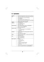
Platform CPU Chipset Memory Hybrid Booster Expansion Slot Graphics Audio LAN Rear Panel I/O - Micro ATX Form Factor: 9.6-in x 8.2-in, 24.4 cm x 20.8 cm - Socket 754 for AMD AthlonTM 64 and Sempron Processors - Supports AMD's Cool 'n' QuietTM Technology (see CAUTION 1) - Chipset capable - ASRock K8NF6G-VSTA | User Manual - Page 7
audio connector - 2 x USB 2.0 headers (support 4 USB 2.0 ports) (see CAUTION 8) - 4Mb AMI BIOS - AMI Legal BIOS - Supports "Plug and Play" - ACPI 1.1 Compliance Wake Up Events - Supports jumperfree - SMBIOS 2.3.1 Support - Drivers, Utilities, AntiVirus Software (Trial Version) - CPU Temperature - ASRock K8NF6G-VSTA | User Manual - Page 8
directly. 8. Power Management for USB 2.0 works fine under Microsoft® Windows® VistaTM 64-bit / VistaTM / XP 64-bit / XP SP1 or SP2 / 2000 SP4. 9. Microsoft® Windows® VistaTM / VistaTM 64-bit driver keeps on updating now. As long as we have the latest driver, we will update it to our website in the - ASRock K8NF6G-VSTA | User Manual - Page 9
Logo For system integrators and users who purchase our motherboard and plan to submit Windows® VistaTM Basic logo, please follow the below table for minimum hardware requirement. CPU Memory VGA Sempron 2500+ 512MB Single Channel* DX9.0 with WDDM Driver * If you use onboard VGA with total system - ASRock K8NF6G-VSTA | User Manual - Page 10
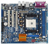
USB 2.0 T: USB2 B: USB3 USB 2.0 T: USB0 B: USB1 Top: RJ-45 ATXPWR1 ATX12V1 Socket 754 RAID RoHS NVIDIA GeForce 6100 / nForce 405 Chipset Super I/O 4Mb BIOS CD1 LAN PHY AUDIO CODEC 1 HD_AUDIO1 PCIE1 K8NF6G-VSTA 15 Floppy Connector (FLOPPY1) 2 CPU Fan Connector (CPU_FAN1) 16 Clear - ASRock K8NF6G-VSTA | User Manual - Page 11
) 10 USB 2.0 Ports (USB23) 11 VGA Port 12 PS/2 Keyboard Port (Purple) 13 PS/2 Mouse Port (Green) * If you use 2-channel speaker, please connect the speaker's plug into "Front Speaker Jack". See the table below for connection details in accordance with the type of speaker you use. TABLE for Audio - ASRock K8NF6G-VSTA | User Manual - Page 12
2. Installation K8NF6G-VSTA is a Micro ATX form factor (9.6-in x 8.2-in, 24.4 cm x 20.8 cm) motherboard. Before you install the motherboard, study the configuration of your chassis to ensure that the motherboard fits into it. Pre-installation Precautions Take note of the following precautions before - ASRock K8NF6G-VSTA | User Manual - Page 13
90° Up Socket Corner CPU Golden Triangle STEP 1: Lift Up The Socket Lever STEP 2 / STEP 3: STEP 4: Match The CPU Golden Triangle Push Down And Lock To The Socket Corner The Socket Lever 2.2 Installation of CPU Fan and Heatsink After you install the CPU into this motherboard, it is necessary - ASRock K8NF6G-VSTA | User Manual - Page 14
2.3 Installation of Memory Modules (DIMM) This motherboard is equipped with two 184-pin DDR (Double notch break The DIMM only fits in one correct orientation. It will cause permanent damage to the motherboard and the DIMM if you force the DIMM into the slot at incorrect orientation. Step 3. Firmly - ASRock K8NF6G-VSTA | User Manual - Page 15
K8NF6G-VSTA motherboard. PCIE Slots: PCIE1 (PCI Express Graphics slot) is used for PCI Express cards with x16 lane width graphics cards. PCIE2 (PCIE x1 slot) is used for PCI Express cards with x1 lane width cards, such as Gigabit LAN card, SATA2 card, etc. PCIE1 (PCI Express Graphics slot) supports - ASRock K8NF6G-VSTA | User Manual - Page 16
memory. If you do not adjust the BIOS setup, the default value of "Share Memory", [Auto], will disable onboard VGA/D-Sub function when the add-on VGA card is inserted to this motherboard. 4. Install the onboard VGA driver step are under Windows® XP environment. If you install other Windows® OS, the - ASRock K8NF6G-VSTA | User Manual - Page 17
enable (see p.10, No. 1) +5V +5VSB +5VSB (standby) for PS/2 or USB wake up events. Note: To select +5VSB, it requires 2 Amp and higher standby not clear the CMOS right after you update the BIOS. If you need to clear the CMOS when you just finish updating the BIOS, you must boot up the system - ASRock K8NF6G-VSTA | User Manual - Page 18
(Blue) (39-pin IDE1, see p.10 No. 6) PIN1 IDE1 connect the blue end to the motherboard connect the black end to the IDE devices 80-conductor ATA 66/100/133 cable Note: Please refer to the instruction of your IDE device vendor for the details. Serial ATAII Connectors (SATAII_1: see p.10, No - ASRock K8NF6G-VSTA | User Manual - Page 19
cable that allows convenient connection and control of audio devices. 1. High Definition Audio supports Jack Sensing, but the panel wire on the chassis must support HDA to function correctly. Please follow the instruction in our manual and chassis manual to install your system. 2. If you use AC - ASRock K8NF6G-VSTA | User Manual - Page 20
to the ground pin. Though this motherboard provides 4-Pin CPU fan (Quiet Fan) support, the 3-Pin CPU fan still can work successfully even without the fan speed control function. If you plan to connect the 3-Pin CPU fan to the CPU fan connector on this motherboard, please connect it to Pin 1-3. Pin - ASRock K8NF6G-VSTA | User Manual - Page 21
Connect a Game cable to this header if the Game port bracket is installed. RRXD1 DDTR#1 DDSR#1 CCTS#1 1 RRI#1 RRTS#1 GND TTXD1 DDCD#1 This COM1 header supports a serial port module. 21 - ASRock K8NF6G-VSTA | User Manual - Page 22
guide. Some default setting of SATAII hard disks may not be at SATAII mode, which operate with the best performance. In order to enable SATAII function, please follow the below instruction website for details: http://www.hitachigst.com/hdd/support/download.htm The above examples are just for your - ASRock K8NF6G-VSTA | User Manual - Page 23
-on and in working condition. 2.11 Driver Installation Guide To install the drivers to your system, please insert the support CD to your optical drive first. Then, the drivers compatible to your system can be auto-detected and listed on the support CD driver page. Please follow the order from up - ASRock K8NF6G-VSTA | User Manual - Page 24
. 1. Insert HDMR card to HDMR slot on this motherboard. Please make sure that the HDMR card is completely seated on the slot. 2. Install HDMR card driver from our support CD to your system. 3. Reboot your system. 2.13 Installing Windows® 2000 / XP / XP 64-bit / VistaTM / VistaTM 64-bit Without RAID - ASRock K8NF6G-VSTA | User Manual - Page 25
refer to the BIOS RAID installation guide in the following path in the Support CD: .. \ RAID Installation Guide STEP 4: Install Windows® 2000 / Windows® XP / Windows® XP-64bit OS on your system. After step1, 2, 3, you can start to install Windows® 2000 / Windows® XP / Windows® XP 64-bit OS - ASRock K8NF6G-VSTA | User Manual - Page 26
Mode" to [RAID] in BIOS first. Then, please set the RAID configuration by using the Windows RAID installation guide in the following path in the Support CD: .. \ RAID Installation Guide 2.15 Untied Overclocking Technology This motherboard supports Untied Overclocking Technology, which means during - ASRock K8NF6G-VSTA | User Manual - Page 27
the BIOS SETUP UTILITY to configure your system. The Flash Memory on the motherboard stores the BIOS SETUP UTILITY. You may run the BIOS SETUP off and then back on. Because the BIOS software is constantly being updated, the following BIOS setup screens and descriptions are for reference purpose - ASRock K8NF6G-VSTA | User Manual - Page 28
Boot Security Exit System Overview System Time System Date [17:00:09] [Wed 07/12/2006] BIOS Version : K8NF6G-VSTA BIOS P1.0 Processor Type : AMD Athlon(tm) 64 Processor 3400+ (64bit supported) Processor Speed : 2200 MHz Microcode Update : F7A/3A L1 Cache Size : 128KB L2 Cache Size : 512KB Total - ASRock K8NF6G-VSTA | User Manual - Page 29
may set the configurations for the following items: CPU Configuration, Chipset Configuration, ACPI Configuration, IDE Configuration, PCIPnP Configuration, Floppy Configuration, SuperIO Configuration, and USB Configuration. Main BIOS SETUP UTILITY Advanced H/W Monitor Boot Security Exit Advanced - ASRock K8NF6G-VSTA | User Manual - Page 30
. However, it is recommended to keep the default value for system stability. BIOS SETUP UTILITY BIOS SETUP UTILITY Advanced CPU Configuration Overclock Mode CPU Frequency (MHz) PCIE Frequency (MHz) Boot Failure Guard CPU/LDT Spread Spectrum PCIE Spread Spectrum SATA Spread Spectrum Cool' n' Quiet - ASRock K8NF6G-VSTA | User Manual - Page 31
show when "Multiplier/Voltage Change" is set to [Manual]; otherwise, it will be hidden. The range of the value depends on the CPU you adopt on this motherboard. However, for safety and system stability, it is not recommended to adjust the value of this item. Memory Clock This item can be set by the - ASRock K8NF6G-VSTA | User Manual - Page 32
accross nodes, decreasing access contention. 3.3.2 Chipset Configuration BIOS SETUP UTILITY Advanced Chipset Settings Onboard LAN Onboard HD Audio Front Panel Controller Share Memory Primary Graphics Adapter [Enabled] [Auto] [Auto] [Auto] [PCI] CPU-NB Link Speed CPU-NB Kink Width DRAM Voltage - ASRock K8NF6G-VSTA | User Manual - Page 33
RAM Use this item to select whether to auto-detect or disable the Suspend-toRAM feature. Select [Auto] will enable this feature if the OS supports it. If you set this item to [Disabled], the function "Repost Video ] if you plan to use this motherboard to submit Windows® VistaTM certification. 33 - ASRock K8NF6G-VSTA | User Manual - Page 34
BIOS SETUP UTILITY IDE Configuration OnBoard IDE Controller OnBoard SATA Controller SATA Operation Mode IDE Master IDE Slave SATAII 1 SATAII 2 [Enabled] [Enabled] [non-RAID] [Hard Disk] [Not Detected] [Not Detected] [Not Detected RAID functions in NVIDIA BIOS / Windows RAID Utility. IDE Device - ASRock K8NF6G-VSTA | User Manual - Page 35
device. [Auto]: Select [Auto] to automatically detect the hard disk drive. After selecting the hard disk information into BIOS, use a disk utility, such as FDISK, the LBA/Large mode for a hard disk > 512 MB under DOS and Windows; for Netware and UNIX user, select [Disabled] to disable the LBA/Large - ASRock K8NF6G-VSTA | User Manual - Page 36
Enabled]. 32Bit Data Transfer Use this item to enable 32-bit access to maximize the IDE hard disk data transfer rate. 3.3.5 PCIPnP Configuration BIOS SETUP UTILITY Advanced Advanced PCI / PnP Settings WARNING: Setting wrong values in below sections may cause system to malfunction. Value in units - ASRock K8NF6G-VSTA | User Manual - Page 37
Load Defaults Save and Exit Exit v02.54 (C) Copyright 1985-2003, American Megatrends, Inc. 3.3.7 Super IO Configuration BIOS SETUP UTILITY Advanced Configure Super IO Chipset OnBoard Floppy Controller Serial Port Address Infrared Port Address Parallel Port Address Parallel Port Mode EPP Version - ASRock K8NF6G-VSTA | User Manual - Page 38
it. Configuration options: [Disabled], [300], and [330]. 3.3.8 USB Configuration BIOS SETUP UTILITY Advanced USB Configuration USB Controller USB 2.0 Support Legacy USB Support [Enabled] [Enabled] [Disabled] To enable or disable the onboard USB controllers. +F1 F9 F10 ESC Select Screen Select - ASRock K8NF6G-VSTA | User Manual - Page 39
-detect; if there is no USB device connected, "Auto" option will disable the legacy USB support. 3.4 Hardware Health Event Monitoring Screen In this section, it allows you to monitor the status of the hardware on your system, including the parameters of the CPU temperature, motherboard temperature - ASRock K8NF6G-VSTA | User Manual - Page 40
v02.54 (C) Copyright 1985-2003, American Megatrends, Inc. 3.5.1 Boot Settings Configuration BIOS SETUP UTILITY Boot Boot Settings Configuration Boot From Network Bootup Num-Lock [Disabled] [On] To enable or disable the boot from network feature. +F1 F9 F10 ESC Select Screen Select Item Change - ASRock K8NF6G-VSTA | User Manual - Page 41
you may set or change the supervisor/user password for the system. For the user password, you may also clear it. BIOS SETUP UTILITY Main Advanced H/W Monitor Boot Security Exit Security Settings Supervisor Password : Not Installed User Password : Not Installed Change Supervisor Password - ASRock K8NF6G-VSTA | User Manual - Page 42
and exit setup?" Select [OK] to save the changes and exit the BIOS SETUP UTILITY. Discard Changes and Exit When you select this option, it message, "Discard changes and exit setup?" Select [OK] to exit the BIOS SETUP UTILITY without saving any changes. Discard Changes When you select this option - ASRock K8NF6G-VSTA | User Manual - Page 43
menus. 4.2.2 Drivers Menu The Drivers Menu shows the available devices drivers if the system detects the installed devices. Please install the necessary drivers to activate the devices. 4.2.3 Utilities Menu The Utilities Menu shows the applications software that the motherboard supports. Click on - ASRock K8NF6G-VSTA | User Manual - Page 44
feature, please make sure to install "AMD Processor Driver" from the "Support CD" first. If you are using Windows® 2000/XP operating system, please follow the instruction below to enable AMD's Cool 'n' QuietTM technology: 1. From the Windows® 2000/XP operating system, click the Start button. Select
-
 1
1 -
 2
2 -
 3
3 -
 4
4 -
 5
5 -
 6
6 -
 7
7 -
8
-
9
-
10
-
11
-
12
-
13
-
14
-
15
-
16
-
17
-
18
-
19
-
20
-
21
-
22
-
23
-
24
-
25
-
26
-
27
-
28
-
29
-
30
-
31
-
32
-
33
-
34
-
35
-
36
-
37
-
38
-
39
-
40
-
41
-
42
-
43
-
44
 |
 |
1
K8NF6G-VSTA
User Manual
Version 1.2
Published December 2006
Copyright©2006 ASRock INC. All rights reserved.