ASRock M266A R3.0 User Manual - Page 14
CD-ROM, DVD-ROM, TV
 |
View all ASRock M266A R3.0 manuals
Add to My Manuals
Save this manual to your list of manuals |
Page 14 highlights
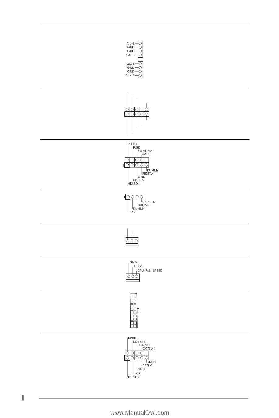
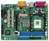
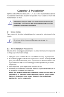
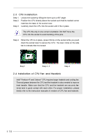
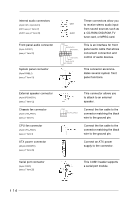
Internal audio connectors (4-pin CD1, 4-pin AUX1) (CD1: see p.7 item 27) (AUX1: see p.7 item 26) These connectors allow you CD1 to receive stereo audio input from sound sources such as AUX1 a CD-ROM, DVD-ROM, TV tuner card, or MPEG card. Front panel audio connector (9-pin AUDIO1) (see p.7 item 22) System panel connector (9-pin PANEL1) (see p.7 item 13) GND +5VA BACKOUT-R BACKOUT-L 1 A U D - O U T- L GND A U D - O U T- R MIC-POWER MIC This is an interface for front panel audio cable that allows convenient connection and control of audio devices. This connector accommodates several system front panel functions. External speaker connector (4-pin SPEAKER 1) (see p.7 item 12) Chassis fan connector (3-pin CHA_FAN1) (see p.7 item 11) CPU fan connector (3-pin CPU_FAN1) (see p.7 item 3) ATX power connector (20-pin ATXPWR1) (see p.7 item 29) This connector allows you to attach to an external speaker. GND +12V CHA_FAN_SPEED Connect the fan cable to the connector matching the black wire to the ground pin. Connect the fan cable to the connector matching the black wire to the ground pin. Connect an ATX power supply to the connector. Serial port connector (9-pin COM1) (see p.7 item 20) This COM1 header supports a serial port module. 14
-
 1
1 -
2
-
3
-
4
-
5
-
6
-
7
-
8
-
 9
9 -
 10
10 -
 11
11 -
 12
12 -
 13
13 -
 14
14 -
 15
15 -
 16
16 -
 17
17 -
 18
18 -
 19
19 -
20
-
21
-
22
-
23
-
24
-
25
-
26
-
27
 |
 |