ASRock M3A UCC User Manual
ASRock M3A UCC Manual
 |
View all ASRock M3A UCC manuals
Add to My Manuals
Save this manual to your list of manuals |
ASRock M3A UCC manual content summary:
- ASRock M3A UCC | User Manual - Page 1
M3A UCC User Manual Version 1.1 Published September 2011 Copyright©2011 ASRock INC. All rights reserved. 1 - ASRock M3A UCC | User Manual - Page 2
purchaser for backup purpose, without written consent of ASRock Inc. Products and corporate names appearing in this manual may or may not be registered trademarks or copyrights USA ONLY The Lithium battery adopted on this motherboard contains Perchlorate, a toxic substance controlled in Perchlorate - ASRock M3A UCC | User Manual - Page 3
Motherboard Layout 10 1.4 I/O Panel 11 2 . Installation 12 Pre-installation Precautions 12 2.1 CPU Installation 13 2.2 Installation of CPU SATA / SATAII HDDs .... 23 2.10 SATA / SATAII HDD Hot Plug Feature and Operation Guide ..... 24 2.11 Driver Installation Guide 26 2.12 Installing Windows® - ASRock M3A UCC | User Manual - Page 4
BIOS Menu Bar 31 3.1.2 Navigation Keys 32 3.2 Main Screen 32 3.3 OC Tweaker Screen 33 3.4 Advanced Screen 40 3.4.1 CPU Configuration 41 3.4.2 Chipset 4 . Software Support 53 4.1 Install Operating System 53 4.2 Support CD Information 53 4.2.1 Running Support CD 53 4.2.2 Drivers Menu 53 - ASRock M3A UCC | User Manual - Page 5
of this manual occur, the updated version will be available on ASRock website without further notice. You may find the latest VGA cards and CPU support lists on ASRock website as well. ASRock website http://www.asrock.com If you require technical support related to this motherboard, please visit - ASRock M3A UCC | User Manual - Page 6
Platform CPU Chipset Memory Expansion Slot Audio LAN Rear Panel I/O Connector - ATX Form Factor: 12.0-in x 7.8-in, 30.5 cm x 19.8 cm - Support for Socket AM3 processors: AMD PhenomTM II X4 / X3 / X2 (except 920 / 940) / Athlon II X4 / X3 / X2 / Sempron processors - Six-Core CPU Ready - Supports UCC - ASRock M3A UCC | User Manual - Page 7
audio connector - 2 x USB 2.0 headers (support 4 USB 2.0 ports) (see CAUTION 7) BIOS Feature - 4Mb AMI BIOS - AMI Legal BIOS - Supports "Plug and Play" - ACPI 1.1 Compliance Wake Up Events - Supports jumperfree - SMBIOS 2.3.1 Support - CPU Voltage Multi-adjustment Support CD - Drivers - ASRock M3A UCC | User Manual - Page 8
memory speed is supported depends on the AM3 CPU you adopt. If you want to adopt DDR3 1800/1600 memory module on this motherboard, please refer to the memory support list on our website for the compatible memory modules. ASRock website http://www.asrock.com 5. Due to the chipset limitation, if you - ASRock M3A UCC | User Manual - Page 9
BIOS update tool allows you to update system BIOS without entering operating systems first like MS-DOS or Windows®. With this utility, you can press key during the POST or press key to BIOS setup menu to access ASRock Instant Flash. Just launch this tool and save the new BIOS file - ASRock M3A UCC | User Manual - Page 10
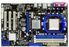
1 IR1 PWR_FAN1 PCIE1 AMD 480X CrossFire Chipset Support 6-Core CPU RoHS PCIE2 CMOS BATTERY Designed in Taipei Super I/O AUDIO CODEC HD_AUDIO1 1 FLOPPY1 PCIE3 CLRCMOS1 1 M3A UCC PCI1 PCI2 ErP/EuP Ready ATI SB600 Chipset PCI3 CHA_FAN1 SPEAKER1 1 4Mb BIOS USB_PW1 PANEL 1 1 PLED - ASRock M3A UCC | User Manual - Page 11
header. After restarting your computer, you will find "VIA HD Audio Deck" tool on your system. Please follow below instructions according to the OS you install. For Windows® XP / XP 64-bit OS: Please click "VIA HD Audio Deck" icon , and click "Speaker". Then you are allowed to select "2 Channel - ASRock M3A UCC | User Manual - Page 12
, peripherals, and/or components. 1. Unplug the power cord from the wall socket before touching any component. 2. To avoid damaging the motherboard components due to static electricity, NEVER place your motherboard directly on the carpet or the like. Also remember to use a grounded wrist strap - ASRock M3A UCC | User Manual - Page 13
Socker Corner Small Triangle STEP 2 / STEP 3: Match The CPU Golden Triangle To The Socket Corner Small Triangle STEP 4: Push Down And Lock The Socket Lever 2.2 Installation of CPU Fan and Heatsink After you install the CPU into this motherboard, it is necessary to install a larger heatsink and - ASRock M3A UCC | User Manual - Page 14
2.3 Installation of Memory Modules (DIMM) This motherboard provides four 240-pin DDR3 (Double Data Rate 3) DIMM slots, and supports Dual Channel Memory Technology. For dual channel configuration, you always need to install identical (the same brand, speed, size and chiptype) DDR3 DIMM pair in - ASRock M3A UCC | User Manual - Page 15
matches the break on the slot. notch break notch break The DIMM only fits in one correct orientation. It will cause permanent damage to the motherboard and the DIMM if you force the DIMM into the slot at incorrect orientation. Step 3. Firmly insert the DIMM into the slot until the retaining - ASRock M3A UCC | User Manual - Page 16
slot) is used for PCI Express cards with x1 lane width cards, such as Gigabit LAN card, SATA2 card, etc. PCIE2 (PCIE x16 slot) is used for PCI Express cards with x16 lane width graphics cards. Installing an expansion card Step 1. Before installing the expansion card, please make sure that the power - ASRock M3A UCC | User Manual - Page 17
+5V_DUAL, USB devices can wake up the system under S3 (Suspend to RAM) state. To support ErP/EuP requirement, please set this jumper to +5V. USB_PW1 (see p. clear the CMOS right after you update the BIOS. If you need to clear the CMOS when you just finish updating the BIOS, you must boot up the - ASRock M3A UCC | User Manual - Page 18
to the motherboard connect the black end to the IDE devices 80-conductor ATA 66/100/133 cable Note: Please refer to the instruction of your IDE SATAII_1 (PORT0) These four Serial ATAII (SATAII) connectors support SATAII or SATA hard disk for internal storage devices. The current SATAII interface - ASRock M3A UCC | User Manual - Page 19
cable that allows convenient connection and control of audio devices. 1. High Definition Audio supports Jack Sensing, but the panel wire on the chassis must support HDA to function correctly. Please follow the instruction in our manual and chassis manual to install your system. 2. If you use AC - ASRock M3A UCC | User Manual - Page 20
4-Pin CPU fan (Quiet Fan) support, the 3-Pin CPU fan still can work successfully even without the fan speed control function. If you plan to connect the 3-Pin CPU fan to the CPU fan connector on this motherboard, please connect it to Pin 1-3. Pin 1-3 Connected 3-Pin Fan Installation ATX Power - ASRock M3A UCC | User Manual - Page 21
ATX 12V Power Connector (4-pin ATX12V1) (see p.10 No. 2) Please note that it is necessary to connect a power supply with ATX 12V plug to this connector. Failing to do so will cause power up failure. 21 - ASRock M3A UCC | User Manual - Page 22
guide. Some default setting of SATAII hard disks may not be at SATAII mode, which operate with the best performance. In order to enable SATAII function, please follow the below instruction If pin 3 and pin 4 are shorted, SATA 1.5Gb/s will be enabled. On the other .com/hdd/support/download.htm The - ASRock M3A UCC | User Manual - Page 23
This motherboard adopts AMD SB600 south bridge chipset that supports Serial ATA (SATA) / Serial ATAII (SATAII) hard disks and RAID (RAID 0, RAID 1 and RAID 10) functions. You may install SATA / SATAII hard disks on this motherboard for internal storage devices. This section will guide you - ASRock M3A UCC | User Manual - Page 24
make sure the SATA / SATAII driver is installed into system properly. The latest SATA / SATAII driver is available on our support website: www.asrock.com 4. Make sure to use the SATA power cable & data cable, which are from our motherboard package. 5. Please follow below instructions step by step - ASRock M3A UCC | User Manual - Page 25
follow below instruction sequence to process the Hot Plug, improper procedure will cause the SATA / SATAII HDD damage and data loss. Step 1 Please connect SATA power cable 1x4-pin end Step 2 Connect SATA data cable to (White) to the power supply 1x4-pin cable. the motherboard's SATAII connector - ASRock M3A UCC | User Manual - Page 26
functions, please follow below steps. STEP 1: Set up BIOS. A. Enter BIOS SETUP UTILITY Advanced screen Storage Configuration. B. Set the "SATA Operation Mode" option to [RAID]. STEP 2: Make a SATA / SATAII Driver Diskette. A. Insert the ASRock Support CD into your optical drive to boot your - ASRock M3A UCC | User Manual - Page 27
rebuild) RAID functions on SATA / SATAII HDDs, you still need to set up "SATA Operation Mode" to [RAID] in BIOS first. Then, please set the RAID configuration by using the Windows RAID installation guide in the following path in the Support CD: .. \ RAID Installation Guide NOTE2. Currently, if you - ASRock M3A UCC | User Manual - Page 28
on SATA / SATAII HDD. For the proper operating procedures of creating JBOD, please refer to the BIOS RAID installation guide part of the document in the following path in the Support CD: .. \ RAID Installation Guide JBOD function on this motherboard is only supported with single SATA / SATAII - ASRock M3A UCC | User Manual - Page 29
. Select the driver to install according to the OS you install. (Select "ATI AHCI Compatible RAID Controllerx86 platform" for Windows® XP, or "ATI AHCI Compatible RAID Controller-x64 platform" for Windows® XP 64-bit.) Using SATA / SATAII HDDs without NCQ and Hot Plug functions STEP 1: Set up BIOS - ASRock M3A UCC | User Manual - Page 30
Technology This motherboard supports Untied Overclocking Technology, which means during overclocking, FSB enjoys better margin due to fixed PCI / PCIE buses. Before you enable Untied Overclocking function, please enter "Overclock Mode" option of BIOS setup to set the selection from [Auto] to [Manual - ASRock M3A UCC | User Manual - Page 31
motherboard stores the BIOS SETUP UTILITY. You may run the BIOS SETUP UTILITY when you start up the computer. Please press or during the Power-On-Self-Test (POST) to enter the BIOS on. Because the BIOS software is constantly being updated, the following BIOS setup screens and descriptions - ASRock M3A UCC | User Manual - Page 32
Monitor System Overview System Time System Date [17:00:09] [Fri 04/23/2010] BIOS Version : M3A UCC P1.00 Processor Type : AMD Phenom(tm) II X3 705e Processor (64bit) Processor Speed : 2500MHz Microcode Update : 100F42/1000086 L1 Cache Size : 384KB L2 Cache Size : 1536KB L3 Cache Size : 6144KB - ASRock M3A UCC | User Manual - Page 33
. BIOS SETUP UTILITY Main OC Tweaker Advanced H/W Monitor Boot Security Exit EZ Overclocking Load Optimized CPU OC Setting [Press Enter] CPU Configuration Overclock Mode CPU Frequency (MHZ) PCIE Frequency (MHz) Spread Spectrum Boot Failure Guard Boot Failure Guard Count ASRock UCC CPU Active - ASRock M3A UCC | User Manual - Page 34
, which means you can enjoy the upgrade CPU performance with a better price. Please be noted that UCC feature is supported with AM3 CPU only, and in addition, not every AM3 CPU can support this function because some CPU's hidden core may be malfunctioned. CPU Active Core Control This allows you to - ASRock M3A UCC | User Manual - Page 35
Bit] and [16 Bit]. CPU Thermal Throttle Use this item to enable CPU internal thermal control mechanism to keep the CPU from overheated. Configuration options: This item can be set by the code using [Auto]. You can set one of the standard values as listed: [400MHz DDR3_800], [533MHz DDR3_1066], [ - ASRock M3A UCC | User Manual - Page 36
Memory Timing BIOS SETUP UTILITY OC Tweaker Memory Timing Memory Controller Mode Power Down Enable Bank Interleaving Channel Interleaving CAS Latency (CL) 9 TRCD 12 TRP 12 TRAS 30 - ASRock M3A UCC | User Manual - Page 37
TRRD Use this to adjust TRRD values. Configuration options: [Auto], [4CLK] to [7CLK]. The default value is [Auto]. TWTR Use this to adjust TWTR values. Configuration options: [Auto], [4CLK] to [7CLK]. The default value is [Auto]. TWR Use this to adjust TWR values. Configuration options: [Auto], [ - ASRock M3A UCC | User Manual - Page 38
CHA ADDR/CMD Setup Use this to adjust values for CHA ADDR/CMD Setup feature. Configuration options: [Auto], [1/2CLK] and [1CLK]. The default value is [Auto]. CHA CS/ODT Delay Use this to adjust values for CHA CS/ODT Delay feature. Configuration options: [Auto], [No Delay], [1/64CLK] to [31/64CLK]. - ASRock M3A UCC | User Manual - Page 39
this to adjust values for CHB Processor ODT. Configuration options: [Auto], [240 ohms], [120 ohms] and [60 ohms]. The default value is [Auto]. Chipset Settings NB Voltage Use this to select NB voltage. Configuration options: [Auto], [1.247V] to [1.320V]. The default value is [Auto]. PCIE Voltage Use - ASRock M3A UCC | User Manual - Page 40
to malfunction. ASRock Instant Flash ASRock Instant Flash is a BIOS flash utility embedded in Flash ROM. This convenient BIOS update tool allows you to update system BIOS without entering operating systems first like MS-DOS or Windows®. Just launch this tool and save the new BIOS file to your USB - ASRock M3A UCC | User Manual - Page 41
provided by AMD-V. The default value is [Enabled]. Configuration options: [Enabled] and [Disabled]. Enhance Halt State All processors support the Halt State (C1). The C1 state is supported through the native processor instructions HLT and MWAIT and requires no hardware support from the chipset. In - ASRock M3A UCC | User Manual - Page 42
3.4.2 Chipset Configuration BIOS SETUP UTILITY Advanced Chipset Settings Onboard HD Audio Front Panel OnBoard Lan Dr. LAN Link speed : 10Mbps Primary Graphics Adapter [Auto] [Auto] [Auto] [Enabled] [PCI] Auto/Enable/Disable Onboard HD Audio. +F1 F9 F10 ESC Select Screen Select Item Change - ASRock M3A UCC | User Manual - Page 43
3.4.3 ACPI Configuration BIOS SETUP UTILITY Advanced ACPI Settings Suspend To RAM Check Ready Bit Away Mode Support Restore on AC / Power Loss Ring-In Power On PCI Devices Power On PS set this option to [Enabled] if you plan to use this motherboard to submit Windows® VistaTM certification. 43 - ASRock M3A UCC | User Manual - Page 44
Onboard SATA Controller Use this item to enable or disable the "Onboard SATA Controller" feature. SATA Operation Mode Use this item to adjust SATA example in the following instruction, which can be applied to the configurations of "IDE1 Slave" as well. BIOS SETUP UTILITY Advanced IDE Master - ASRock M3A UCC | User Manual - Page 45
After selecting the hard disk information into BIOS, use a disk utility, such as FDISK, to partition Mode Use this item to select the LBA/Large mode for a hard disk > 512 MB under DOS and Windows; for Netware and UNIX user, select [Disabled] to disable the LBA/Large mode. Block (Multi-Sector Transfer - ASRock M3A UCC | User Manual - Page 46
recommended to keep the default value unless the installed PCI expansion cards' specifications require other settings. PCI IDE BusMaster Use this item In this section, you may configure the type of your floppy drive. BIOS SETUP UTILITY Advanced Floppy Configuration Floppy A [1.44 MB 312"] Select - ASRock M3A UCC | User Manual - Page 47
Advanced Configure Super IO Chipset OnBoard Floppy Controller Serial Port Address Infrared Port Address Parallel Port Address Parallel Port Mode EPP Version ECP Mode DMA Channel Parallel Port IRQ [Enabled] [3F8 / IRQ4] [Disabled] [378] [ECP + EPP] [1.9] [DMA3] [IRQ7] Allow BIOS to Enable or - ASRock M3A UCC | User Manual - Page 48
Use this item to enable or disable the USB 2.0 support. Legacy USB Support Use this option to select legacy support for USB devices. There are four configuration options: [Enabled], [Auto], [Disabled] and [BIOS Setup Only]. The default value is [Enabled]. Please refer to below descriptions for - ASRock M3A UCC | User Manual - Page 49
to monitor the status of the hardware on your system, including the parameters of the CPU temperature, motherboard temperature, CPU fan speed, chassis fan speed, and the critical voltage. BIOS SETUP UTILITY Main OC Tweaker Advanced H/W Monitor Boot Security Exit Hardware Health Event Monitoring - ASRock M3A UCC | User Manual - Page 50
this section, it will display the available devices on your system for you to configure the boot settings and the boot priority. BIOS SETUP UTILITY Main OC Tweaker Advanced H/W Monitor Boot Security Exit Boot Settings Boot Settings Configuration Configure Settings during System Boot. 1st Boot - ASRock M3A UCC | User Manual - Page 51
this section, you may set or change the supervisor/user password for the system. For the user password, you may also clear it. BIOS SETUP UTILITY Main OC Tweaker Advanced H/W Monitor Boot Security Exit Security Settings Supervisor Password : Not Installed User Password : Not Installed Change - ASRock M3A UCC | User Manual - Page 52
Advanced H/W Monitor Boot Security Exit Exit Options Save Changes and Exit Discard Changes and Exit Discard Changes Load BIOS Defaults Load Performance Setup Default (IDE/SATA) Load Performance Setup AHCI Mode Load Performance Setup RAID Mode Load Power Saving Setup Default Exit system setup - ASRock M3A UCC | User Manual - Page 53
install the necessary drivers to activate the devices. 4.2.3 Utilities Menu The Utilities Menu shows the applications software that the motherboard supports. Click on a specific item then follow the installation wizard to install it. 4.2.4 Contact Information If you need to contact ASRock or want to
-
 1
1 -
 2
2 -
 3
3 -
 4
4 -
 5
5 -
 6
6 -
 7
7 -
8
-
9
-
10
-
11
-
12
-
13
-
14
-
15
-
16
-
17
-
18
-
19
-
20
-
21
-
22
-
23
-
24
-
25
-
26
-
27
-
28
-
29
-
30
-
31
-
32
-
33
-
34
-
35
-
36
-
37
-
38
-
39
-
40
-
41
-
42
-
43
-
44
-
45
-
46
-
47
-
48
-
49
-
50
-
51
-
52
-
53
 |
 |

1
M3A UCC
User Manual
Version 1.1
Published September 2011
Copyright©2011 ASRock INC. All rights reserved.