ASRock M3A785GM-LE/128M User Manual
ASRock M3A785GM-LE/128M Manual
 |
View all ASRock M3A785GM-LE/128M manuals
Add to My Manuals
Save this manual to your list of manuals |
ASRock M3A785GM-LE/128M manual content summary:
- ASRock M3A785GM-LE/128M | User Manual - Page 1
M3A785GM-LE/128M User Manual Version 1.0 Published October 2009 Copyright©2009 ASRock INC. All rights reserved. 1 - ASRock M3A785GM-LE/128M | User Manual - Page 2
any form or by any means, except duplication of documentation by the purchaser for backup purpose, without written consent of ASRock Inc. Products and corporate names appearing in this manual may or may not be registered trademarks or copyrights of their respective companies, and are used only for - ASRock M3A785GM-LE/128M | User Manual - Page 3
12 SATA / SATAII HDD Hot Plug Feature and Operation Guide ..... 31 2.13 Driver Installation Guide 33 2.14 Installing Windows® 7 / 7 64-bit / VistaTM / VistaTM 64-bit / XP / XP 64-bit With RAID Functions 33 2.14.1 Installing Windows® XP / XP 64-bit With RAID Functions 33 2.14.2 Installing Windows - ASRock M3A785GM-LE/128M | User Manual - Page 4
BIOS Menu Bar 38 3.1.2 Navigation Keys 39 3.2 Main Screen 39 3.3 OC Tweaker Screen 40 3.4 Advanced Screen 47 3.4.1 CPU Screen 60 4 . Software Support 61 4.1 Install Operating System 61 4.2 Support CD Information 61 4.2.1 Running Support CD 61 4.2.2 Drivers Menu 61 4.2.3 Utilities - ASRock M3A785GM-LE/128M | User Manual - Page 5
the model you are using. www.asrock.com/support/index.asp 1.1 Package Contents 1 x ASRock M3A785GM-LE/128M Motherboard (Micro ATX Form Factor: 9.6-in x 7.8-in, 24.4 cm x 19.8 cm) 1 x ASRock M3A785GM-LE/128M Quick Installation Guide 1 x ASRock M3A785GM-LE/128M Support CD 1 x Ultra ATA 66/100/133 - ASRock M3A785GM-LE/128M | User Manual - Page 6
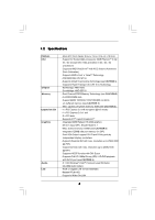
1.2 Specifications Platform CPU Chipset Memory Expansion Slot Graphics Audio LAN - Micro ATX Form Factor: 9.6-in x 7.8-in, 24.4 cm x 19.8 cm - Support for Socket AM3 processors: AMD PhenomTM II X4 / X3 / X2 (except 920 / 940) and Athlon II X4 / X3 / X2 processors - Supports AMD OverDriveTM with - ASRock M3A785GM-LE/128M | User Manual - Page 7
ACPI 1.1 Compliance Wake Up Events - Supports jumperfree - SMBIOS 2.3.1 Support - VCCM, NB Voltage Multi-adjustment - Supports Smart BIOS - Drivers, Utilities, AntiVirus Software (Trial Version), AMD OverDriveTM Utility, AMD Live! Explorer, AMD Fusion, ASRock Software Suite (CyberLink DVD Suite and - ASRock M3A785GM-LE/128M | User Manual - Page 8
. 3. Whether 1600MHz memory speed is supported depends on the AM3 CPU you adopt. If you want to adopt DDR3 1600 memory module on this motherboard, please refer to the memory support list on our website for the compatible memory modules. ASRock website http://www.asrock.com 4. Due to the operating - ASRock M3A785GM-LE/128M | User Manual - Page 9
"SATAII Hard Disk Setup Guide" on page 28 to 64-bit / VistaTM / XP 64-bit / XP SP1 or SP2. 9. It is a user-friendly ASRock ASRock website: http://www.asrock.com 11. ASRock Instant Flash is a BIOS flash utility embedded in Flash ROM. This convenient BIOS update tool allows you to update system BIOS - ASRock M3A785GM-LE/128M | User Manual - Page 10
motherboard functions properly and unplug the power cord, then plug it back again. To improve heat dissipation, remember to spray thermal grease between the CPU and the heatsink when you install the PC system. 15. EuP, stands for Energy Using Product, was a provision regulated by European Union to - ASRock M3A785GM-LE/128M | User Manual - Page 11
DVD playback is only supported under Windows® 7 / 7 64-bit / VistaTM / VistaTM 64-bit OS. If you install Windows® XP / XP 64-bit OS, the function of 1080p Blu-ray (BD) / HD-DVD playback is not available, please visit our website for AMD 785G VGA driver update in the future. ASRock website http://www - ASRock M3A785GM-LE/128M | User Manual - Page 12
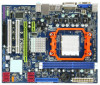
AUDIO CODEC Super I/O CD1 1 HD_AUDIO1 LPT1 1 PCIE1 AMD 785G Chipset Hybrid CrossFire PCIE2 M3A785GM-LE/128M IDE1 PWR_FAN1 SATAII_4 SATAII_5 SATAII_6 (PORT 3) (PORT 4) (PORT 5) RoHS PCI1 IR1 1 FLOPPY1 PCI2 USB10_11 1 AMD SB710 Chipset SPEAKER1 1 PLED PWRBTN PANEL 1 1 HDLED RESET 8Mb BIOS - ASRock M3A785GM-LE/128M | User Manual - Page 13
Orange 100Mbps connection On Link Green 1Gbps connection LAN Port To enable Multi-Streaming function, you need to connect a front panel audio cable to the front panel audio header. Please refer to below steps for the software setting of Multi-Streaming. For Windows® XP: After restarting your - ASRock M3A785GM-LE/128M | User Manual - Page 14
2. Installation This is a Micro ATX form factor (9.6-in x 7.8-in, 24.4 cm x 19.8 cm) motherboard. to the motherboard, peripherals, and/or components. 1. Unplug the power cord from the wall socket before touching any component. 2. To avoid damaging the motherboard components due to static electricity, - ASRock M3A785GM-LE/128M | User Manual - Page 15
. Make sure that the CPU and the heatsink are securely fastened and in good contact with each other. Then connect the CPU fan to the CPU FAN connector (CPU_FAN1, see Page 12, No. 6). For proper installation, please kindly refer to the instruction manuals of the CPU fan and the heatsink. 15 - ASRock M3A785GM-LE/128M | User Manual - Page 16
2.3 Installation of Memory Modules (DIMM) M3A785GM-LE/128M motherboard provides two 240-pin DDR3 (Double Data Rate 3) DIMM slots, and supports Dual Channel Memory Technology. For dual channel configuration, you always need to install two identical (the same brand, speed, size and chip-type) memory - ASRock M3A785GM-LE/128M | User Manual - Page 17
2.4 Expansion Slots (PCI and PCI Express Slots) There are 2 PCI slots and 2 PCI Express slots on this motherboard. PCI slots: PCI slots are used to install expansion cards that have the 32-bit PCI interface. PCIE slots: PCIE1 (PCIE x1 slot; Green) is used for PCI Express cards with x1 lane width - ASRock M3A785GM-LE/128M | User Manual - Page 18
the D-Sub monitor cable to the VGA/D-Sub port on the I/O panel. VGA/D-Sub port VGA/DVI-D port 2. If you have installed onboard VGA driver from our support CD to your system already, you can freely enjoy the benefits of dual monitor function after your system boots. If you haven't installed onboard - ASRock M3A785GM-LE/128M | User Manual - Page 19
memory. If you do not adjust the BIOS setup, the default value of "Share Memory", [Auto], will disable VGA/D-Sub function when the add-on VGA card is inserted to this motherboard. 4. Install the onboard VGA driver and the add-on PCI Express VGA card driver to your system. If you have installed - ASRock M3A785GM-LE/128M | User Manual - Page 20
function with this motherboard, you need to adopt the monitor that supports HDCP function as well. Therefore, you can enjoy the superior display quality with high-definition HDCP encryption contents. Please refer to below instruction for more details about HDCP function. What is HDCP? HDCP stands - ASRock M3A785GM-LE/128M | User Manual - Page 21
* POWERCOLOR HD2400 XT Catalyst 8.512 256MB DDR3 RADEON HD3450 POWERCOLOR AX3450 Catalyst 8.512 256MD2-S * Currently, RADEON HD2400XT series graphics cards are only supported with AMD Phenom CPU. Please visit our website for the future driver update and the latest information. Enjoy the - ASRock M3A785GM-LE/128M | User Manual - Page 22
used only for identification or explanation and to the owners' benefit, without intent to infringe. * For further information of ATITM Hybrid CrossFireXTM technology, please check AMD website for up dates and details. 22 - ASRock M3A785GM-LE/128M | User Manual - Page 23
short pin2 and pin3 on CLRCMOS1 for 5 seconds. However, please do not clear the CMOS right after you update the BIOS. If you need to clear the CMOS when you just finish updating the BIOS, you must boot up the system first, and then shut it down before you do the clear-CMOS action - ASRock M3A785GM-LE/128M | User Manual - Page 24
devices 80-conductor ATA 66/100/133 cable Note: Please refer to the instruction of your IDE device vendor for the details. Serial ATAII Connectors (SATAII_1 (PORT 1) (PORT 2) These six Serial ATAII (SATAII) connectors support SATAII or SATA hard disk for internal storage devices. The current - ASRock M3A785GM-LE/128M | User Manual - Page 25
of printer devices. Infrared Module Header (5-pin IR1) (see p.12 No. 26) IRTX +5V DUMMY 1 GND IRRX This header supports an optional wireless transmitting and receiving infrared module. Internal Audio Connectors (4-pin CD1) (CD1: see p.12 No. 29) CD1 This connector allows you to receive stereo - ASRock M3A785GM-LE/128M | User Manual - Page 26
cable that allows convenient connection and control of audio devices. 1. High Definition Audio supports Jack Sensing, but the panel wire on the chassis must support HDA to function correctly. Please follow the instruction in our manual and chassis manual to install your system. 2. If you use AC - ASRock M3A785GM-LE/128M | User Manual - Page 27
fan (Quiet Fan) support, the 3-Pin CPU fan still can work successfully even without the fan speed control function. If you plan to connect the 3-Pin CPU fan to the CPU fan connector on this motherboard, please connect it to Pin 1-3. Pin 1-3 Connected 3-Pin Fan Installation ATX Power Connector (24 - ASRock M3A785GM-LE/128M | User Manual - Page 28
supports a serial port module. 2.9 SATAII Hard Disk Setup Guide Before guide. Some default setting of SATAII hard disks may not be at SATAII mode, which operate with the best performance. In order to enable SATAII function, please follow the below instruction .com/hdd/support/download.htm The - ASRock M3A785GM-LE/128M | User Manual - Page 29
adopts AMD SB710 south bridge chipset that supports Serial ATA (SATA) / Serial ATAII (SATAII) hard disks and RAID (RAID 0, RAID 1, RAID 10 and JBOD) functions. You may install SATA / SATAII hard disks on this motherboard for internal storage devices. This section will guide - ASRock M3A785GM-LE/128M | User Manual - Page 30
Hot Plug and Hot Swap functions for SATA / SATAII Devices in RAID / AHCI mode. AMD SB710 south bridge chipset provides hardware support for Advanced Host controller Interface (AHCI), a new programming interface for SATA host controllers developed thru a joint industry effort. AHCI also provides - ASRock M3A785GM-LE/128M | User Manual - Page 31
is installed into system properly. The latest SATA / SATAII driver is available on our support website: www.asrock.com 4. Make sure to use the SATA power cable & data cable, which are from our motherboard package. 5. Please follow below instructions step by step to reduce the risk of HDD crash or - ASRock M3A785GM-LE/128M | User Manual - Page 32
the SATA / SATAII HDD. How to Hot Unplug a SATA / SATAII HDD: Points of attention, before you process the Hot Unplug: Please do follow below instruction sequence to process the Hot Unplug, improper procedure will cause the SATA / SATAII HDD damage and data loss. Step 1 Unplug SATA data cable from - ASRock M3A785GM-LE/128M | User Manual - Page 33
/ XP 64-bit With RAID Functions If you want to install Windows® XP or Windows® XP 64-bit on BIOS. A. Enter BIOS SETUP UTILITY Advanced screen Storage Configuration. B. Set the "SATA Operation Mode" option to [RAID]. STEP 2: Make a SATA / SATAII Driver Diskette. A. Insert the ASRock Support - ASRock M3A785GM-LE/128M | User Manual - Page 34
the instruction to install Windows® 7 / 7 64-bit / VistaTM / VistaTM 64-bit OS on your system. When you see "Where do you want to install Windows?" page, please insert the ASRock Support CD into your optical drive, and click the "Load Driver" button on the left on the bottom to load the AMD RAID - ASRock M3A785GM-LE/128M | User Manual - Page 35
Operation Mode" to [RAID] in BIOS first. Then, please set the RAID configuration by using the Windows RAID installation guide in the following path in the Support CD: .. \ RAID Installation Guide NOTE2. Currently, if you install Windows® 7 / 7 64-bit / VistaTM / VistaTM 64-bit on IDE HDDs and there - ASRock M3A785GM-LE/128M | User Manual - Page 36
the instruction to install Windows® 7 / 7 64-bit / VistaTM / VistaTM 64-bit OS on your system. When you see "Where do you want to install Windows?" page, please insert the ASRock Support CD into your optical drive, and click the "Load Driver" button on the left on the bottom to load the AMD AHCI - ASRock M3A785GM-LE/128M | User Manual - Page 37
up BIOS. A. Enter BIOS SETUP UTILITY Advanced screen Storage Configuration. B. Set the "SATA Operation Mode" option to [IDE]. STEP 2: Install Windows® 7 / 7 64-bit / VistaTM / VistaTM 64-bit OS on your system. 2.16 Untied Overclocking Technology This motherboard supports Untied Overclocking - ASRock M3A785GM-LE/128M | User Manual - Page 38
software is constantly being updated, the following BIOS setup screens and descriptions are for reference purpose only, and they may not exactly match what you see on your screen. 3.1.1 BIOS Menu Bar The top of the screen has a menu bar with the following selections: Main To set up the system - ASRock M3A785GM-LE/128M | User Manual - Page 39
the system overview. BIOS SETUP UTILITY Main OC Tweaker Advanced H/W Monitor System Overview System Time System Date [17:00:09] [Fri 10/02/2009] BIOS Version : M3A785GM-LE/128M P1.0 Processor Type : AMD Phenom(tm) II X3 720 Processor (64bit) Processor Speed : 2800MHz Microcode Update : 100F42 - ASRock M3A785GM-LE/128M | User Manual - Page 40
BIOS SETUP UTILITY Main OC Tweaker Advanced H/W Monitor Boot Security Exit EZ Overclocking Load Optimized CPU OC Setting [Press Enter] Load Optimized mGPU OC Setting [Press Enter] CPU Configuration Overclock Mode CPU ] Overclocking may cause damage to your CPU and motherboard. It should be done - ASRock M3A785GM-LE/128M | User Manual - Page 41
item is set to [Auto] by default. If it is set to [Manual], you may adjust the value of Processor Frequency and Processor Voltage. However, it value for system stability. BIOS SETUP UTILITY Main OC Tweaker Advanced H/W Monitor Boot Security Exit EZ Overclocking Load Optimized CPU OC Setting [Press - ASRock M3A785GM-LE/128M | User Manual - Page 42
Bit] and [16 Bit]. CPU Thermal Throttle Use this item to enable CPU internal thermal control mechanism to keep the CPU from overheated. Configuration options: ] to [2.40V]. The default value is [Auto]. DRAM Timing BIOS SETUP UTILITY OC Tweaker DRAM Timing Memory Controller Mode Power Down Enable - ASRock M3A785GM-LE/128M | User Manual - Page 43
Channel Interleaving This option appears only when you adopt Phenom CPU. It allows you to enable Channel Memory Interleaving. Configuration options: [Disabled], [XOR of Address bit [20:16, 6]], [XOR of Address bit [20:16, 9]], [Address bits 6] - ASRock M3A785GM-LE/128M | User Manual - Page 44
TWRWR Use this to adjust TWRWR values. Configuration options: [Auto], [2CLK] to [10CLK]. The default value is [Auto]. TRDRD Use this to adjust TRWTTD values. Configuration options: [Auto], [3CLK] to [10CLK]. The default value is [Auto]. TRFC0 Use this to adjust TRFC0 values. Configuration options: [ - ASRock M3A785GM-LE/128M | User Manual - Page 45
CHA CKE Drive Use this to adjust values for CHA CKE Drive. Configuration options: [Auto], [1.00x], [1.25x], [1.50x] and [2.00x]. The default value is [Auto]. CHA CS/ODT Drive Use this to adjust values for CHA CS/ODT Drive. Configuration options: [Auto], [1.00x], [1.25x], [1.50x] and [2.00x]. The - ASRock M3A785GM-LE/128M | User Manual - Page 46
Chipset Settings SidePort Clock Speed This allows you to select sideport clock speed. The default value is [Auto]. Configuration options: [Auto], [400MHz], [533MHz], [667MHz], [800MHz] and [1066MHz]. This option only appears when you set "Internal Graphics Mode" to [SIDEPORT] or [UMA+SIDEPORT]. - ASRock M3A785GM-LE/128M | User Manual - Page 47
BIOS SETUP UTILITY Main OC Tweaker Advanced H/W Monitor Boot Security Exit Advanced Settings Options for CPU CPU Configuration Chipset Configuration ACPI Configuration Storage Configuration PCIPnP Configuration Floppy Configuration SuperIO Configuration USB Configuration BIOS Update Utility ASRock - ASRock M3A785GM-LE/128M | User Manual - Page 48
the additional hardware capabilities provided by AMD-V. The default value is [Enabled]. Configuration options: [Enabled] and [Disabled]. Enhance Halt State All processors support the Halt State (C1). The C1 state is supported through the native processor instructions HLT and MWAIT and requires no - ASRock M3A785GM-LE/128M | User Manual - Page 49
Configuration options: [Auto], [32MB], [64MB], [128MB], [256MB] and [512MB]. This option only appears when you set "Internal Graphics Mode" to [UMA] or [UMA+SIDEPORT]. Onboard HDMI HD Audio This allows you to enable or disable the onboard HDMI HD Audio in AMD 785G. Surround View This allows you to - ASRock M3A785GM-LE/128M | User Manual - Page 50
3.4.3 ACPI Configuration BIOS SETUP UTILITY Advanced ACPI Settings Suspend To RAM Away Mode Support Restore on AC / Power Loss Ring disable the Suspend-toRAM feature. Select [Auto] will enable this feature if the OS supports it. If you set this item to [Disabled], the function "Repost Video on STR - ASRock M3A785GM-LE/128M | User Manual - Page 51
configuration for the device that you specify. We will use the "IDE1 Master" as the example in the following instruction, which can be applied to the configurations of "IDE1 Slave" as well. BIOS SETUP UTILITY Advanced IDE Master Device Vendor Size LBA Mode Block Mode PIO Mode Async DMA Ultra DMA - ASRock M3A785GM-LE/128M | User Manual - Page 52
Installed] to disable the use of IDE device. [Auto]: Select [Auto] to automatically detect the hard disk drive. After selecting the hard disk information into BIOS, use a disk utility, such as FDISK, to partition and format the new IDE hard disk drives. This is necessary so that you can write or - ASRock M3A785GM-LE/128M | User Manual - Page 53
3.4.5 PCIPnP Configuration BIOS SETUP UTILITY Advanced Advanced PCI / PnP Settings PCI Latency Timer PCI IDE BusMaster [32] [Enabled] Value in units of PCI clocks for PCI device latency - ASRock M3A785GM-LE/128M | User Manual - Page 54
Address Parallel Port Mode EPP Version ECP Mode DMA Channel Parallel Port IRQ [Enabled] [3F8 / IRQ4] [Disabled] [378] [ECP + EPP] [1.9] [DMA3] [IRQ7] Allow BIOS to Enable or Disable Floppy Controller. +F1 F9 F10 ESC Select Screen Select Item Change Option General Help Load Defaults Save and Exit - ASRock M3A785GM-LE/128M | User Manual - Page 55
Parallel Port Address Use this item to set the address for the onboard parallel port or disable it. Configuration options: [Disabled], [378], and [278]. Parallel Port Mode Use this item to set the operation mode of the parallel port. The default value is [ECP+EPP]. If this option is set to [ECP+EPP - ASRock M3A785GM-LE/128M | User Manual - Page 56
Use this item to enable or disable the USB 2.0 support. Legacy USB Support Use this option to select legacy support for USB devices. There are four configuration options: [Enabled], [Auto], [Disabled] and [BIOS Setup Only]. The default value is [Enabled]. Please refer to below descriptions for - ASRock M3A785GM-LE/128M | User Manual - Page 57
to monitor the status of the hardware on your system, including the parameters of the CPU temperature, motherboard temperature, CPU fan speed, chassis fan speed, and the critical voltage. BIOS SETUP UTILITY Main OC Tweaker Advanced H/W Monitor Boot Security Exit Hardware Health Event Monitoring - ASRock M3A785GM-LE/128M | User Manual - Page 58
section, it will display the available devices on your system for you to configure the boot settings and the boot priority. BIOS SETUP UTILITY Main OC Tweaker Advanced H/W Monitor Boot Security Exit Boot Settings Boot Settings Configuration Configure Settings during System Boot. 1st Boot Device - ASRock M3A785GM-LE/128M | User Manual - Page 59
the option "Full Screen Logo". Configuration options: [Auto], [EuP], [Scenery] and [ASRock]. The default value is [Auto]. Currently, the option [Auto] is set to Aircraft the user password, you may also clear it. BIOS SETUP UTILITY Main OC Tweaker Advanced H/W Monitor Boot Security Exit Security - ASRock M3A785GM-LE/128M | User Manual - Page 60
3.8 Exit Screen BIOS SETUP UTILITY Main OC Tweaker Advanced H/W Monitor Boot Security Exit Exit Options Save Changes and Exit Discard Changes and Exit Discard Changes Load BIOS Defaults Load Performance Setup Default (IDE/SATA) Load Performance Setup AHCI Mode Load Performance Setup RAID Mode Load - ASRock M3A785GM-LE/128M | User Manual - Page 61
enabled in your computer. If the Main Menu did not appear automatically, locate and double click on the file "ASSETUP.EXE" from the BIN folder in the Support CD to display the menus. 4.2.2 Drivers Menu The Drivers Menu shows the available devices drivers if the system detects the installed devices
-
 1
1 -
 2
2 -
 3
3 -
 4
4 -
 5
5 -
 6
6 -
 7
7 -
8
-
9
-
10
-
11
-
12
-
13
-
14
-
15
-
16
-
17
-
18
-
19
-
20
-
21
-
22
-
23
-
24
-
25
-
26
-
27
-
28
-
29
-
30
-
31
-
32
-
33
-
34
-
35
-
36
-
37
-
38
-
39
-
40
-
41
-
42
-
43
-
44
-
45
-
46
-
47
-
48
-
49
-
50
-
51
-
52
-
53
-
54
-
55
-
56
-
57
-
58
-
59
-
60
-
61
 |
 |
1
M3A785GM-LE/128M
User Manual
Version 1.0
Published October 2009
Copyright©2009 ASRock INC. All rights reserved.