ASRock M3A785GMH/128M User Manual
ASRock M3A785GMH/128M Manual
 |
View all ASRock M3A785GMH/128M manuals
Add to My Manuals
Save this manual to your list of manuals |
ASRock M3A785GMH/128M manual content summary:
- ASRock M3A785GMH/128M | User Manual - Page 1
M3A785GMH/128M User Manual Version 1.0 Published July 2009 Copyright©2009 ASRock INC. All rights reserved. 1 - ASRock M3A785GMH/128M | User Manual - Page 2
purchaser for backup purpose, without written consent of ASRock Inc. Products and corporate names appearing in this manual may or may not be registered trademarks or copyrights USA ONLY The Lithium battery adopted on this motherboard contains Perchlorate, a toxic substance controlled in Perchlorate - ASRock M3A785GMH/128M | User Manual - Page 3
-DVD Playback Support 11 1.4 1080p Blu-ray (BD) / HD-DVD Films Which Pass Our Lab Test 12 1.5 Motherboard Layout 13 1.6 I/O Panel 14 2 . Installation 15 Pre-installation Precautions 15 2.1 CPU Installation 16 2.2 Installation of CPU Fan and Heatsink 16 2.3 Installation of Memory Modules (DIMM - ASRock M3A785GMH/128M | User Manual - Page 4
BIOS Menu Bar 39 3.1.2 Navigation Keys 40 3.2 Main Screen 40 3.3 OC Tweaker Screen 41 3.4 Advanced Screen 48 3.4.1 CPU Screen 61 4 . Software Support 62 4.1 Install Operating System 62 4.2 Support CD Information 62 4.2.1 Running Support CD 62 4.2.2 Drivers Menu 62 4.2.3 Utilities Menu - ASRock M3A785GMH/128M | User Manual - Page 5
about the model you are using. www.asrock.com/support/index.asp 1.1 Package Contents 1 x ASRock M3A785GMH/128M Motherboard (Micro ATX Form Factor: 9.6-in x 8.6-in, 24.4 cm x 21.8 cm) 1 x ASRock M3A785GMH/128M Quick Installation Guide 2 x ASRock M3A785GMH/128M Support CD 1 x Ultra ATA 66/100/133 IDE - ASRock M3A785GMH/128M | User Manual - Page 6
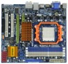
CPU Chipset Memory Expansion Slot Graphics Audio LAN Rear Panel I/O - Micro ATX Form Factor: 9.6-in x 8.6-in, 24.4 cm x 21.8 cm - Solid Capacitor for CPU power - Support for Socket AM3 processors: AMD PhenomTM II X4 / X3 / X2 (except 920 / 940) and Athlon II X4 / X3 / X2 processors - Supports AMD - ASRock M3A785GMH/128M | User Manual - Page 7
ACPI 1.1 Compliance Wake Up Events - Supports jumperfree - SMBIOS 2.3.1 Support - VCCM, NB Voltage Multi-adjustment - Supports Smart BIOS - Drivers, Utilities, AntiVirus Software (Trial Version), AMD OverDriveTM Utility, AMD Live! Explorer, AMD Fusion - ASRock OC Tuner (see CAUTION 10) - Intelligent - ASRock M3A785GMH/128M | User Manual - Page 8
installation. 3. Whether 1600MHz memory speed is supported depends on the AM3 CPU you adopt. If you want to adopt DDR3 1600 memory module on this motherboard, please refer to the memory support list on our website for the compatible memory modules. ASRock website http://www.asrock.com 4. Due to the - ASRock M3A785GMH/128M | User Manual - Page 9
of Intelligent Energy Saver. ASRock website: http://www.asrock.com 12. ASRock Instant Flash is a BIOS flash utility embedded in Flash ROM. This convenient BIOS update tool allows you to update system BIOS without entering operating systems first like MS-DOS or Windows®. With this utility, you - ASRock M3A785GMH/128M | User Manual - Page 10
the completed system shall be under 1.00W in off mode condition. To meet EuP standard, an EuP ready motherboard and an EuP ready power supply are required. According to Intel's suggestion, the EuP ready power supply must recommend you checking with the power supply manufacturer for more details. 10 - ASRock M3A785GMH/128M | User Manual - Page 11
DVD playback is only supported under Windows® VistaTM / VistaTM 64-bit OS. If you install Windows® XP / XP 64-bit OS, the function of 1080p Blu-ray (BD) / HD-DVD playback is not available, please visit our website for AMD 785G VGA driver update in the future. ASRock website http://www.asrock.com 11 - ASRock M3A785GMH/128M | User Manual - Page 12
264. * Above passed films are tested under below configuration. Items Configurations CPU AM3 all series CPU VGA Onboard VGA with DVI-D port Memory Single Channel DDR3 1066, 1GB x 1 OS Windows® VistaTM or Windows® VistaTM 64 Playback Software CyberLink PowerDVD Ultra (Version 7.3 or above - ASRock M3A785GMH/128M | User Manual - Page 13
Bottom: Center: Top: SIDE SPK USB 2.0 T: USB0 Top: B: USB1 RJ-45 CPU_FAN1 M3A785GMH/128M IDE1 RoHS REAR SPK FRONT Top: LINE IN Center: Bottom: LAN Super I/O IR1 1 AUDIO CODEC HD_AUDIO1 1 CD1 PCIE1 RoHS AMD 785G Chipset CLRCMOS1 1 PCIE2 Sideport memory 128M PCI Express 2.0 PCI1 - ASRock M3A785GMH/128M | User Manual - Page 14
11 10 9 8 9 10 11 *** 12 13 14 Microphone (Pink) Optical SPDIF Out Port USB 2.0 Ports (USB01) Powered eSATAII/USB Connector HDMI Port VGA/DVI-D Port PS/2 Keyboard Port (Purple) * There are two LED next to the LAN port. Please refer to the table below for the LAN port LED indications. LAN Port - ASRock M3A785GMH/128M | User Manual - Page 15
2. Installation This is a Micro ATX form factor (9.6-in x 8.6-in, 24.4 cm x 21.8 cm) motherboard. Before you install the motherboard, study the configuration of your chassis to ensure that the motherboard fits into it. Pre-installation Precautions Take note of the following precautions before you - ASRock M3A785GMH/128M | User Manual - Page 16
. Make sure that the CPU and the heatsink are securely fastened and in good contact with each other. Then connect the CPU fan to the CPU FAN connector (CPU_FAN1, see Page 13, No. 3). For proper installation, please kindly refer to the instruction manuals of the CPU fan and the heatsink. 16 - ASRock M3A785GMH/128M | User Manual - Page 17
2.3 Installation of Memory Modules (DIMM) This motherboard provides four 240-pin DDR3 (Double Data Rate 3) DIMM slots, and supports Dual Channel Memory Technology. For dual channel configuration, you always need to install identical (the same brand, speed, size and chip-type) DDR3 DIMM pair in the - ASRock M3A785GMH/128M | User Manual - Page 18
matches the break on the slot. notch break notch break The DIMM only fits in one correct orientation. It will cause permanent damage to the motherboard and the DIMM if you force the DIMM into the slot at incorrect orientation. Step 3. Firmly insert the DIMM into the slot until the retaining - ASRock M3A785GMH/128M | User Manual - Page 19
Slots) There are 2 PCI slots and 2 PCI Express slots on this motherboard. PCI slots: PCI slots are used to install expansion cards that have ; Green) is used for PCI Express cards with x1 lane width cards, such as Gigabit LAN card, SATA2 card, etc. PCIE2 (PCIE x16 slot; Green) is used for PCI Express - ASRock M3A785GMH/128M | User Manual - Page 20
motherboard. This motherboard also provides independent display controllers for DVI-D, D-Sub or HDMI to support dual VGA output so that DVI-D, D-sub or HDMI for dual monitor output support: DVI-D + D-Sub or HDMI + D-Sub. 2. If you have installed onboard VGA driver from our support CD to your system - ASRock M3A785GMH/128M | User Manual - Page 21
is less than the total capability of the system memory. If you do not adjust the BIOS setup, the default value of "Share Memory", [Auto], will disable VGA/D-Sub function when the add-on VGA card is inserted to this motherboard. 4. Install the onboard VGA driver and the add-on PCI Express VGA card - ASRock M3A785GMH/128M | User Manual - Page 22
. For Windows® VistaTM supported on this motherboard. To use HDCP function with this motherboard, you need to adopt the monitor that supports HDCP function as well. Therefore, you can enjoy the superior display quality with high-definition HDCP encryption contents. Please refer to below instruction - ASRock M3A785GMH/128M | User Manual - Page 23
3450 series graphics processor and a motherboard based on an AMD 785G integrated chipset, all operating in a Windows® VistaTM environment. Please refer to below PCI Express graphics card support list for ATITM Hybrid CrossFireXTM. For the future update of more compatible PCI Express graphics - ASRock M3A785GMH/128M | User Manual - Page 24
8. Click "Yes" to continue. Step 9. Click "OK" to save your change. Step 10. Reboot your system. Then you can freely enjoy the benefit of HybridTM CrossFireXTM feature. * Hybrid * For further information of ATITM Hybrid CrossFireXTM technology, please check AMD website for up dates and details. 24 - ASRock M3A785GMH/128M | User Manual - Page 25
see p.13, No. 1) +5V +5VSB +5VSB (standby) for PS/2 or USB wake up events. Note: To select +5VSB, it requires 2 Amp and higher standby current not clear the CMOS right after you update the BIOS. If you need to clear the CMOS when you just finish updating the BIOS, you must boot up the system - ASRock M3A785GMH/128M | User Manual - Page 26
blue end connect the black end to the motherboard to the IDE devices 80-conductor ATA 66/100/133 cable Note: Please refer to the instruction of your IDE device vendor for the details. Serial ATAII Connectors (SATAII_1 (PORT 0): see p.13, No. 20) (SATAII_2 (PORT 1): see p.13, No. 19) (SATAII_3 - ASRock M3A785GMH/128M | User Manual - Page 27
the power connector of the power supply. Besides four default USB 2.0 ports on the I/O panel, there are three USB 2.0 headers on this motherboard. Each USB 2.0 header can support two USB 2.0 ports. This header supports an optional wireless transmitting and receiving infrared module. This connector - ASRock M3A785GMH/128M | User Manual - Page 28
the chassis must support HDA to function correctly. Please follow the instruction in our manual and chassis manual to install your BIOS Setup Utility. Enter Advanced Settings, and then select Chipset Configuration. Set the Front Panel Control option from [Auto] to [Enabled]. F. Enter Windows - ASRock M3A785GMH/128M | User Manual - Page 29
fan (Quiet Fan) support, the 3-Pin CPU fan still can work successfully even without the fan speed control function. If you plan to connect the 3-Pin CPU fan to the CPU fan connector on this motherboard, please connect it to Pin 1-3. Pin 1-3 Connected 3-Pin Fan Installation ATX Power Connector (24 - ASRock M3A785GMH/128M | User Manual - Page 30
guide. Some default setting of SATAII hard disks may not be at SATAII mode, which operate with the best performance. In order to enable SATAII function, please follow the below instruction 's website for details: http://www.hitachigst.com/hdd/support/download.htm The above examples are just for your - ASRock M3A785GMH/128M | User Manual - Page 31
This motherboard adopts AMD SB710 south bridge chipset that supports Serial ATA (SATA) / Serial ATAII (SATAII) hard disks and RAID (RAID 0, RAID 1, RAID 10 and JBOD) functions. You may install SATA / SATAII hard disks on this motherboard for internal storage devices. This section will guide you - ASRock M3A785GMH/128M | User Manual - Page 32
is installed into system properly. The latest SATA / SATAII driver is available on our support website: www.asrock.com 4. Make sure to use the SATA power cable & data cable, which are from our motherboard package. 5. Please follow below instructions step by step to reduce the risk of HDD crash or - ASRock M3A785GMH/128M | User Manual - Page 33
Hot Plug: Please do follow below instruction sequence to process the Hot Plug, ) to the power supply 1x4-pin cable. the motherboard's SATAII connector. SATA power cable 1x4-pin power process the Hot Unplug: Please do follow below instruction sequence to process the Hot Unplug, improper procedure - ASRock M3A785GMH/128M | User Manual - Page 34
Mode" option to [RAID]. STEP 2: Make a SATA / SATAII Driver Diskette. A. Insert the ASRock Support CD into your optical drive to boot your system. (There are two ASRock Support CD in the motherboard gift box pack, please choose the one for Windows® XP / XP 64-bit.) B. During POST at the - ASRock M3A785GMH/128M | User Manual - Page 35
install Windows? " page, please insert the ASRock Support CD into your optical drive, and click the "Load Driver" button on the left on the bottom to load the AMD RAID drivers. AMD RAID drivers are in the following path in our Support CD: (There are two ASRock Support CD in the motherboard gift - ASRock M3A785GMH/128M | User Manual - Page 36
set up "SATA Operation Mode" to [RAID] in BIOS first. Then, please set the RAID configuration by using the Windows RAID installation guide in the following path in the Support CD: .. \ RAID Installation Guide NOTE2. Currently, if you install Windows® VistaTM / Windows® VistaTM 64-bit on IDE HDDs and - ASRock M3A785GMH/128M | User Manual - Page 37
install Windows? " page, please insert the ASRock Support CD into your optical drive, and click the "Load Driver" button on the left on the bottom to load the AMD AHCI drivers. AMD AHCI drivers are in the following path in our Support CD: (There are two ASRock Support CD in the motherboard gift - ASRock M3A785GMH/128M | User Manual - Page 38
This motherboard supports Untied Overclocking Technology, which means during overclocking, FSB enjoys better margin due to fixed PCI / PCIE buses. Before you enable Untied Overclocking function, please enter "Overclock Mode" option of BIOS setup to set the selection from [Auto] to [CPU, PCIE - ASRock M3A785GMH/128M | User Manual - Page 39
BIOS SETUP UTILITY to configure your system. The SPI Memory on the motherboard stores the BIOS SETUP UTILITY. You may run the BIOS Because the BIOS software is constantly being updated, the following BIOS setup screens set up overclocking features Advanced To set up the advanced BIOS features H/W - ASRock M3A785GMH/128M | User Manual - Page 40
09] [Fri 06/26/2009] BIOS Version : M3A785GMH/128M P1.0 Processor Type : AMD Phenom(tm) II X3 720 Processor (64bit) Processor Speed : 2800MHz Microcode Update : 100F42/1000086 L1 Cache Size : 384KB L2 Cache Size : 1536KB L3 Cache Size : 6144KB Total Memory DDR3_A1 DDR3_B1 DDR3_A2 DDR3_B2 : 2048MB - ASRock M3A785GMH/128M | User Manual - Page 41
overclocking features. BIOS SETUP UTILITY Main OC Tweaker Advanced H/W Monitor Boot Security Exit EZ Overclocking Load Optimized CPU OC Setting [Press Enter] CPU Configuration Overclock Mode CPU [Auto] CPU Thermal Throttle [Auto] Overclocking may cause damage to your CPU and motherboard. It - ASRock M3A785GMH/128M | User Manual - Page 42
1800 MHz Processor Maximum Voltage 1.2500 V Multiplier/Voltage Change [Manual] CPU Frequency Multiplier [x0.5 100 MHz] CPU Voltage [0.6000 V] NB Frequency Multiplier [x5.0 1000 MHz] Overclocking may cause damage to your CPU and motherboard. It should be done at your own risk and expense - ASRock M3A785GMH/128M | User Manual - Page 43
default value is [Auto]. DRAM Timing BIOS SETUP UTILITY OC Tweaker DRAM Timing Memory Controller Mode Power Down Enable Bank Interleaving This option appears only when you adopt Phenom CPU. It allows you to enable Channel Memory Interleaving. Configuration options: [Disabled], [XOR of - ASRock M3A785GMH/128M | User Manual - Page 44
CAS Latency (CL) Use this item to adjust the means of memory accessing. Configuration options: [Auto], [4CLK] to [12CLK]. The default value is [Auto]. TRCD Use this to adjust TRCD values. Configuration options: [Auto], [5CLK] to [12CLK]. - ASRock M3A785GMH/128M | User Manual - Page 45
TRFC0 Use this to adjust TRFC0 values. Configuration options: [Auto], [90ns], [110ns], [160ns], [300ns] and [350ns]. The default value is [Auto]. TRFC1 Use this to adjust TRFC1 values. Configuration options: [Auto], [90ns], [110ns], [160ns], [300ns] and [350ns]. The default value is [Auto]. MA - ASRock M3A785GMH/128M | User Manual - Page 46
CHA CS/ODT Drive Strength Use this to adjust values for CHA CS/ODT Drive Strength. Configuration options: [Auto], [1.00x], [1.25x], [1.50x] and [2.00x]. The default value is [Auto]. CHA ODDR/CMD Drive Strength Use this to adjust values for CHA ODDR/CMD Drive Strength. Configuration options: [Auto], - ASRock M3A785GMH/128M | User Manual - Page 47
MHz], [533 MHz], [667 MHz], [800 MHz], [1066 MHz] and [1333 MHz]. This option only appears when you set "Internal Graphics Mode" to [SIDEPORT] or [UMA+SIDEPORT]. Onboard GPU Clock Override This allows you to enable or disable the Onboard GPU Clock Override feature. Onboard GPU Clock This option only - ASRock M3A785GMH/128M | User Manual - Page 48
section may cause the system to malfunction. ASRock Instant Flash ASRock Instant Flash is a BIOS flash utility embedded in Flash ROM. This convenient BIOS update tool allows you to update system BIOS without entering operating systems first like MS-DOS or Windows®. Just launch this tool and save - ASRock M3A785GMH/128M | User Manual - Page 49
AMD's Cool 'n' QuietTM technology. The default value is [Auto]. Configuration options: [Auto], [Enabled] and [Disabled]. If you install Windows® VistaTM and want to enable this function, please set this item to [Enabled]. Please note that enabling this function may reduce CPU voltage and memory - ASRock M3A785GMH/128M | User Manual - Page 50
3.4.2 Chipset Configuration BIOS SETUP UTILITY Advanced Chipset Settings Onboard HD Audio Front Panel CD-In OnBoard Lan Primary Graphics Adapter Internal Graphics Mode Share Memory Onboard HDMI HD Audio Surround View [Auto] [Enabled] [Enabled] [Enabled] [PCI] [UMA+SIDEPORT] [Auto] [Disabled] [ - ASRock M3A785GMH/128M | User Manual - Page 51
Onboard HDMI HD Audio This allows you to enable or disable the onboard HDMI HD Audio in AMD 785G. Surround View This allows you to enable or disable the Surround View feature or Hybrid CrossFireXTM feature. 51 - ASRock M3A785GMH/128M | User Manual - Page 52
3.4.3 ACPI Configuration BIOS SETUP UTILITY Advanced ACPI Settings Suspend To RAM Away Mode Support Restore on AC / Power Loss or disable the feature Check Ready Bit. Away Mode Support Use this item to enable or disable Away Mode support under Windows® XP Media Center OS. The default value is [ - ASRock M3A785GMH/128M | User Manual - Page 53
plan to use this motherboard to submit Windows® VistaTM certification. 3.4.4 Storage Configuration BIOS SETUP UTILITY Advanced Storage as the example in the following instruction, which can be applied to the configurations of "IDE1 Slave" as well. BIOS SETUP UTILITY Advanced IDE Master Device - ASRock M3A785GMH/128M | User Manual - Page 54
automatically detect the hard disk drive. After selecting the hard disk information into BIOS, use a disk utility, such as FDISK, to partition and format the item to select the LBA/Large mode for a hard disk > 512 MB under DOS and Windows; for Netware and UNIX user, select [Disabled] to disable the - ASRock M3A785GMH/128M | User Manual - Page 55
3.4.5 PCIPnP Configuration BIOS SETUP UTILITY Advanced Advanced PCI / PnP Settings PCI Latency Timer PCI IDE BusMaster [32] [Enabled] Value in units of PCI clocks for PCI device latency - ASRock M3A785GMH/128M | User Manual - Page 56
configure the type of your floppy drive. BIOS SETUP UTILITY Advanced Floppy Configuration Floppy A [1.44 MB 312"] Select the type of floppy drive Floppy Controller Serial Port Address Infrared Port Address PS/2 Port Type [Enabled] [3F8 / IRQ4] [Disabled] [Auto] Allow BIOS to Enable or - ASRock M3A785GMH/128M | User Manual - Page 57
Use this item to enable or disable the USB 2.0 support. Legacy USB Support Use this option to select legacy support for USB devices. There are four configuration options: [Enabled], [Auto], [Disabled] and [BIOS Setup Only]. The default value is [Enabled]. Please refer to below descriptions for - ASRock M3A785GMH/128M | User Manual - Page 58
to monitor the status of the hardware on your system, including the parameters of the CPU temperature, motherboard temperature, CPU fan speed, chassis fan speed, and the critical voltage. BIOS SETUP UTILITY Main OC Tweaker Advanced H/W Monitor Boot Security Exit Hardware Health Event Monitoring - ASRock M3A785GMH/128M | User Manual - Page 59
for you to configure the boot settings and the boot priority. BIOS SETUP UTILITY Main OC Tweaker Advanced H/W Monitor Boot Security Exit Boot Settings Configuration Full Screen Logo AddOn ROM Display Boot Logo Boot From Onboard LAN Bootup Num-Lock [Enabled] [Enabled] [Auto] [Disabled] [On] - ASRock M3A785GMH/128M | User Manual - Page 60
Screen Logo". Configuration options: [Auto], [PCIE2.0 Revolution], [Scenery] and [ASRock]. The default value is [Auto]. Currently, the option [Auto] is set to Aircraft. Boot From Onboard LAN Use this item to enable or disable the Boot From Onboard LAN feature. Boot Up Num-Lock If this item is set to - ASRock M3A785GMH/128M | User Manual - Page 61
. Discard Changes When you select this option, it will pop-out the following message, "Discard changes?" Select [OK] to discard all changes. Load BIOS Defaults Load BIOS default values for all the setup questions. F9 key can be used for this operation. Load Performance Setup Default (IDE/SATA) This - ASRock M3A785GMH/128M | User Manual - Page 62
install the necessary drivers to activate the devices. 4.2.3 Utilities Menu The Utilities Menu shows the applications software that the motherboard supports. Click on a specific item then follow the installation wizard to install it. 4.2.4 Contact Information If you need to contact ASRock or want to
-
 1
1 -
 2
2 -
 3
3 -
 4
4 -
 5
5 -
 6
6 -
 7
7 -
8
-
9
-
10
-
11
-
12
-
13
-
14
-
15
-
16
-
17
-
18
-
19
-
20
-
21
-
22
-
23
-
24
-
25
-
26
-
27
-
28
-
29
-
30
-
31
-
32
-
33
-
34
-
35
-
36
-
37
-
38
-
39
-
40
-
41
-
42
-
43
-
44
-
45
-
46
-
47
-
48
-
49
-
50
-
51
-
52
-
53
-
54
-
55
-
56
-
57
-
58
-
59
-
60
-
61
-
62
 |
 |

1
M3A785GMH/128M
User Manual
Version 1.0
Published July 2009
Copyright©2009 ASRock INC. All rights reserved.