ASRock M3A790GMH/128M User Manual
ASRock M3A790GMH/128M Manual
 |
View all ASRock M3A790GMH/128M manuals
Add to My Manuals
Save this manual to your list of manuals |
ASRock M3A790GMH/128M manual content summary:
- ASRock M3A790GMH/128M | User Manual - Page 1
M3A790GMH/128M User Manual Version 1.0 Published July 2009 Copyright©2009 ASRock INC. All rights reserved. 1 - ASRock M3A790GMH/128M | User Manual - Page 2
purchaser for backup purpose, without written consent of ASRock Inc. Products and corporate names appearing in this manual may or may not be registered trademarks or copyrights USA ONLY The Lithium battery adopted on this motherboard contains Perchlorate, a toxic substance controlled in Perchlorate - ASRock M3A790GMH/128M | User Manual - Page 3
HD-DVD Playback Support 11 1.4 1080p Blu-ray (BD) / HD-DVD Films Which Pass Our Lab Test 12 1.5 Motherboard Layout 13 Guide ..... 33 2.13 Driver Installation Guide 35 2.14 Installing Windows® XP / XP 64-bit / VistaTM / VistaTM 64-bit With RAID Functions 35 2.14.1 Installing Windows® XP / XP 64 - ASRock M3A790GMH/128M | User Manual - Page 4
UTILITY 40 3.1 Introduction 40 3.1.1 BIOS Menu Bar 40 3.1.2 Navigation Keys 41 3.2 Main Screen 41 3.3 Smart Exit Screen 62 4 . Software Support 63 4.1 Install Operating System 63 4.2 Support CD Information 63 4.2.1 Running Support CD 63 4.2.2 Drivers Menu 63 4.2.3 Utilities Menu 63 - ASRock M3A790GMH/128M | User Manual - Page 5
about the model you are using. www.asrock.com/support/index.asp 1.1 Package Contents 1 x ASRock M3A790GMH/128M Motherboard (Micro ATX Form Factor: 9.6-in x 8.6-in, 24.4 cm x 21.8 cm) 1 x ASRock M3A790GMH/128M Quick Installation Guide 2 x ASRock M3A790GMH/128M Support CD 1 x Ultra ATA 66/100/133 IDE - ASRock M3A790GMH/128M | User Manual - Page 6
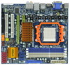
24.4 cm x 21.8 cm - Solid Capacitor for CPU power - Support for Socket AM3 processors: AMD PhenomTM II X4 / X3 / X2 (except 920 / 940 - Built-in 128MB DDR3 1333(OC)/1200MHz SidePort Memory - Three VGA Output options: D-Sub, DVI-D and HDMI - Supports HDCP function - Supports Full HD 1080p Blu - ASRock M3A790GMH/128M | User Manual - Page 7
ACPI 1.1 Compliance Wake Up Events - Supports jumperfree - SMBIOS 2.3.1 Support - VCCM, NB Voltage Multi-adjustment - Supports Smart BIOS - Drivers, Utilities, AntiVirus Software (Trial Version), AMD OverDriveTM Utility, AMD Live! Explorer, AMD Fusion - ASRock OC Tuner (see CAUTION 10) - Intelligent - ASRock M3A790GMH/128M | User Manual - Page 8
Center / XP 64-bit / VistaTM / VistaTM 64-bit compliant supported depends on the AM3 CPU you adopt. If you want to adopt DDR3 1600 memory module on this motherboard, please refer to the memory support list on our website for the compatible memory modules. ASRock website http://www.asrock - ASRock M3A790GMH/128M | User Manual - Page 9
mono modes. For audio output, this motherboard supports 2-channel, 4-channel, 6-channel, and 8-channel modes. Please check the table on page 13 for proper connection. 8. Before installing SATAII hard disk to SATAII connector, please read the "SATAII Hard Disk Setup Guide" on page 31 to adjust your - ASRock M3A790GMH/128M | User Manual - Page 10
to EuP, the total AC power of the completed system shall be under 1.00W in off mode condition. To meet EuP standard, an EuP ready motherboard and an EuP ready power supply are required. According to Intel's suggestion, the EuP ready power supply must meet the standard of 5v standby power - ASRock M3A790GMH/128M | User Manual - Page 11
playback is only supported under Windows® VistaTM / VistaTM 64-bit OS. If you install Windows® XP / XP 64-bit OS, the function of 1080p Blu-ray (BD) / HD-DVD playback is not available, please visit our website for AMD 790GX VGA driver update in the future. ASRock website http://www.asrock.com 11 - ASRock M3A790GMH/128M | User Manual - Page 12
BD) / HD-DVD Films in Our Lab Test DVD Film Name Format Type Blu-ray SWORDFISH VC-1 DVD tested under below configuration. Items Configurations CPU AM3 all series CPU VGA Onboard VGA with DVI-D port Memory Single Channel DDR3 1066, 1GB x 1 OS Windows® VistaTM or Windows® VistaTM 64 - ASRock M3A790GMH/128M | User Manual - Page 13
, 240-pin module) DDR3_A1 (64 bit, 240-FpinSBmo8d0ul0e) AM3 Phenom II HT3.0 DDR3 1600 EUP Ready SOCKET AM3 HDMI1 IEEE 1394 eSATAII 34 33 32 31 30 29 Optical SPDIF MIC IN Bottom: Center: Top: SIDE SPK USB 2.0 T: USB0 Top: B: USB1 RJ-45 CPU_FAN1 M3A790GMH/128M IDE1 RoHS REAR SPK FRONT - ASRock M3A790GMH/128M | User Manual - Page 14
No. 6) (No. 5) (No. 7) 2 V -- -- -- 4 V V -- -- 6 V V V -- 8 V V V V *** To support AC3 audio format with HDMI Audio under VistaTM, please install the HDMI audio driver in XP support CD AAX790M-10. The driver is located under the path: ..\Drivers\NB Audio\REALTEK\XP64_XP(R1.68 - ASRock M3A790GMH/128M | User Manual - Page 15
the power is switched off or the power cord is detached from the power supply. Failure to do so may cause severe damage to the motherboard, peripherals, and/or components. 1. Unplug the power cord from the wall socket before touching any component. 2. To avoid damaging the - ASRock M3A790GMH/128M | User Manual - Page 16
Socket Lever 2.2 Installation of CPU Fan and Heatsink After you install the CPU into this motherboard, it is necessary to install a larger heatsink and cooling fan to dissipate heat. You 3). For proper installation, please kindly refer to the instruction manuals of the CPU fan and the heatsink. 16 - ASRock M3A790GMH/128M | User Manual - Page 17
of Memory Modules (DIMM) This motherboard provides four 240-pin DDR3 (Double Data Rate 3) DIMM slots, and supports Dual Channel Memory Technology. For dual channel configuration, you always need to install identical (the same brand, speed, size and chip-type) DDR3 DIMM pair in the slots of - ASRock M3A790GMH/128M | User Manual - Page 18
matches the break on the slot. notch break notch break The DIMM only fits in one correct orientation. It will cause permanent damage to the motherboard and the DIMM if you force the DIMM into the slot at incorrect orientation. Step 3. Firmly insert the DIMM into the slot until the retaining - ASRock M3A790GMH/128M | User Manual - Page 19
2.4 Expansion Slots (PCI and PCI Express Slots) There are 2 PCI slots and 2 PCI Express slots on this motherboard. PCI slots: PCI slots are used to install expansion cards that have the 32-bit PCI interface. PCIE slots: PCIE1 (PCIE x1 slot; Green) is - ASRock M3A790GMH/128M | User Manual - Page 20
after your system boots. If you haven't installed onboard VGA driver yet, please install onboard VGA driver from our support CD to your system and restart your computer. Then you can start to use multi monitor function on this motherboard. When you playback HDCP-protected video from Blu-ray (BD - ASRock M3A790GMH/128M | User Manual - Page 21
memory. If you do not adjust the BIOS setup, the default value of "Share Memory", [Auto], will disable VGA/D-Sub function when the add-on VGA card is inserted to this motherboard. 4. Install the onboard VGA driver and the add-on PCI Express VGA card driver to your system. If you have installed - ASRock M3A790GMH/128M | User Manual - Page 22
/ VistaTM 64-bit OS: supported on this motherboard. To use HDCP function with this motherboard, you need to adopt the monitor that supports HDCP function as well. Therefore, you can enjoy the superior display quality with high-definition HDCP encryption contents. Please refer to below instruction - ASRock M3A790GMH/128M | User Manual - Page 23
2 . 6 ATITM Hybrid CrossFireXTM Operation Guide This motherboard supports ATITM Hybrid CrossFireXTM feature. ATITM Hybrid CrossFireXTM brings multi-GPU performance capabilities by enabling an AMD 790GX integrated graphics processor and a discrete graphics processor to operate simultaneously with - ASRock M3A790GMH/128M | User Manual - Page 24
Step 7. Double-click "ATI Catalyst Control Center". Click "View", click "CrossFireTM", and then select the option "Enable CrossFireTM". View CrossFireTM Enable CrossFireTM Step 8. Click "Yes" to continue. Step 9. Click "OK" to save your change. Step 10. Reboot your system. Then you can freely - ASRock M3A790GMH/128M | User Manual - Page 25
and pin3 on CLRCMOS1 for 5 seconds. However, please do not clear the CMOS right after you update the BIOS. If you need to clear the CMOS when you just finish updating the BIOS, you must boot up the system first, and then shut it down before you do the clear-CMOS action - ASRock M3A790GMH/128M | User Manual - Page 26
black end to the motherboard to the IDE devices 80-conductor ATA 66/100/133 cable Note: Please refer to the instruction of your IDE device vendor 3) SATAII_5 (PORT 4) These five Serial ATAII (SATAII) connectors support SATAII or SATA hard disk for internal storage devices. The current SATAII - ASRock M3A790GMH/128M | User Manual - Page 27
supply. Besides four default USB 2.0 ports on the I/O panel, there are three USB 2.0 headers on this motherboard. Each USB 2.0 header can support two USB 2.0 ports. This header supports an optional wireless transmitting and receiving infrared module. This connector allows you to receive stereo audio - ASRock M3A790GMH/128M | User Manual - Page 28
support HDA to function correctly. Please follow the instruction in our manual and chassis manual to for AC'97 audio panel. E. Enter BIOS Setup Utility. Enter Advanced Settings, and then To activate the front mic. For Windows® XP / XP 64-bit OS: Please select "Front Mic" as default record device - ASRock M3A790GMH/128M | User Manual - Page 29
2 GND 1 Please connect the CPU fan cable to this connector and match the black wire to the ground pin. Though this motherboard provides 4-Pin CPU fan (Quiet Fan) support, the 3-Pin CPU fan still can work successfully even without the fan speed control function. If you plan to connect the 3-Pin - ASRock M3A790GMH/128M | User Manual - Page 30
IEEE 1394 Header (9-pin FRONT_1394) (see p.13 No. 23) RXTPAM_0 GND RXTPBM_0 +12V GND 1 +12V RXTPBP_0 GND RXTPAP_0 Besides one default IEEE 1394 port on the I/O panel, there is one IEEE 1394 header (FRONT_1394) on this motherboard. This IEEE 1394 header can support one IEEE 1394 port. 30 - ASRock M3A790GMH/128M | User Manual - Page 31
guide. Some default setting of SATAII hard disks may not be at SATAII mode, which operate with the best performance. In order to enable SATAII function, please follow the below instruction 's website for details: http://www.hitachigst.com/hdd/support/download.htm The above examples are just for your - ASRock M3A790GMH/128M | User Manual - Page 32
AMD SB750 south bridge chipset that supports Serial ATA (SATA) / Serial ATAII (SATAII) hard disks and RAID (RAID 0, RAID 1, RAID 5, RAID 10 and JBOD) functions. You may install SATA / SATAII hard disks on this motherboard for internal storage devices. This section will guide you to install the SATA - ASRock M3A790GMH/128M | User Manual - Page 33
is installed into system properly. The latest SATA / SATAII driver is available on our support website: www.asrock.com 4. Make sure to use the SATA power cable & data cable, which are from our motherboard package. 5. Please follow below instructions step by step to reduce the risk of HDD crash or - ASRock M3A790GMH/128M | User Manual - Page 34
cable to (White) to the power supply 1x4-pin cable. the motherboard's SATAII connector. SATA power cable 1x4-pin power connector (White) Step attention, before you process the Hot Unplug: Please do follow below instruction sequence to process the Hot Unplug, improper procedure will cause the SATA - ASRock M3A790GMH/128M | User Manual - Page 35
to [RAID]. STEP 2: Make a SATA / SATAII Driver Diskette. A. Insert the ASRock Support CD into your optical drive to boot your system. (There are two ASRock Support CD in the motherboard gift box pack, please choose the one for Windows® XP / XP 64-bit.) B. During POST at the beginning of - ASRock M3A790GMH/128M | User Manual - Page 36
the left on the bottom to load the AMD RAID drivers. AMD RAID drivers are in the following path in our Support CD: (There are two ASRock Support CD in the motherboard gift box pack, please choose the one for Windows® VistaTM / VistaTM 64-bit.) .. \ I386 (For Windows® VistaTM OS) .. \ AMD64 (For - ASRock M3A790GMH/128M | User Manual - Page 37
"SATA Operation Mode" to [RAID] in BIOS first. Then, please set the RAID configuration by using the Windows RAID installation guide in the following path in the Support CD: .. \ RAID Installation Guide NOTE2. Currently, if you install Windows® VistaTM / Windows® VistaTM 64-bit on IDE HDDs and there - ASRock M3A790GMH/128M | User Manual - Page 38
the left on the bottom to load the AMD AHCI drivers. AMD AHCI drivers are in the following path in our Support CD: (There are two ASRock Support CD in the motherboard gift box pack, please choose the one for Windows® VistaTM / VistaTM 64-bit.) .. \ I386 (For Windows® VistaTM OS) .. \ AMD64 (For - ASRock M3A790GMH/128M | User Manual - Page 39
16 Untied Overclocking Technology This motherboard supports Untied Overclocking Technology, which means during overclocking, FSB enjoys better margin due to fixed PCI / PCIE buses. Before you enable Untied Overclocking function, please enter "Overclock Mode" option of BIOS setup to set the selection - ASRock M3A790GMH/128M | User Manual - Page 40
to configure your system. The SPI Memory on the motherboard stores the BIOS SETUP UTILITY. You may run the BIOS SETUP UTILITY when you start up the computer. Please press or during the Power-On-Self-Test (POST) to enter the BIOS SETUP UTILITY, otherwise, POST will continue with its - ASRock M3A790GMH/128M | User Manual - Page 41
Time System Date [17:00:09] [Fri 06/26/2009] BIOS Version : M3A790GMH/128M P1.0 Processor Type : AMD Phenom(tm) II X3 720 Processor DDR3_B2 : 2048MB Single-Channel Memory Mode : None : None : None : 2048MB/667MHz (DDR3 1333) Security Exit Use [Enter], [TAB] or [SHIFT-TAB] to select a field. - ASRock M3A790GMH/128M | User Manual - Page 42
Load Performance Setup Default (IDE/SATA) Load Performance Setup AHCI Mode Load Performance Setup RAID Mode Load Power Saving Setup Default BIOS Update Utility ASRock Instant Flash EZ Overclocking Load Optimized CPU OC Setting [Press Enter] Exit system setup after saving the changes. F10 key can - ASRock M3A790GMH/128M | User Manual - Page 43
must use FAT32/16/ 12 file system. If you execute ASRock Instant Flash utility, the utility will show the BIOS files and their respective information. Select the proper BIOS file to update your BIOS, and reboot your system after BIOS update process completes. Load Optimized CPU OC Setting You can - ASRock M3A790GMH/128M | User Manual - Page 44
Copyright 1985-2005, American Megatrends, Inc. Setting wrong values in this section may cause the system to malfunction. 3.4.1 CPU Configuration BIOS SETUP UTILITY Advanced CPU Configuration Overclock Mode [Auto] CPU Frequency (MHz) [200] PCIE Frequency (MHz) Spread Spectrum Boot Failure - ASRock M3A790GMH/128M | User Manual - Page 45
]. Configuration options: [Enabled] and [Disabled]. Enhance Halt State All processors support the Halt State (C1). The C1 state is supported through the native processor instructions HLT and MWAIT and requires no hardware support from the chipset. In the C1 power state, the processor maintains the - ASRock M3A790GMH/128M | User Manual - Page 46
is set to [Auto] by default. If it is set to [Manual], you may adjust the value of Processor Frequency and Processor Voltage. However, it is recommended to keep the default value for system stability. BIOS SETUP UTILITY Advanced CPU Configuration Overclock Mode CPU Frequency (MHz) PCIE Frequency - ASRock M3A790GMH/128M | User Manual - Page 47
3.4.2 Memory Configuration BIOS SETUP UTILITY Advanced Memory Configuration Memory Clock Memory can set one of the standard values as listed: [400 MHz (DDR3 800)], [533 MHz (DDR3 1066)], [667 MHz (DDR3 1333)] and [800MHz (DDR3 1600)]. Memory Controller Mode It allows you to adjust the memory - ASRock M3A790GMH/128M | User Manual - Page 48
TRAS Use this to adjust TRAS values. Configuration options: [Auto], [15CLK] to [30CLK]. The default value is [Auto]. TRTP Use this to adjust TRTP values. Configuration options: [Auto], [4CLK] to [7CLK]. The default value is [Auto]. TRRD Use this to adjust TRRD values. Configuration options: [Auto], - ASRock M3A790GMH/128M | User Manual - Page 49
CHA Addr/Cmd Fine Delay Use this to adjust values for CHA Addr/Cmd Fine Delay feature. Configuration options: [Auto], [No Delay], [1/64CLK] to [31/64CLK]. The default value is [Auto]. CHA Addr/Cmd Setup Time Use this to adjust values for CHA Addr/Cmd Setup Time feature. Configuration options: [Auto - ASRock M3A790GMH/128M | User Manual - Page 50
CHA DATA Drive Strength Use this to adjust values for CHA DATA Drive Strength. Configuration options: [Auto], [0.75x], [1.00x], [1.25x] and [1.50x]. The default value is [Auto]. CHA DQS Drive Strength Use this to adjust values for CHA DQS Drive Strength. Configuration options: [Auto], [0.75x], [1. - ASRock M3A790GMH/128M | User Manual - Page 51
BIOS OnBoard HD Audio. If you plan to use this motherboard to submit Windows® VistaTM logo test, please disable this option. OnBoard Lan This allows default value is [Auto]. Configuration options: [Auto], [32MB], [64MB], [128MB], [256MB] and [512MB]. This option only appears when you set "Internal - ASRock M3A790GMH/128M | User Manual - Page 52
Graphics Mode" to [SIDEPORT] or [UMA+SIDEPORT]. Onboard HDMI HD Audio This allows you to enable or disable the onboard HDMI HD Audio in AMD 790GX. Onboard GPU Clock Override This allows you to enable or disable the Onboard GPU Clock Override feature. Onboard GPU Clock This option only appears when - ASRock M3A790GMH/128M | User Manual - Page 53
3.4.4 ACPI Configuration BIOS SETUP UTILITY Advanced ACPI Settings Suspend To RAM Away Mode Support Restore on AC / Power Loss Ring disable the Suspend-toRAM feature. Select [Auto] will enable this feature if the OS supports it. If you set this item to [Disabled], the function "Repost Video on STR - ASRock M3A790GMH/128M | User Manual - Page 54
plan to use this motherboard to submit Windows® VistaTM certification. 3.4.5 Storage Configuration BIOS SETUP UTILITY Advanced Storage as the example in the following instruction, which can be applied to the configurations of "IDE1 Slave" as well. BIOS SETUP UTILITY Advanced IDE Master Device - ASRock M3A790GMH/128M | User Manual - Page 55
Installed] to disable the use of IDE device. [Auto]: Select [Auto] to automatically detect the hard disk drive. After selecting the hard disk information into BIOS, use a disk utility, such as FDISK, to partition and format the new IDE hard disk drives. This is necessary so that you can write or - ASRock M3A790GMH/128M | User Manual - Page 56
3.4.6 PCIPnP Configuration BIOS SETUP UTILITY Advanced Advanced PCI / PnP Settings PCI Latency Timer PCI IDE BusMaster [32] [Enabled] Value in units of PCI clocks for PCI device latency - ASRock M3A790GMH/128M | User Manual - Page 57
Configure Super IO Chipset OnBoard Floppy Controller Serial Port Address Infrared Port Address PS/2 Port Type [Enabled] [3F8 / IRQ4] [Disabled] [Auto] Allow BIOS to Enable or Disable Floppy Controller. +F1 F9 F10 ESC Select Screen Select Item Change Option General Help Load Defaults Save and - ASRock M3A790GMH/128M | User Manual - Page 58
Use this item to enable or disable the USB 2.0 support. Legacy USB Support Use this option to select legacy support for USB devices. There are four configuration options: [Enabled], [Auto], [Disabled] and [BIOS Setup Only]. The default value is [Enabled]. Please refer to below descriptions for - ASRock M3A790GMH/128M | User Manual - Page 59
the status of the hardware on your system, including the parameters of the CPU temperature, motherboard temperature, CPU fan speed, chassis fan speed, and the critical voltage. BIOS SETUP UTILITY Main Smart Advanced H/W Monitor Boot Security Exit Hardware Health Event Monitoring CPU Temperature - ASRock M3A790GMH/128M | User Manual - Page 60
this section, it will display the available devices on your system for you to configure the boot settings and the boot priority. BIOS SETUP UTILITY Main Smart Advanced H/W Monitor Boot Security Exit Boot Settings Boot Settings Configuration Configure Settings during System Boot. 1st Boot Device - ASRock M3A790GMH/128M | User Manual - Page 61
"Full Screen Logo". Configuration options: [Auto], [PCIE2.0 Revolution], [Scenery] and [ASRock]. The default value is [Auto]. Currently, the option [Auto] is set to system. For the user password, you may also clear it. BIOS SETUP UTILITY Main Smart Advanced H/W Monitor Boot Security Exit Security - ASRock M3A790GMH/128M | User Manual - Page 62
and exit setup?" Select [OK] to save the changes and exit the BIOS SETUP UTILITY. Discard Changes and Exit When you select this option, it message, "Discard changes and exit setup?" Select [OK] to exit the BIOS SETUP UTILITY without saving any changes. Discard Changes When you select this option - ASRock M3A790GMH/128M | User Manual - Page 63
install the necessary drivers to activate the devices. 4.2.3 Utilities Menu The Utilities Menu shows the applications software that the motherboard supports. Click on a specific item then follow the installation wizard to install it. 4.2.4 Contact Information If you need to contact ASRock or want to
-
 1
1 -
 2
2 -
 3
3 -
 4
4 -
 5
5 -
 6
6 -
 7
7 -
8
-
9
-
10
-
11
-
12
-
13
-
14
-
15
-
16
-
17
-
18
-
19
-
20
-
21
-
22
-
23
-
24
-
25
-
26
-
27
-
28
-
29
-
30
-
31
-
32
-
33
-
34
-
35
-
36
-
37
-
38
-
39
-
40
-
41
-
42
-
43
-
44
-
45
-
46
-
47
-
48
-
49
-
50
-
51
-
52
-
53
-
54
-
55
-
56
-
57
-
58
-
59
-
60
-
61
-
62
-
63
 |
 |
1
M3A790GMH/128M
User Manual
Version 1.0
Published July 2009
Copyright©2009 ASRock INC. All rights reserved.