ASRock N68-GS User Manual
ASRock N68-GS Manual
 |
View all ASRock N68-GS manuals
Add to My Manuals
Save this manual to your list of manuals |
ASRock N68-GS manual content summary:
- ASRock N68-GS | User Manual - Page 1
N68-GS / N68-S User Manual Version 1.3 Published August 2009 Copyright©2009 ASRock INC. All rights reserved. 1 - ASRock N68-GS | User Manual - Page 2
purchaser for backup purpose, without written consent of ASRock Inc. Products and corporate names appearing in this manual may or may not be registered trademarks or copyrights USA ONLY The Lithium battery adopted on this motherboard contains Perchlorate, a toxic substance controlled in Perchlorate - ASRock N68-GS | User Manual - Page 3
Motherboard Layout 10 1.4 I/O Panel 11 2 . Installation 12 Pre-installation Precautions 12 2.1 CPU Installation 13 2.2 Installation of CPU SATA / SATAII HDD Hot Plug Feature and Operation Guide ....... 24 2.12 Driver Installation Guide 26 2.13 Installing Windows® 2000 / XP / XP 64-bit / VistaTM - ASRock N68-GS | User Manual - Page 4
3.6 Boot Screen 47 3.6.1 Boot Settings Configuration 47 3.7 Security Screen 48 3.8 Exit Screen 49 4 . Software Support 50 4.1 Install Operating System 50 4.2 Support CD Information 50 4.2.1 Running Support CD 50 4.2.2 Drivers Menu 50 4.2.3 Utilities Menu 50 4.2.4 Contact Information 50 4 - ASRock N68-GS | User Manual - Page 5
guide to BIOS setup and information of the Support CD. Because the motherboard specifications and the BIOS software might be updated, the content of this manual will be subject to change without notice. In case any modifications of this manual occur, the updated version will be available on ASRock - ASRock N68-GS | User Manual - Page 6
- Max. shared memory 256MB (see CAUTION 6) - 5.1 CH Windows® VistaTM Premium Level HD Audio (VIA® VT1708S / VT1705 Audio Codec) - N68-GS Realtek Giga PHY RTL8211CL, speed 10/100/1000 Mb/s - N68-S Realtek PHY RTL8201EL / 8201CL, speed 10/100 Mb/s - Supports Wake-On-LAN I/O Panel - 1 x PS/2 Mouse Port - ASRock N68-GS | User Manual - Page 7
2.3.1 Support - Supports Smart BIOS Support CD - Drivers, Utilities, AntiVirus Software (Trial Version) Unique Feature - ASRock OC Tuner (see CAUTION 9) - Intelligent Energy Saver (see CAUTION 10) - Instant Boot - ASRock Instant Flash (see CAUTION 11) - Hybrid Booster: - CPU Frequency - ASRock N68-GS | User Manual - Page 8
. 4. Whether 1066MHz memory speed is supported depends on the AM2+ CPU you adopt. If you want to adopt DDR2 1066 memory module on this motherboard, please refer to the memory support list on our website for the compatible memory modules. ASRock website http://www.asrock.com 5. Due to the operating - ASRock N68-GS | User Manual - Page 9
. To improve heat dissipation, remember to spray thermal grease between the CPU and the heatsink when you install the PC system. 14. This motherboard supports ASRock AM2 Boost overclocking technology. If you enable this function in the BIOS setup, the memory performance will improve up to 12.5%, but - ASRock N68-GS | User Manual - Page 10
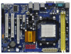
630a SATAII_3 (PORT 2.0) SATAII_1 (PORT 1.0) SATAII_4 (PORT 2.1) SATAII_2 (PORT 1.1) 22 Super I/O 21 AUDIO CODEC HD_AUDIO1 1 20 FLOPPY1 19 PCIE2 PCI1 PCI2 LPT1 1 RoHS 4Mb BIOS CMOS BATTERY CLRCMOS1 1 CHA_FAN1 1 USB4_5 PANEL 1 PLED PWRBTN 1 1 HDLED RESET USB6_7 SPEAKER1 1 18 - ASRock N68-GS | User Manual - Page 11
9 COM Port 10 PS/2 Keyboard Port (Purple) * For N68-GS motherboard, please refer to the table below for the LAN port LED Audio Deck" tool on your system. Please follow below instructions according to the OS you install. For Windows® 2000 / XP / XP 64-bit OS: Please click "VIA HD Audio - ASRock N68-GS | User Manual - Page 12
the power is switched off or the power cord is detached from the power supply. Failure to do so may cause severe damage to the motherboard, peripherals, and/or components. 1. Unplug the power cord from the wall socket before touching any component. 2. To avoid damaging the - ASRock N68-GS | User Manual - Page 13
. Make sure that the CPU and the heatsink are securely fastened and in good contact with each other. Then connect the CPU fan to the CPU FAN connector (CPU_FAN1, see Page 10, No. 2). For proper installation, please kindly refer to the instruction manuals of the CPU fan and the heatsink. 13 - ASRock N68-GS | User Manual - Page 14
2.3 Installation of Memory Modules (DIMM) N68-GS / N68-S motherboard provides two 240-pin DDR2 (Double Data Rate 2) DIMM slots, and supports Dual Channel Memory Technology. For dual channel configuration, you always need to install two identical (the same brand, speed, size and chiptype) memory - ASRock N68-GS | User Manual - Page 15
2.4 Expansion Slots (PCI and PCI Express Slots) There are 2 PCI slots and 2 PCI Express slots on this motherboard. PCI slots: PCI slots are used to install expansion cards that have the 32-bit PCI interface. PCIE slots: PCIE1 (PCIE x1 slot) is used - ASRock N68-GS | User Manual - Page 16
motherboard supports your system. Press to enter BIOS setup. Enter "Share Memory" option to motherboard. 4. Install the onboard VGA driver to your system. If you have installed the onboard VGA driver already, there is no need to install it again. 5. Set up a multi-monitor display. For Windows - ASRock N68-GS | User Manual - Page 17
short pin2 and pin3 on CLRCMOS1 for 5 seconds. However, please do not clear the CMOS right after you update the BIOS. If you need to clear the CMOS when you just finish updating the BIOS, you must boot up the system first, and then shut it down before you do the clear-CMOS action - ASRock N68-GS | User Manual - Page 18
end to the motherboard connect the black end to the IDE devices 80-conductor ATA 66/100/133 cable Note: Please refer to the instruction of your IDE device PORT 2.1) (PORT 1.1) These four Serial ATAII (SATAII) connectors support SATAII or SATA hard disk for internal storage devices. The current - ASRock N68-GS | User Manual - Page 19
two USB 2.0 headers on this motherboard. Each USB 2.0 header can support two USB 2.0 ports. Print audio devices. 1. High Definition Audio supports Jack Sensing, but the panel wire on the chassis must support HDA to function correctly. Please follow the instruction in our manual and chassis manual - ASRock N68-GS | User Manual - Page 20
p.10 No. 2) 4 3 2 1 GND +12V CPU_FAN_SPEED FAN_SPEED_CONTROL Please connect the CPU fan cable to this connector and match the black wire to the ground pin. Though this motherboard provides 4-Pin CPU fan (Quiet Fan) support, the 3-Pin CPU fan still can work successfully even without the fan speed - ASRock N68-GS | User Manual - Page 21
ATX 12V Power Connector (4-pin ATX12V1) (see p.10 No. 24) Please note that it is necessary to connect a power supply with ATX 12V plug to this connector. Failing to do so will cause power up failure. 21 - ASRock N68-GS | User Manual - Page 22
guide. Some default setting of SATAII hard disks may not be at SATAII mode, which operate with the best performance. In order to enable SATAII function, please follow the below instruction website for details: http://www.hitachigst.com/hdd/support/download.htm The above examples are just for your - ASRock N68-GS | User Manual - Page 23
adopts NVIDIA® GeForce 7025 / nForce 630a chipset that supports Serial ATA (SATA) / Serial ATAII (SATAII) hard disks and RAID functions. You may install SATA / SATAII hard disks on this motherboard for internal storage devices. This section will guide you to install the SATA / SATAII hard disks - ASRock N68-GS | User Manual - Page 24
is installed into system properly. The latest SATA / SATAII driver is available on our support website: www.asrock.com 4. Make sure to use the SATA power cable & data cable, which are from our motherboard package. 5. Please follow below instructions step by step to reduce the risk of HDD crash or - ASRock N68-GS | User Manual - Page 25
cable to (White) to the power supply 1x4-pin cable. the motherboard's SATAII connector. SATA power cable 1x4-pin power connector (White) Step attention, before you process the Hot Unplug: Please do follow below instruction sequence to process the Hot Unplug, improper procedure will cause the SATA - ASRock N68-GS | User Manual - Page 26
the "SATA Operation Mode" option to [IDE]. STEP 2: Make a SATA / SATAII Driver Diskette. A. Insert the ASRock Support CD into your optical drive to boot your system. (There are two ASRock Support CD in the motherboard gift box pack, please choose the one for Windows® 2000 / XP / XP 64-bit.) 26 - ASRock N68-GS | User Manual - Page 27
drivers into the floppy diskette. STEP 3: Set Up BIOS. A. Enter BIOS guide in the Support CD for proper configuration. Please refer to the BIOS RAID installation guide in the following path in the Support CD: .. \ RAID Installation Guide STEP 5: Install Windows® 2000 / Windows® XP / Windows - ASRock N68-GS | User Manual - Page 28
to boot your system, and follow the instruction to install Windows® VistaTM / Windows® VistaTM 64-bit OS on your system. When you see "Where do you want to install Windows? " page, please insert the ASRock Support CD into your optical drive, and click the "Load Driver" button on the left on the - ASRock N68-GS | User Manual - Page 29
the BIOS SETUP UTILITY to configure your system. The SPI Memory on the motherboard stores the BIOS SETUP UTILITY. You may run the BIOS SETUP off and then back on. Because the BIOS software is constantly being updated, the following BIOS setup screens and descriptions are for reference purpose - ASRock N68-GS | User Manual - Page 30
Exit System Overview System Time System Date [14:00:09] [Mon 02/16/2009] BIOS Version : N68-GS P1.00 Processor Type : AMD Phenom (tm) II X4 940 Processor (64bit) Processor Speed : 3000MHz Microcode Update : 100F42/1000086 L1 Cache Size : 512KB L2 Cache Size : 2048KB L3 Cache Size - ASRock N68-GS | User Manual - Page 31
Exit System Overview System Time System Date [14:00:09] [Mon 02/16/2009] BIOS Version : N68-S P1.00 Processor Type : AMD Phenom (tm) II X4 940 Processor (64bit) Processor Speed : 3000MHz Microcode Update : 100F42/1000086 L1 Cache Size : 512KB L2 Cache Size : 2048KB L3 Cache Size : 6144KB - ASRock N68-GS | User Manual - Page 32
. F6 key can be used for this operation. ASRock Instant Flash ASRock Instant Flash is a BIOS flash utility embeded in Flash ROM. This convenient BIOS update tool allows you to update system BIOS without entering operating systems first like MS-DOS or Windows. Just launch this tool and save the new - ASRock N68-GS | User Manual - Page 33
BIOS SETUP UTILITY Advanced CPU Configuration AM2 Boost Overclock Mode CPU Frequency (MHz) PCIE Frequency (MHz) CPU frequency/voltage. If Manual, multiplier and voltage will AM2 Boost This option appears only when you adopt AM2 CPU. If you set this option to [Enabled], you will enable ASRock AM2 - ASRock N68-GS | User Manual - Page 34
] and [Disabled]. If you install Windows® VistaTM and want to enable this appears only when you adopt AM2 CPU. When this option is set CPU. All processors support the Halt State (C1). The C1 state is supported through the native processor instructions HLT and MWAIT and requires no hardware support - ASRock N68-GS | User Manual - Page 35
BIOS SETUP UTILITY Advanced CPU Configuration AM2 Boost Overclock Mode CPU Frequency (MHz) PCIE Frequency (MHz) CPU AM2 CPU. This item will show when "Multiplier/Voltage Change" is set to [Manual]; otherwise, it will be hidden. The range of the value depends on the CPU you adopt on this motherboard - ASRock N68-GS | User Manual - Page 36
], [2CLK], [3CLK], [4CLK], [5CLK], [6CLK], [7CLK], [8CLK] and [9CLK]. The default value is [Auto]. TWRRD This option appears only when you adopt AM2 CPU. Use this to adjust TWRRD values. Configuration options: [Auto], [0CLK], [1CLK], [2CLK] and [3CLK]. The default value is [Auto]. TWRWR This option - ASRock N68-GS | User Manual - Page 37
TRDRD This option appears only when you adopt AM2 CPU. Use this to adjust TRWTTD values. Configuration options: [ , decreasing access contention. 3.4.2 Chipset Configuration BIOS SETUP UTILITY Advanced Chipset Settings Onboard LAN Onboard HD Audio Front Panel Share Memory Primary Graphics Adapter - ASRock N68-GS | User Manual - Page 38
]. Chipset Voltage Use this to select chipset voltage. Configuration options: [Auto], [1.25V], [1.30V], [1.35V] and [1.40V]. The default value is [Auto]. CPU Thermal Throttle Use this to enable CPU internal thermal control mechanism to keep the CPU from overheated. The default value is [Enabled]. 38 - ASRock N68-GS | User Manual - Page 39
3.4.3 ACPI Configuration BIOS SETUP UTILITY Advanced ACPI Settings Suspend To RAM Away Mode Support Restore on AC / Power resume. (STR refers to suspend to RAM.) Away Mode Support Use this item to enable or disable Away Mode support under Windows® XP Media Center OS. The default value is [Disabled - ASRock N68-GS | User Manual - Page 40
option to [Enabled] if you plan to use this motherboard to submit Windows® VistaTM certification. OSC Control Use this item to enable SATAII HDDs can not be accessed until you finish configuring RAID functions in NVIDIA BIOS / Windows RAID Utility. * If you install OS on SATA / SATAII HDDs, please - ASRock N68-GS | User Manual - Page 41
BIOS SETUP UTILITY Advanced IDE Master Device Vendor Size LBA Mode Block Mode PIO Mode Async DMA Ultra DMA S.M.A.R.T. :Hard Disk :MAXTOR 6L080J4 :80.0 GB :Supported :16Sectors :4 :MultiWord DMA-2 :Ultra DMA-6 :Supported hard disk > 512 MB under DOS and Windows; for Netware and UNIX user, select [ - ASRock N68-GS | User Manual - Page 42
Auto], [Enabled]. 32Bit Data Transfer Use this item to enable 32-bit access to maximize the IDE hard disk data transfer rate. 3.4.5PCIPnP Configuration BIOS SETUP UTILITY Advanced Advanced PCI / PnP Settings PCI Latency Timer PCI IDE BusMaster [32] [Enabled] Value in units of PCI clocks for PCI - ASRock N68-GS | User Manual - Page 43
Port Address Parallel Port Mode EPP Version ECP Mode DMA Channel Parallel Port IRQ [Enabled] [3F8 / IRQ4] [378] [ECP + EPP] [1.9] [DMA3] [IRQ7] Allow BIOS to Enable or Disable Floppy Controller. +F1 F9 F10 ESC Select Screen Select Item Change Option General Help Load Defaults Save and Exit Exit - ASRock N68-GS | User Manual - Page 44
Parallel Port Mode Use this item to set the operation mode of the parallel port. The default value is [ECP+EPP]. If this option is set to [ECP+EPP], it will show the EPP version in the following item, "EPP Version". Configuration options: [Normal], [Bi-Directional], and [ECP+EPP]. EPP Version Use - ASRock N68-GS | User Manual - Page 45
this item to enable or disable the USB 2.0 support. Legacy USB Support Use this option to select legacy support for USB devices. There are four configuration options: [Enabled], [Auto], [Disabled] and [BIOS Setup Only]. The default value is [BIOS Setup Only]. Please refer to below descriptions for - ASRock N68-GS | User Manual - Page 46
you to monitor the status of the hardware on your system, including the parameters of the CPU temperature, motherboard temperature, CPU fan speed, chassis fan speed, and the critical voltage. BIOS SETUP UTILITY Main Smart Advanced H/W Monitor Boot Security Exit Hardware Health Event Monitoring - ASRock N68-GS | User Manual - Page 47
this section, it will display the available devices on your system for you to configure the boot settings and the boot priority. BIOS SETUP UTILITY Main Smart Advanced H/W Monitor Boot Security Exit Boot Settings Boot Settings Configuration Configure Settings during System Boot. 1st Boot Device - ASRock N68-GS | User Manual - Page 48
section, you may set or change the supervisor/user password for the system. For the user password, you may also clear it. BIOS SETUP UTILITY Main Smart Advanced H/W Monitor Boot Security Exit Security Settings Supervisor Password : Not Installed User Password : Not Installed Change Supervisor - ASRock N68-GS | User Manual - Page 49
and exit setup?" Select [OK] to save the changes and exit the BIOS SETUP UTILITY. Discard Changes and Exit When you select this option, it message, "Discard changes and exit setup?" Select [OK] to exit the BIOS SETUP UTILITY without saving any changes. Discard Changes When you select this option - ASRock N68-GS | User Manual - Page 50
install the necessary drivers to activate the devices. 4.2.3 Utilities Menu The Utilities Menu shows the applications software that the motherboard supports. Click on a specific item then follow the installation wizard to install it. 4.2.4 Contact Information If you need to contact ASRock or want to
-
 1
1 -
 2
2 -
 3
3 -
 4
4 -
 5
5 -
 6
6 -
 7
7 -
8
-
9
-
10
-
11
-
12
-
13
-
14
-
15
-
16
-
17
-
18
-
19
-
20
-
21
-
22
-
23
-
24
-
25
-
26
-
27
-
28
-
29
-
30
-
31
-
32
-
33
-
34
-
35
-
36
-
37
-
38
-
39
-
40
-
41
-
42
-
43
-
44
-
45
-
46
-
47
-
48
-
49
-
50
 |
 |
1
N68-GS / N68-S
User Manual
Version 1.3
Published August 2009
Copyright©2009 ASRock INC. All rights reserved.