ASRock N68-S UCC User Manual
ASRock N68-S UCC Manual
 |
View all ASRock N68-S UCC manuals
Add to My Manuals
Save this manual to your list of manuals |
ASRock N68-S UCC manual content summary:
- ASRock N68-S UCC | User Manual - Page 1
N68-GS UCC / N68-S UCC User Manual Version 1.0 Published February 2010 Copyright©2010 ASRock INC. All rights reserved. 1 - ASRock N68-S UCC | User Manual - Page 2
purchaser for backup purpose, without written consent of ASRock Inc. Products and corporate names appearing in this manual may or may not be registered trademarks or copyrights USA ONLY The Lithium battery adopted on this motherboard contains Perchlorate, a toxic substance controlled in Perchlorate - ASRock N68-S UCC | User Manual - Page 3
1.2 Specifications 6 1.3 Motherboard Layout 11 1.4 I/O SATA / SATAII HDD Hot Plug Feature and Operation Guide ..... 25 2.12 Driver Installation Guide 27 2.13 Installing Windows® 7 / 7 64 Overclocking Technology 29 3 . BIOS SETUP UTILITY 30 3.1 Introduction 30 3.1.1 BIOS Menu Bar 30 3.1.2 - ASRock N68-S UCC | User Manual - Page 4
3.6 Boot Screen 49 3.6.1 Boot Settings Configuration 49 3.7 Security Screen 50 3.8 Exit Screen 51 4 . Software Support 52 4.1 Install Operating System 52 4.2 Support CD Information 52 4.2.1 Running Support CD 52 4.2.2 Drivers Menu 52 4.2.3 Utilities Menu 52 4.2.4 Contact Information 52 4 - ASRock N68-S UCC | User Manual - Page 5
you are using. www.asrock.com/support/index.asp 1.1 Package Contents One ASRock N68-GS UCC / N68-S UCC Motherboard (Micro ATX Form Factor: 9.6-in x 7.0-in, 24.4 cm x 17.8 cm) One ASRock N68-GS UCC / N68-S UCC Quick Installation Guide One ASRock N68-GS UCC / N68-S UCC Support CD Two Serial ATA (SATA - ASRock N68-S UCC | User Manual - Page 6
up to 1920x1440 @ 60Hz - 5.1 CH HD Audio (VIA® VT1708S / VT1705 Audio Codec) - N68-GS UCC Realtek Giga PHY RTL8211CL, speed 10/100/1000 Mb/s - N68-S UCC Realtek PHY RTL8201EL / 8201CL, speed 10/100 Mb/s - Supports Wake-On-LAN I/O Panel - 1 x PS/2 Mouse Port - 1 x PS/2 Keyboard Port - 1 x Serial Port - ASRock N68-S UCC | User Manual - Page 7
" - ACPI 1.1 Compliance Wake Up Events - Supports jumperfree - SMBIOS 2.3.1 Support - Supports Smart BIOS - Drivers, Utilities, AntiVirus Software (Trial Version), ASRock Software Suite (CyberLink DVD Suite and Creative Sound Blaster X-Fi MB) (OEM and Trial Version) - ASRock OC Tuner (see CAUTION 10 - ASRock N68-S UCC | User Manual - Page 8
motherboard supports CPU up to 95W. Please refer to our website for CPU support list. ASRock website http://www.asrock.com 2. UCC (Unlock CPU Core) feature simplifies AMD CPU activation. As long as a simple switch of the BIOS Setup Guide" on - ASRock N68-S UCC | User Manual - Page 9
key during the POST or press key to BIOS setup menu to access ASRock Instant Flash. Just launch this tool and save the new BIOS file to your USB flash drive, floppy disk or hard drive, then you can update your BIOS only in a few clicks without preparing an additional floppy diskette or - ASRock N68-S UCC | User Manual - Page 10
16. This motherboard supports ASRock AM2 Boost overclocking technology. If you enable this function in the BIOS setup, the memory performance will improve up to 12.5%, but the effect still depends on the AM2 CPU you adopt. Enabling this function will overclock - ASRock N68-S UCC | User Manual - Page 11
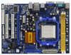
Motherboard Layout (N68-GS UCC / N68-S UCC) 12 17.8cm (7.0-in) PS2 Mouse PS2 Keyboard COM1 1 PS2_USB_PW1 DDRII_2 (64 bit, 240-pFinSmBod8u0le0) 3 DDRII_1 (64 bit, 240-pin module) AM2+/AM3 19 PCIE2 PCI1 PCI2 LPT1 1 RoHS 4Mb BIOS CMOS BATTERY CLRCMOS1 1 CHA_FAN1 1 USB4_5 PANEL - ASRock N68-S UCC | User Manual - Page 12
(N68-GS UCC / N68-S UCC) 1 2 3 4 5 10 9 8 1 PS/2 Mouse Port (Green) 2 RJ-45 Port 3 Line In (Light Blue) 4 Front Speaker (Lime) * 5 Microphone (Pink) 7 6 6 USB 2.0 Ports (USB01) 7 USB 2.0 Ports (USB23) 8 VGA Port 9 COM Port 10 PS/2 Keyboard Port (Purple) * For N68-GS motherboard, please - ASRock N68-S UCC | User Manual - Page 13
the power is switched off or the power cord is detached from the power supply. Failure to do so may cause severe damage to the motherboard, peripherals, and/or components. 1. Unplug the power cord from the wall socket before touching any component. 2. To avoid damaging the - ASRock N68-S UCC | User Manual - Page 14
Socket Lever 2.2 Installation of CPU Fan and Heatsink After you install the CPU into this motherboard, it is necessary to install a larger heatsink and cooling fan to dissipate heat. You 2). For proper installation, please kindly refer to the instruction manuals of the CPU fan and the heatsink. 14 - ASRock N68-S UCC | User Manual - Page 15
2.3 Installation of Memory Modules (DIMM) N68-GS UCC / N68-S UCC motherboard provides two 240-pin DDR2 (Double Data Rate 2) DIMM slots, and supports Dual Channel Memory Technology. For dual channel configuration, you always need to install two identical (the same brand, speed, size and chip-type) - ASRock N68-S UCC | User Manual - Page 16
2.4 Expansion Slots (PCI and PCI Express Slots) There are 2 PCI slots and 2 PCI Express slots on this motherboard. PCI slots: PCI slots are used to install expansion cards that have the 32-bit PCI interface. PCIE slots: PCIE1 (PCIE x1 slot) is used - ASRock N68-S UCC | User Manual - Page 17
2.5 Easy Multi Monitor Feature This motherboard supports Multi Monitor upgrade. With the internal the BIOS setup, the default value of "Share Memory", [Auto], will disable onboard VGA/D-Sub function when the add-on VGA card is inserted to this motherboard. 4. Install the onboard VGA driver to - ASRock N68-S UCC | User Manual - Page 18
short pin2 and pin3 on CLRCMOS1 for 5 seconds. However, please do not clear the CMOS right after you update the BIOS. If you need to clear the CMOS when you just finish updating the BIOS, you must boot up the system first, and then shut it down before you do the clear-CMOS action - ASRock N68-S UCC | User Manual - Page 19
blue end to the motherboard connect the black end to the IDE devices 80-conductor ATA 66/100/133 cable Note: Please refer to the instruction of your IDE device PORT 1.1) (PORT 0.1) These four Serial ATAII (SATAII) connectors support SATAII or SATA hard disk for internal storage devices. The - ASRock N68-S UCC | User Manual - Page 20
USB 2.0 headers on this motherboard. Each USB 2.0 header can support two USB 2.0 ports. supports Jack Sensing, but the panel wire on the chassis must support HDA to function correctly. Please follow the instruction in our manual and chassis manual audio panel. E. Enter BIOS Setup Utility. Enter Advanced - ASRock N68-S UCC | User Manual - Page 21
FAN_SPEED_CONTROL Please connect the CPU fan cable to this connector and match the black wire to the ground pin. Though this motherboard provides 4-Pin CPU fan (Quiet Fan) support, the 3-Pin CPU fan still can work successfully even without the fan speed control function. If you plan to connect - ASRock N68-S UCC | User Manual - Page 22
ATX 12V Power Connector (4-pin ATX12V1) (see p.11 No. 24) Please note that it is necessary to connect a power supply with ATX 12V plug to this connector. Failing to do so will cause power up failure. 22 - ASRock N68-S UCC | User Manual - Page 23
guide. Some default setting of SATAII hard disks may not be at SATAII mode, which operate with the best performance. In order to enable SATAII function, please follow the below instruction website for details: http://www.hitachigst.com/hdd/support/download.htm The above examples are just for your - ASRock N68-S UCC | User Manual - Page 24
adopts NVIDIA® GeForce 7025 / nForce 630a chipset that supports Serial ATA (SATA) / Serial ATAII (SATAII) hard disks and RAID functions. You may install SATA / SATAII hard disks on this motherboard for internal storage devices. This section will guide you to install the SATA / SATAII hard disks - ASRock N68-S UCC | User Manual - Page 25
is installed into system properly. The latest SATA / SATAII driver is available on our support website: www.asrock.com 4. Make sure to use the SATA power cable & data cable, which are from our motherboard package. 5. Please follow below instructions step by step to reduce the risk of HDD crash or - ASRock N68-S UCC | User Manual - Page 26
cable to (White) to the power supply 1x4-pin cable. the motherboard's SATAII connector. SATA power cable 1x4-pin power connector (White) Step attention, before you process the Hot Unplug: Please do follow below instruction sequence to process the Hot Unplug, improper procedure will cause the SATA - ASRock N68-S UCC | User Manual - Page 27
functions, please follow below steps. STEP 1: Set Up BIOS. A. Enter BIOS SETUP UTILITY Advanced screen Storage Configuration. B. Set the "SATA Operation Mode" option to [IDE]. STEP 2: Make a SATA / SATAII Driver Diskette. A. Insert the ASRock Support CD into your optical drive to boot your system - ASRock N68-S UCC | User Manual - Page 28
and copy SATA / SATAII drivers into the floppy diskette. STEP 3: Set Up BIOS. A. Enter BIOS SETUP UTILITY Advanced screen Storage guide in the Support CD for proper configuration. Please refer to the BIOS RAID installation guide in the following path in the Support CD: .. \ RAID Installation Guide - ASRock N68-S UCC | User Manual - Page 29
\ RAID Installation Guide NOTE. For Windows® 7 / 7 64-bit users, you do not need to load RAID driver from ASRock support CD. Please use the native driver to install Windows® 7 / 7 64-bit OS, and then install ASRock All-in-1 driver. 2.15 Untied Overclocking Technology This motherboard supports Untied - ASRock N68-S UCC | User Manual - Page 30
the BIOS SETUP UTILITY to configure your system. The SPI Memory on the motherboard stores the BIOS SETUP UTILITY. You may run the BIOS SETUP off and then back on. Because the BIOS software is constantly being updated, the following BIOS setup screens and descriptions are for reference purpose - ASRock N68-S UCC | User Manual - Page 31
Exit System Overview System Time System Date [14:00:09] [Thu 02/04/2010] BIOS Version : N68-GS UCC P1.00 Processor Type : AMD Phenom (tm) II X4 940 Processor (64bit) Processor Speed : 3000MHz Microcode Update : 100F42/1000086 L1 Cache Size : 512KB L2 Cache Size : 2048KB L3 Cache Size - ASRock N68-S UCC | User Manual - Page 32
Exit System Overview System Time System Date [14:00:09] [Thu 02/04/2010] BIOS Version : N68-S UCC P1.00 Processor Type : AMD Phenom (tm) II X4 940 Processor (64bit) Processor Speed : 3000MHz Microcode Update : 100F42/1000086 L1 Cache Size : 512KB L2 Cache Size : 2048KB L3 Cache Size - ASRock N68-S UCC | User Manual - Page 33
the USB flash drive or hard drive must use FAT32/16/12 file system. If you execute ASRock Instant Flash utility, the utility will show the BIOS files and their respective information. Select the proper BIOS file to update your BIOS, and reboot your system after BIOS update process completes. 33 - ASRock N68-S UCC | User Manual - Page 34
malfunction. 3.4.1CPU Configuration BIOS SETUP UTILITY Advanced CPU Configuration voltage will be left at the rated frequency/voltage. If Manual, multiplier and voltage will be set based on User set this option to [Enabled], you will enable ASRock AM2 Boost function, which will improve the memory - ASRock N68-S UCC | User Manual - Page 35
support the Halt State (C1). The C1 state is supported through the native processor instructions HLT and MWAIT and requires no hardware support All Cores]. Unlock CPU Core UCC (Unlock CPU Core) feature simplifies AMD CPU activation. As long as a simple switch of the BIOS option "Unlock CPU Core", - ASRock N68-S UCC | User Manual - Page 36
UCC feature is supported with AM2+ / AM3 CPU only, and in addition, not every AM2+ / AM3 CPU can support default value for system stability. BIOS SETUP UTILITY Advanced CPU Configuration [Manual]; otherwise, it will be hidden. The range of the value depends on the CPU you adopt on this motherboard - ASRock N68-S UCC | User Manual - Page 37
, for safety and system stability, it is not recommended to adjust the value of this item. Memory Clock This item can be set by the code using [Auto]. You can set one of the standard values as listed: [200MHz (DDRII400)], [266MHz (DDRII533)], [333MHz (DDRII667)] and [400MHz (DDRII800)]. If you adopt - ASRock N68-S UCC | User Manual - Page 38
TWTR Use this to adjust TWTR values. Configuration options: [Auto], [1CLK], [2CLK] and [3CLK]. The default value is [Auto]. TRWTTO This option appears only when you adopt AM2 CPU. Use this to adjust TRWTTD values. Configuration options: [Auto], [2CLK], [3CLK], [4CLK], [5CLK], [6CLK], [7CLK], [8CLK] - ASRock N68-S UCC | User Manual - Page 39
BIOS If you select [Auto], the onboard HD Audio will be disabled when PCI Sound Card is plugged. Front Panel Select [Auto], [Enabled] or [Disabled] for Primary Graphics Adapter This item will switch the PCI Bus scanning order while searching for video card. It allows you to select the type of Primary - ASRock N68-S UCC | User Manual - Page 40
Chipset Voltage Use this to select chipset voltage. Configuration options: [Auto], [1.25V], [1.30V], [1.35V] and [1.40V]. The default value is [Auto]. CPU Thermal Throttle Use this to enable CPU internal thermal control mechanism to keep the CPU from overheated. The default value is [Enabled]. 40 - ASRock N68-S UCC | User Manual - Page 41
3.4.3 ACPI Configuration BIOS SETUP UTILITY Advanced ACPI Settings Suspend To RAM Away Mode Support Restore on AC / Power Loss disable the Suspend-to-RAM feature. Select [Auto] will enable this feature if the OS supports it. If you set this item to [Disabled], the function "Repost Video on STR - ASRock N68-S UCC | User Manual - Page 42
[Enabled] if you plan to use this motherboard to submit Windows® VistaTM certification. OSC Control not be accessed until you finish configuring RAID functions in NVIDIA BIOS / Windows RAID Utility. * If you install OS on SATA instruction, which can be applied to the configurations of "IDE1 Slave" as - ASRock N68-S UCC | User Manual - Page 43
BIOS SETUP UTILITY Advanced IDE Master Device Vendor Size LBA Mode Block Mode PIO Mode Async DMA Ultra DMA S.M.A.R.T. :Hard Disk :MAXTOR 6L080J4 :80.0 GB :Supported :16Sectors :4 :MultiWord DMA-2 :Ultra DMA-6 :Supported selecting the hard disk information into BIOS, use a disk utility, such as - ASRock N68-S UCC | User Manual - Page 44
Auto], [Enabled]. 32Bit Data Transfer Use this item to enable 32-bit access to maximize the IDE hard disk data transfer rate. 3.4.5PCIPnP Configuration BIOS SETUP UTILITY Advanced Advanced PCI / PnP Settings PCI Latency Timer PCI IDE BusMaster [32] [Enabled] Value in units of PCI clocks for PCI - ASRock N68-S UCC | User Manual - Page 45
Port Address Parallel Port Mode EPP Version ECP Mode DMA Channel Parallel Port IRQ [Enabled] [3F8 / IRQ4] [378] [ECP + EPP] [1.9] [DMA3] [IRQ7] Allow BIOS to Enable or Disable Floppy Controller. +F1 F9 F10 ESC Select Screen Select Item Change Option General Help Load Defaults Save and Exit Exit - ASRock N68-S UCC | User Manual - Page 46
Parallel Port Mode Use this item to set the operation mode of the parallel port. The default value is [ECP+EPP]. If this option is set to [ECP+EPP], it will show the EPP version in the following item, "EPP Version". Configuration options: [Normal], [Bi-Directional], and [ECP+EPP]. EPP Version Use - ASRock N68-S UCC | User Manual - Page 47
this item to enable or disable the USB 2.0 support. Legacy USB Support Use this option to select legacy support for USB devices. There are four configuration options: [Enabled], [Auto], [Disabled] and [BIOS Setup Only]. The default value is [BIOS Setup Only]. Please refer to below descriptions for - ASRock N68-S UCC | User Manual - Page 48
the status of the hardware on your system, including the parameters of the CPU temperature, motherboard temperature, CPU fan speed, chassis fan speed, and the critical voltage. BIOS SETUP UTILITY Main Smart Advanced H/W Monitor Boot Security Exit Hardware Health Event Monitoring CPU Temperature - ASRock N68-S UCC | User Manual - Page 49
this section, it will display the available devices on your system for you to configure the boot settings and the boot priority. BIOS SETUP UTILITY Main Smart Advanced H/W Monitor Boot Security Exit Boot Settings Boot Settings Configuration Configure Settings during System Boot. 1st Boot Device - ASRock N68-S UCC | User Manual - Page 50
section, you may set or change the supervisor/user password for the system. For the user password, you may also clear it. BIOS SETUP UTILITY Main Smart Advanced H/W Monitor Boot Security Exit Security Settings Supervisor Password : Not Installed User Password : Not Installed Change Supervisor - ASRock N68-S UCC | User Manual - Page 51
and exit setup?" Select [OK] to save the changes and exit the BIOS SETUP UTILITY. Discard Changes and Exit When you select this option, it message, "Discard changes and exit setup?" Select [OK] to exit the BIOS SETUP UTILITY without saving any changes. Discard Changes When you select this option - ASRock N68-S UCC | User Manual - Page 52
install the necessary drivers to activate the devices. 4.2.3 Utilities Menu The Utilities Menu shows the applications software that the motherboard supports. Click on a specific item then follow the installation wizard to install it. 4.2.4 Contact Information If you need to contact ASRock or want to
-
 1
1 -
 2
2 -
 3
3 -
 4
4 -
 5
5 -
 6
6 -
 7
7 -
8
-
9
-
10
-
11
-
12
-
13
-
14
-
15
-
16
-
17
-
18
-
19
-
20
-
21
-
22
-
23
-
24
-
25
-
26
-
27
-
28
-
29
-
30
-
31
-
32
-
33
-
34
-
35
-
36
-
37
-
38
-
39
-
40
-
41
-
42
-
43
-
44
-
45
-
46
-
47
-
48
-
49
-
50
-
51
-
52
 |
 |
1
N68-GS UCC /
N68-S UCC
User Manual
Version 1.0
Published February 2010
Copyright©2010 ASRock INC. All rights reserved.