ASRock P4 Combo User Manual
ASRock P4 Combo Manual
 |
View all ASRock P4 Combo manuals
Add to My Manuals
Save this manual to your list of manuals |
ASRock P4 Combo manual content summary:
- ASRock P4 Combo | User Manual - Page 1
P4 Combo User Manual Version 1.0 Published July 2004 Copyright©2004 ASRock INC. All rights reserved. 1 - ASRock P4 Combo | User Manual - Page 2
any form or by any means, except duplication of documentation by the purchaser for backup purpose, without written consent of ASRock Inc. Products and corporate names appearing in this manual may or may not be registered trademarks or copyrights of their respective companies, and are used only for - ASRock P4 Combo | User Manual - Page 3
Specifications 6 1.3 Motherboard Layout 8 1.4 ASRock I/O PlusTM 9 2 Installation 10 Pre-installation Precautions 10 2.1 CPU Sockets 11 2.2 CPU Serial ATA (SATA) Hard Disks Installation 22 3 BIOS SETUP UTILITY 23 3.1 Introduction 23 3.1.1 BIOS Menu Bar 23 3.1.2 Navigation Keys 24 3.2 Main - ASRock P4 Combo | User Manual - Page 4
4 Software Support 38 4.1 Install Operating System 38 4.2 Support CD Information 38 4.2.1 Running Support CD 38 4.2.2 Drivers Menu 38• 4.2.3 Utilities Menu 38 4.2.4 ASRock "PC-DIY Live Demo" Program 38 4.2.5 "LGA 775 CPU Installation Live Demo" Program ... 38 4.2.6 Contact Information 38 4 - ASRock P4 Combo | User Manual - Page 5
Contents ASRock P4 Combo Motherboard (ATX Form Factor: 12.0-in x 9.6-in, 30.5 cm x 24.4 cm) ASRock P4 Combo Quick Installation Guide ASRock P4 Combo Support CD (including LGA 775 CPU Installation Live Demo) One 80-conductor Ultra ATA 66/100 IDE Ribbon Cable One Ribbon Cable for a 3.5-in Floppy Drive - ASRock P4 Combo | User Manual - Page 6
Intel® Pentium® 4 / Celeron® processor (in 775-land LGA package) 2. 478-Pin Socket Supporting Intel® Pentium® 4 / Celeron® (Prescott, Northwood, Willimate) processor Chipsets: North Bridge: Intel® 848P chipset, FSB @ 800 / 533 / 400MHz, supports Hyper-Threading Technology (see CAUTION 1) South - ASRock P4 Combo | User Manual - Page 7
: OS: AMI legal BIOS, Supports "Plug and Play", ACPI 1.1 compliance wake up events, CPU frequency stepless control ( . CPU FSB Frequency Memory Support Frequency 800 DDR266, DDR320*, DDR400 533 DDR266, DDR333 400 DDR266 * When you use an FSB800-CPU on this motherboard, it will run at DDR320 - ASRock P4 Combo | User Manual - Page 8
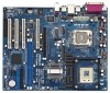
Motherboard 2MB BIOS P4-775 FSB1 1 P4-478 J3 1111111111 1111111111 Intel 848P Chipset 1.5V_AGP1 PCI1 P4 Combo Prescott 800 FSB800 USB2.0 DDR400 5.1CH AGP8X SATA CD1 AUX1 AUDIO1 1 JR1 JL1 AUDIO 775-Pin CPU Socket 4 CPU Heatsink Retention Module (for 478-Pin CPU) 5 478-Pin CPU Socket - ASRock P4 Combo | User Manual - Page 9
1.4 ASRock I/O PlusTM 1 11 10 9 1 Parallel Port 2 RJ-45 Port 3 Line In (Light Blue) 4 Line Out (Lime) 5 Microphone (Pink) 6 Shared USB 2.0 Ports (USB45) 2 3 4 5 8 7 6 7 USB 2.0 Ports (USB01) 8 USB 2.0 - ASRock P4 Combo | User Manual - Page 10
2. Installation P4 Combo is an ATX form factor (12.0-in x 9.6-in, 30.5 cm x 24.4 cm) motherboard. Before you install the motherboard, study the configuration of your chassis to ensure that the motherboard fits into it. Pre-installation Precautions Take note of the following precautions before you - ASRock P4 Combo | User Manual - Page 11
types of CPU sockets. You may choose to install either Intel 775-Pin CPU or Intel 478-Pin CPU into this motherboard. However, to avoid instability and damage to the system, please do not install both of them into this motherboard. Important: If you install a 775-Pin CPU into this motherboard, it is - ASRock P4 Combo | User Manual - Page 12
with two types of CPU sockets. You may choose to install either Intel 775-Pin CPU or Intel 478-Pin CPU into this motherboard. However, to avoid instability and damage to the system, please do not install both of them into this motherboard. I. For the installation of Intel 775-Pin CPU, please follow - ASRock P4 Combo | User Manual - Page 13
key notch orientation key notch Pin1 alignment key alignment key 775-Pin CPU 775-Pin Socket For proper inserting, please ensure to match the two finger and thumb to support the load plate edge, engage PnP cap with right hand thumb and peel the cap from the socket while pressing on center of - ASRock P4 Combo | User Manual - Page 14
II. For the installation of Intel 478-Pin CPU, please follow the steps below. Step 1. Step 2. Step 3. Unlock the socket by lifting the lever up to a 90° angle. Position the CPU directly above the socket such that its marked corner matches the base of the socket lever. Carefully insert the CPU into - ASRock P4 Combo | User Manual - Page 15
proper installation, please kindly refer to the instruction manuals of your CPU fan and heatsink. Below is an example to illustrate the installation of the heatsink for 775-Pin CPU. Step 1. Apply thermal interface material onto center of IHS on the socket surface. Step 2. Step 3. Step 4. Place the - ASRock P4 Combo | User Manual - Page 16
2.4 Installation of Memory Modules (DIMM) P4 Combo motherboard provides two 184-pin DDR (Double Data Rate) break The DIMM only fits in one correct orientation. It will cause permanent damage to the motherboard and the DIMM if you force the DIMM into the slot at incorrect orientation. Step 3. Firmly - ASRock P4 Combo | User Manual - Page 17
Slots) There are 4 PCI slots and 1 AGP slot on P4 Combo motherboard. PCI slots: PCI slots are used to install expansion cards that have the 32-bit PCI interface. AGP slot: The AGP slot is used to install a graphics card. The ASRock AGP slot has a special locking mechanism which can securely fasten - ASRock P4 Combo | User Manual - Page 18
If the jumpers JL1 and JR1 are short, both the front panel and the rear panel audio connectors can work. Clear CMOS (CLRCMOS0) (see p.8 No. 12) 2-pin jumper Note: CMOS right after you update the BIOS. If you need to clear the CMOS when you just finish updating the BIOS, you must boot up the system - ASRock P4 Combo | User Manual - Page 19
to the IDE devices 80-conductor ATA 66/100 cable Note: If you use only one IDE device on this motherboard, please set the IDE device as "Master". Please refer to the instruction of your IDE device vendor for the details. Besides, to optimize compatibility and performance, please connect your hard - ASRock P4 Combo | User Manual - Page 20
cable to the power connector on each drive. Then connect the white end of SATA is shared with the USB 2.0 ports 4,5 on ASRock I/O PlusTM. When using the front panel USB supports an optional wireless transmitting and receiving infrared module. These connectors allow you to receive stereo audio input - ASRock P4 Combo | User Manual - Page 21
System Panel Header (9-pin PANEL1) (see p.8 No. 13) Chassis Speaker Header (4-pin SPEAKER 1) (see p.8 No. 14) Chassis Fan Connector (3-pin CHA_FAN1) (see p.8 No. 15) PLED+ PLEDPWRBTN# GND 1 DUMMY RESET# GND HDLEDHDLED+ 1 SPEAKER DUMMY DUMMY +5V GND +12V CHA_FAN_SPEED This header accommodates - ASRock P4 Combo | User Manual - Page 22
Intel ICH5 south bridge chipset that supports Serial ATA (SATA) hard disks. You may install SATA hard disks on this motherboard for internal storage devices. This section will guide you to install the SATA hard disks. STEP 1: Install the SATA hard disks into the drive bays of your chassis. STEP - ASRock P4 Combo | User Manual - Page 23
UTILITY 3.1 Introduction This section explains how to use the BIOS SETUP UTILITY to configure your system. The BIOS FWH chip on the motherboard stores the BIOS SETUP UTILITY. You may run the BIOS SETUP UTILITY when you start up the computer. Please press during the Power-On-Self-Test (POST - ASRock P4 Combo | User Manual - Page 24
UTILITY Main Advanced H/W Monitor Boot Security Exit System Overview System Time System Date [14:00:09] [Wed 07/07/2004] BIOS Version : P4 COMBO BIOS P1.00 Processor Type : Intel (R) Pentium (R) 4 CPU 2.40 GHz Processor Speed : 2400 MHz Cache Size : 512KB Microcode Update : 0F29/17 - ASRock P4 Combo | User Manual - Page 25
may cause the system to malfunction. 3.3.1 CPU Configuration BIOS SETUP UTILITY Advanced CPU Configuration CPU Host Frequency Actual Frequency . CPU Host Frequency While entering setup, BIOS auto detects the present CPU host frequency of this motherboard. The actual CPU host frequency will show - ASRock P4 Combo | User Manual - Page 26
of this motherboard. CPU Thermal Throttling You may select [Enabled] to enable P4 CPU internal thermal does not support Hyper-Threading technology. 3.3.2 Chipset Configuration BIOS SETUP UTILITY / AGP] [64MB] OnBoard LAN OnBoard AC'97 Audio [Enabled] [Auto] Options 133MHz 166MHz 200MHz Auto ( - ASRock P4 Combo | User Manual - Page 27
], [2.5], [2], and [3]. Please note that the configuration option [3] is available only for FSB 800 and FSB 533. DRAM RAS# Precharge This controls the idle clocks after a precharge command is or disable the "OnBoard LAN" feature. OnBoard AC'97 Audio Select [Auto] or [Disabled] for the onboard AC'97 - ASRock P4 Combo | User Manual - Page 28
3.3.3 ACPI Configuration Advanced BIOS SETUP UTILITY ACPI Settings Suspend To RAM Restore on AC / auto-detect or disable the Suspend-toRAM feature. Select [Auto] will enable this feature if the OS supports it. Restore on AC/Power Loss Use this item to set the power state after an unexpected AC/ - ASRock P4 Combo | User Manual - Page 29
3.3.4 IDE Configuration BIOS SETUP UTILITY Advanced IDE Configuration OnBoard IDE Operate is set to [SATA + Sec IDE], then the primary IDE will not work. Because Intel® ICH5 south bridge only supports four IDE devices under legacy OS (Windows ME / 98SE), you have to choose either [Pri IDE + SATA] - ASRock P4 Combo | User Manual - Page 30
as the example in the following instruction, which can be applied to the .0 GB :Supported :16Sectors :4 :MultiWord DMA-2 :Ultra DMA-5 :Supported [Auto] drive. After selecting the hard disk information into BIOS, use a disk utility, such as FDISK, to partition and format the new IDE hard disk drives - ASRock P4 Combo | User Manual - Page 31
[Enabled]. 32-Bit Data Transfer Use this item to enable 32-bit access to maximize the IDE hard disk data transfer rate. 3.3.5 PCIPnP Configuration BIOS SETUP UTILITY Advanced PCI / PnP Configuration PCI Latency Timer PCI IDE BusMaster [32] [Enabled] Value in units of PCI clocks for PCI device - ASRock P4 Combo | User Manual - Page 32
3.3.6 Floppy Configuration In this section, you may configure the type of your floppy drive. BIOS SETUP UTILITY Advanced Floppy Configuration Floppy A Floppy B [1.44 MB 312"] [Disabled] Select the type of floppy drive connected to the system. +F1 F9 F10 ESC Select Screen Select Item Change - ASRock P4 Combo | User Manual - Page 33
Parallel Port Address Use this item to set the address for the onboard parallel port or disable it. Configuration options: [Disabled], [378], and [278]. Parallel Port Mode Use this item to set the operation mode of the parallel port. The default value is [ECP+EPP]. If this option is set to [ECP+EPP - ASRock P4 Combo | User Manual - Page 34
there is no USB device connected, "Auto" option will disable the legacy USB support. 3.4 Hardware Health Event Monitoring Screen In this section, it allows you to temperature, motherboard temperature, CPU fan speed, chassis fan speed, and the critical voltage. Main Advanced BIOS SETUP UTILITY - ASRock P4 Combo | User Manual - Page 35
the boot settings and the boot priority. Main Advanced BIOS SETUP UTILITY H/W Monitor Boot Security Exit Boot Settings Boot Settings Configuration Boot Device Priority Hard Disk Drives Removable Drives CD / DVD Drives Configure Settings during System Boot. Select Screen Select Item - ASRock P4 Combo | User Manual - Page 36
In this section, you may specify the boot sequence from the available devices in your system. BIOS SETUP UTILITY Boot Boot Device Priority 1st Boot Device 2nd Boot Device 3rd Boot Device [1st FLOPPY DRIVE] [HDD: PM-MAXTOR 6L08] [CD / DVD] Specifies the boot sequence from the available devices - ASRock P4 Combo | User Manual - Page 37
and exit setup?" Select [OK] to save the changes and exit the BIOS SETUP UTILITY. Discard Changes and Exit When you select this option, it message, "Discard changes and exit setup?" Select [OK] to exit the BIOS SETUP UTILITY without saving any changes. Discard Changes When you select this option - ASRock P4 Combo | User Manual - Page 38
This motherboard is equipped with Intel LGA 775 socket, which is a new CPU socket interface that Intel has released. Since it has several tiny pins, whcih are easily to be damaged by improper handling, ASRock sincerely presents you a clear installation guide through this "LGA 775 CPU Installation
-
 1
1 -
 2
2 -
 3
3 -
 4
4 -
 5
5 -
 6
6 -
 7
7 -
8
-
9
-
10
-
11
-
12
-
13
-
14
-
15
-
16
-
17
-
18
-
19
-
20
-
21
-
22
-
23
-
24
-
25
-
26
-
27
-
28
-
29
-
30
-
31
-
32
-
33
-
34
-
35
-
36
-
37
-
38
 |
 |

1
P4 Combo
User Manual
Version 1.0
Published July 2004
Copyright©2004 ASRock INC. All rights reserved.