ASRock P41C-DE User Manual
ASRock P41C-DE Manual
 |
View all ASRock P41C-DE manuals
Add to My Manuals
Save this manual to your list of manuals |
ASRock P41C-DE manual content summary:
- ASRock P41C-DE | User Manual - Page 1
P41C-DE User Manual Version 1.0 Published October 2009 Copyright©2009 ASRock INC. All rights reserved. 1 - ASRock P41C-DE | User Manual - Page 2
any form or by any means, except duplication of documentation by the purchaser for backup purpose, without written consent of ASRock Inc. Products and corporate names appearing in this manual may or may not be registered trademarks or copyrights of their respective companies, and are used only for - ASRock P41C-DE | User Manual - Page 3
28 2.11 Serial ATA (SATA) / Serial ATAII (SATAII) Hard Disks Installation 29 2.12 Driver Installation Guide 29 2.13 Untied Overclocking Technology 29 3 BIOS SETUP UTILITY 30 3.1 Introduction 30 3.1.1 BIOS Menu Bar 30 3.1.2 Navigation Keys 31 3.2 Main Screen 31 3.3 OC Tweaker Screen 32 - ASRock P41C-DE | User Manual - Page 4
3.7 Security Screen 53 3.8 Exit Screen 54 4 Software Support 55 4.1 Install Operating System 55 4.2 Support CD Information 55 4.2.1 Running Support CD 55 4.2.2 Drivers Menu 55 4.2.3 Utilities Menu 55 4.2.4 Contact Information 55 4 - ASRock P41C-DE | User Manual - Page 5
guide to BIOS setup and information of the Support CD. Because the motherboard specifications and the BIOS software might be updated, the content of this manual will be subject to change without notice. In case any modifications of this manual occur, the updated version will be available on ASRock - ASRock P41C-DE | User Manual - Page 6
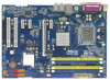
Express x16 slot - 3 x PCI Express x1 slots - 2 x PCI slots - 7.1 CH Windows® VistaTM Premium Level HD Audio (VIA® VT1708S Audio Codec) - PCIE x1 Gigabit LAN 10/100/1000 Mb/s - Atheros® AR8131L - Supports Wake-On-LAN I/O Panel - 1 x PS/2 Mouse Port - 1 x PS/2 Keyboard Port - 1 x Parallel Port (ECP - ASRock P41C-DE | User Manual - Page 7
Connector BIOS Feature Support CD Unique Feature Hardware Monitor OS Certifications - HD Audio Jack: Side Speaker/Rear Speaker/Central/Bass/ Line in/Front Speaker/Microphone (see CAUTION 7) - 4 x SATAII 3.0 Gb/s connectors (No Support for RAID and "Hot Plug" functions) (see CAUTION 8) - 1 x ATA100 - ASRock P41C-DE | User Manual - Page 8
.asrock.com WARNING Please realize that there is a certain risk involved with overclocking, including adjusting the setting in the BIOS, This motherboard supports Dual Channel Memory Technology. Before you implement Dual Channel Memory Technology, make sure to read the installation guide of memory - ASRock P41C-DE | User Manual - Page 9
website for the operation procedures of Intelligent Energy Saver. ASRock website: http://www.asrock.com 12. ASRock Instant Flash is a BIOS flash utility embedded in Flash ROM. This convenient BIOS update tool allows you to update system BIOS without entering operating systems first like MS-DOS or - ASRock P41C-DE | User Manual - Page 10
15. While CPU overheat is detected, the system will automatically shutdown. Before you resume the system, please check if the CPU fan on the motherboard functions properly and unplug the power cord, then plug it back again. To improve heat dissipation, remember to spray thermal grease between the - ASRock P41C-DE | User Manual - Page 11
G41 Chipset PCIE1 EuP Ready LAN PCIE2 PHY RoHS P41C-DE IDE1 CHA_FAN1 SATAII_4 SATAII_2 Super IO PCIE3 PCIE4 Intel ICH7 SATAII_3 AUDIO CODEC HD_AUDIO1 1 HDMI_SPDIF1 1 FLOPPY1 PCI1 PCI2 1 IR1 8Mb BIOS 2.0 Header (USB6_7, Blue) 2 775-Pin CPU Socket 18 BIOS SPI Chip 3 2 x 240- - ASRock P41C-DE | User Manual - Page 12
below for connection details in accordance with the type of speaker you use. TABLE for Audio Output Connection Audio Output Channels Front Speaker Rear Speaker Central / Bass Side Speaker (No. 8) (No. 5) (No. 6) (No. 4) 2 V -- -- -- 4 V V -- -- 6 V V V -- 8 V V V V 12 - ASRock P41C-DE | User Manual - Page 13
To enable Multi-Streaming function, you need to connect a front panel audio cable to the front panel audio header. After restarting your computer, you will find "VIA HD Audio Deck" tool on your system. Please follow below instructions according to the OS you install. For Windows® XP / XP 64-bit - ASRock P41C-DE | User Manual - Page 14
Chapter 2 Installation P41C-DE is an ATX form factor (12.0" x 8.4", 30.5 x 21.3 cm) motherboard. Before components or change any motherboard settings. 1. Unplug the power cord from the wall socket before touching any component. 2. To avoid damaging the motherboard components due to static - ASRock P41C-DE | User Manual - Page 15
2.3 CPU Installation For the installation of Intel 775-LAND CPU, please follow the steps below. 775-Pin Socket Overview Before you insert the 775-LAND CPU into the socket, please check if the CPU surface is unclean or if there is any bent pin on the socket. Do not force to insert the CPU into the - ASRock P41C-DE | User Manual - Page 16
finger and thumb to support the load plate edge, engage PnP cap with right hand thumb and peel the cap from the socket while pressing on center 2. This cap must be placed if returning the motherboard for after service. Step 4. Close the socket: Step 4-1. Rotate the load plate onto the IHS. Step 4-2. - ASRock P41C-DE | User Manual - Page 17
installation, please kindly refer to the instruction manuals of your CPU fan and heatsink. Below is an example to illustrate the installation of the heatsink for 775-LAND CPU. Step 1. Apply thermal interface material onto center of IHS on the socket surface. Step 2. Step 3. Step 4. Place the - ASRock P41C-DE | User Manual - Page 18
) This motherboard provides two 240-pin DDR2 (Double Data Rate 2) DIMM slots and two 240-pin DDR3 (Double Data Rate 3) DIMM slots, and supports Dual Channel Memory Technology. For dual channel configuration, you always need to install identical (the same brand, speed, size and chip-type) DDR2/DDR3 - ASRock P41C-DE | User Manual - Page 19
Installing a DIMM Please make sure to disconnect power supply before adding or removing DIMMs or the system components. Step 1. Step 2. Unlock a DIMM slot by pressing the retaining clips outward. Align a DIMM on the slot such that the notch on the DIMM matches the break on the slot. notch break - ASRock P41C-DE | User Manual - Page 20
2.6 Expansion Slots (PCI and PCI Express Slots) There are 2 PCI slots and 4 PCI Express slots on this motherboard. PCI slots: PCI slots are used to install expansion cards that have the 32-bit PCI interface. PCIE slots: PCIE1 / PCIE3 / PCIE4 (PCIE x1 slot) is used for PCI Express cards with x1 lane - ASRock P41C-DE | User Manual - Page 21
short pin2 and pin3 on CLRCMOS1 for 5 seconds. However, please do not clear the CMOS right after you update the BIOS. If you need to clear the CMOS when you just finish updating the BIOS, you must boot up the system first, and then shut it down before you do the clear-CMOS action - ASRock P41C-DE | User Manual - Page 22
this motherboard, you need to adjust the jumpers. Please follow the instructions below to set up the jumpers. Otherwise, the CPU and memory or FSB1066 CPU, and try to overclock to FSB1333 (by BIOS setting) you may face the problem, that DRAM frequency will be overclocked very high. Please use jumper - ASRock P41C-DE | User Manual - Page 23
-conductor ATA 66/100 cable Note: Please refer to the instruction of your IDE device vendor for the details. SATAII_1 SATAII_3 ) (SATAII_4: see p.11, No. 11) These Serial ATAII (SATAII) connectors support SATAII or SATA hard disk for internal storage devices. The current SATAII interface allows - ASRock P41C-DE | User Manual - Page 24
audio devices. 1. High Definition Audio supports Jack Sensing, but the panel wire on the chassis must support HDA to function correctly. Please follow the instruction in our manual and chassis manual for HD audio panel only. You don't need to connect them for AC'97 audio panel. E. Enter BIOS Setup - ASRock P41C-DE | User Manual - Page 25
this connector and match 3 CPU_FAN_SPEED 4 FAN_SPEED_CONTROL the black wire to the ground pin. Though this motherboard provides 4-Pin CPU fan (Quiet Fan) support, the 3-Pin CPU fan still can work successfully even without the fan speed control function. If you plan to connect the 3-Pin CPU - ASRock P41C-DE | User Manual - Page 26
Pin ATX 12V Power Supply Installation 8 4 HDMI_SPDIF Header (3-pin HDMI_SPDIF1) (see p.11 No. 22) 1 GND SPDIFOUT +5V HDMI_SPDIF header, providing SPDIF audio output to HDMI VGA card, allows the system to connect HDMI Digital TV/ projector/LCD devices. Please connect the HDMI_SPDIF connector of - ASRock P41C-DE | User Manual - Page 27
Guide HDMI (High-Definition Multi-media Interface) is an all-digital audio/video specification, which provides an interface between any compatible digital audio/ video source, such as a set-top box, DVD player, A/V receiver and a compatible digital audio audio installation guide on page manual manual - ASRock P41C-DE | User Manual - Page 28
guide. Some default setting of SATAII hard disks may not be at SATAII mode, which operate with the best performance. In order to enable SATAII function, please follow the below instruction website for details: http://www.hitachigst.com/hdd/support/download.htm The above examples are just for your - ASRock P41C-DE | User Manual - Page 29
. STEP 4: Connect the other end of the SATA data cable to the SATA / SATAII hard disk. 2.12 Driver Installation Guide To install the drivers to your system, please insert the support CD to your optical drive first. Then, the drivers compatible to your system can be auto-detected and listed on the - ASRock P41C-DE | User Manual - Page 30
Power-On-Self-Test (POST) to enter the BIOS SETUP UTILITY, otherwise, POST will continue with its test routines. If you wish to enter the BIOS SETUP UTILITY after and then back on. Because the BIOS software is constantly being updated, the following BIOS setup screens and descriptions are for - ASRock P41C-DE | User Manual - Page 31
Overview System Time System Date [14:00:09] [Fri 10/23/2009] BIOS Version : P41C-DE P1.00 Processor Type : Intel (R) Core (TM) 2 Duo CPU E6850 @ 3.00GHz (64bit) Processor Speed : 3148MHz Microcode Update : 6FB/B6 Cache Size : 1024KB Total Memory DDRII1 DDRII2 DDR3_1 DDR3_2 : 2048MB - ASRock P41C-DE | User Manual - Page 32
the OC Tweaker screen, you can set up overclocking features. BIOS SETUP UTILITY Main OC Tweaker Advanced H/W Monitor Boot Security Exit refer to page 8 for the CPU FSB frequency and its corresponding memory support frequency. DRAM Command Rate Use this item to adjust DRAM Command Rate. Configurationoptions: [1N - ASRock P41C-DE | User Manual - Page 33
DRAM Timing Configuration BIOS SETUP UTILITY OC Tweaker DRAM Timing Control DRAM tCL 6 DRAM tRCD 6 DRAM tRP 6 DRAM tRAS 15 DRAM tRFC 44 DRAM tWR 6 DRAM tWTR 4 DRAM tRRD 3 - ASRock P41C-DE | User Manual - Page 34
allow you changing the ratio value of this motherboard. If the CPU you adopt supports EIST (Intel (R) SpeedStep(tm) tech.), and you plan to adjust the ratio options: [Auto], [Manual], [I.O.T.] and [Optimized]. The default value is [Auto]. If you select [Manual], Untied Overclocking function is - ASRock P41C-DE | User Manual - Page 35
DRAM Voltage Use this to select DRAM Voltage. Configuration options for DDR3: [Auto], [1.48V] to [2.40V]. Configuration options for DDR2: [Auto], [1.80V] to [2.53V]. The default value of this feature is [Auto]. NB Voltage Use this to select NB Voltage. Configuration options: [Auto], [1.046V] to [1. - ASRock P41C-DE | User Manual - Page 36
malfunction. CPU Configuration Chipset Configuration ACPI Configuration Storage Configuration PCIPnP Configuration Floppy Configuration SuperIO Configuration USB Configuration BIOS Update Utility ASRock Instant Flash Select Screen Select Item Enter Go to Sub Screen F1 General Help F9 Load Defaults - ASRock P41C-DE | User Manual - Page 37
CPU Configuration BIOS SETUP UTILITY [Auto], [Manual], [I.O.T.] and [Optimized]. The default value is [Auto]. If you select [Manual], Untied Overclocking changing the ratio value of this motherboard. If the CPU you adopt supports EIST (Intel (R) SpeedStep(tm) tech.), and you plan to adjust the - ASRock P41C-DE | User Manual - Page 38
(C1). The C1 state is supported through the native processor instructions HLT and MWAIT and requires no hardware support from the chipset. In the C1 overheated. This option will be hidden if the current CPU does not support CPU Thermal Throttling. No-Excute Memory Protection No-Execution (NX) Memory - ASRock P41C-DE | User Manual - Page 39
3.4.2 Chipset Configuration BIOS SETUP UTILITY Advanced Chipset Settings DRAM RCOMP and tRD Configuration DRAM DLL SKEW Configuration Fixed Mode Operation [Enabled] Intelligent Energy Saver Primary Graphics Adapter Onboard HD Audio Front Panel OnBoard Lan [Disabled] [PCI] [Auto] [Enabled] [ - ASRock P41C-DE | User Manual - Page 40
DRAM CH0 G3 (Control2) This controls the number of DRAM CH0 G3 (Control2). Min: 1. Max: 15. The default value is [Auto]. DRAM CH0 G4 (Clocks1) This controls the number of DRAM CH0 G4 (Clocks1). Min: 1. Max: 15. The default value is [Auto]. DRAM CH0 G5 (Clocks2) This controls the number of DRAM CH0 - ASRock P41C-DE | User Manual - Page 41
DRAM DLL SKEW Configuration BIOS SETUP UTILITY Advanced DRAM DLL SKEW Settings DRAM CH0 CLKSET0 SKEW Info:0-0-0-0-0-0 DRAM CH0 CLKSET0 SKEW [Auto] DRAM CH0 CLKSET1 SKEW Info:0-0-0-0-0-0 DRAM CH0 CLKSET1 - ASRock P41C-DE | User Manual - Page 42
DRAM CH1 CMD SKEW This controls the number of DRAM CH1 CMD SKEW. The default value is [Auto]. DRAM CH1 CTRL0 SKEW This controls the number of DRAM CH1 CTRL0 SKEW. The default value is [Auto]. DRAM CH1 CTRL1 SKEW This controls the number of DRAM CH1 CTRL1 SKEW. The default value is [Auto]. DRAM CH1 - ASRock P41C-DE | User Manual - Page 43
[Enabled]. Besides the BIOS option, you can also choose our Intelligent Energy Saver utility to enable this function. Primary Graphics Adapter This allows you to select [PCI] or [PCI Express] as the boot graphic adapter priority. The default value is [PCI]. Onboard HD Audio Select [Auto], [Enabled - ASRock P41C-DE | User Manual - Page 44
3.4.3 ACPI Configuration BIOS SETUP UTILITY Advanced ACPI Configuration Suspend To RAM Restore on AC auto-detect or disable the Suspend-toRAM feature. Select [Auto] will enable this feature if the OS supports it. If you set this item to [Disabled], the function "Repost Video on STR Resume" will be - ASRock P41C-DE | User Manual - Page 45
3.4.4 Storage Configuration BIOS SETUP UTILITY Advanced Storage Configuration ATA/IDE [PATA Only], then all SATAII will not work, only IDE will work. Because Intel® ICH7 south bridge only supports four IDE devices under legacy OS (Windows NT), you have to choose [SATA 1, SATA 2, SATA 3, SATA - ASRock P41C-DE | User Manual - Page 46
the "Primary IDE Master" as the example in the following instruction. BIOS SETUP UTILITY Advanced Primary IDE Master Device Vendor Size LBA Mode 32Bit Data Transfer :Hard Disk :ST340014A :40.0 GB :Supported :16Sectors :4 :MultiWord DMA-2 :Ultra DMA-5 :Supported [Auto] [Auto] [Auto] [Auto] [Auto] - ASRock P41C-DE | User Manual - Page 47
], [Enabled]. 32-Bit Data Transfer Use this item to enable 32-bit access to maximize the IDE hard disk data transfer rate. 3.4.5 PCIPnP Configuration BIOS SETUP UTILITY Advanced Advanced PCI / PnP Settings PCI Latency Timer PCI IDE BusMaster [32] [Enabled] Value in units of PCI clocks for PCI - ASRock P41C-DE | User Manual - Page 48
Address Parallel Port Mode EPP Version ECP Mode DMA Channel Parallel Port IRQ [Enabled] [3F8 / IRQ4] [Disabled] [378] [ECP + EPP] [1.9] [DMA3] [IRQ7] Allow BIOS to Enable or Disable Floppy Controller. +F1 F9 F10 ESC Select Screen Select Item Change Option General Help Load Defaults Save and Exit - ASRock P41C-DE | User Manual - Page 49
to set the IRQ for the parallel port. Configuration options: [IRQ5] and [IRQ7]. 3.4.8 USB Configuration BIOS SETUP UTILITY Advanced USB Configuration USB Controller USB 2.0 Support Legacy USB Support [Enabled] [Enabled] [Enabled] To enable or disable the onboard USB controllers. +F1 F9 F10 ESC - ASRock P41C-DE | User Manual - Page 50
recommended to select [Disabled] to enter OS. [BIOS Setup Only] - USB devices are allowed to use only under BIOS setup and Windows / Linux OS. 3.5 Hardware . If you set this option as [Disabled], the CPU fan will operate in full speed. If you set this option as [Enabled], you will find the items - ASRock P41C-DE | User Manual - Page 51
Fan This item allows you to identify the temperature of chassis fan. If you set this option as [Disabled], the chassis fan will operate in full speed. If you set this option as [Enabled], you will find the item "Target Fan Speed" appear to allow you adjusting it. The default value - ASRock P41C-DE | User Manual - Page 52
, Inc. 3.6.1 Boot Settings Configuration BIOS SETUP UTILITY Boot Boot Settings Configuration Full Screen Logo AddOn ROM Display Boot appears when you enable the option "Full Screen Logo". Configuration options: [Auto], [EuP], [Scenery] and [ASRock]. The default value is [Auto]. Currently - ASRock P41C-DE | User Manual - Page 53
this section, you may set or change the supervisor/user password for the system. For the user password, you may also clear it. BIOS SETUP UTILITY Main OC Tweaker Advanced H/W Monitor Boot Security Exit Security Settings Supervisor Password : Not Installed User Password : Not Installed Change - ASRock P41C-DE | User Manual - Page 54
. Discard Changes When you select this option, it will pop-out the following message, "Discard changes?" Select [OK] to discard all changes. Load BIOS Defaults Load BIOS default values for all the setup questions. F9 key can be used for this operation. Load Performance Setup Default (IDE/SATA) This - ASRock P41C-DE | User Manual - Page 55
that the motherboard supports. Click on a specific item then follow the installation wizard to install it. 4.2.4 Contact Information If you need to contact ASRock or want to know more about ASRock, welcome to visit ASRock's website at http://www.asrock.com; or you may contact your dealer for further
-
 1
1 -
 2
2 -
 3
3 -
 4
4 -
 5
5 -
 6
6 -
 7
7 -
8
-
9
-
10
-
11
-
12
-
13
-
14
-
15
-
16
-
17
-
18
-
19
-
20
-
21
-
22
-
23
-
24
-
25
-
26
-
27
-
28
-
29
-
30
-
31
-
32
-
33
-
34
-
35
-
36
-
37
-
38
-
39
-
40
-
41
-
42
-
43
-
44
-
45
-
46
-
47
-
48
-
49
-
50
-
51
-
52
-
53
-
54
-
55
 |
 |

1
P41C-DE
User Manual
Version 1.0
Published October 2009
Copyright©2009 ASRock INC. All rights reserved.