ASRock P41C-DE Quick Installation Guide
ASRock P41C-DE Manual
 |
View all ASRock P41C-DE manuals
Add to My Manuals
Save this manual to your list of manuals |
ASRock P41C-DE manual content summary:
- ASRock P41C-DE | Quick Installation Guide - Page 1
for backup purpose, without written consent of ASRock Inc. Products and corporate names appearing in this guide may or may not be registered trademarks or " ASRock Website: http://www.asrock.com Published October 2009 Copyright©2009 ASRock INC. All rights reserved. 1 ASRock P41C-DE Motherboard - ASRock P41C-DE | Quick Installation Guide - Page 2
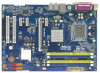
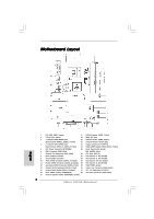
1 PS2_USB_PWR1 Jumper 17 USB 2.0 Header (USB6_7, Blue) 2 775-Pin CPU Socket 18 BIOS SPI Chip 3 2 x 240-pin DDR2 DIMM Slots 19 , Yellow) 5 ATX Power Connector (ATXPWR1) 23 Front Panel Audio Header 6 IDE1 Connector (IDE1, Blue) (HD_AUDIO1, Lime) 1, Purple) 2 ASRock P41C-DE Motherboard - ASRock P41C-DE | Quick Installation Guide - Page 3
accordance with the type of speaker you use. TABLE for Audio Output Connection Audio Output Channels Front Speaker Rear Speaker Central / Bass Side Speaker (No. 8) (No. 5) (No. 6) (No. 4) 2 V -- -- -- 4 V V -- -- 6 V V V -- 8 V V V V 3 ASRock P41C-DE Motherboard English - ASRock P41C-DE | Quick Installation Guide - Page 4
connect a front panel audio cable to the front panel audio header. After restarting your computer, you will find "VIA HD Audio Deck" tool on your system. Please follow below instructions according to the OS Multi-Streaming function or Side Speaker function. English 4 ASRock P41C-DE Motherboard - ASRock P41C-DE | Quick Installation Guide - Page 5
specific information about the model you are using. www.asrock.com/support/index.asp 1.1 Package Contents ASRock P41C-DE Motherboard (ATX Form Factor: 12.0-in x 8.4-in, 30.5 cm x 21.3 cm) ASRock P41C-DE Quick Installation Guide ASRock P41C-DE Support CD Two Serial ATA (SATA) Data Cables (Optional - ASRock P41C-DE | Quick Installation Guide - Page 6
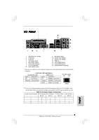
- 1 x PS/2 Mouse Port - 1 x PS/2 Keyboard Port - 1 x Parallel Port (ECP/EPP Support) - 1 x Serial Port: COM1 - 1 x Coaxial SPDIF Out Port - 1 x Optical SPDIF Out Port - 4 x Ready-to-Use USB 2.0 Ports - 1 x RJ-45 LAN Port with LED (ACT/LINK LED and SPEED LED) 6 ASRock P41C-DE Motherboard English - ASRock P41C-DE | Quick Installation Guide - Page 7
BIOS Feature Support CD Unique Feature Hardware Monitor OS Certifications - HD Audio Jack: Side Speaker/Rear Speaker/Central/Bass/ Line in/Front Speaker/Microphone (see CAUTION 7) - 4 x SATAII 3.0 Gb/s connectors (No Support / XP 64-bit compliant - FCC, CE, WHQL 7 ASRock P41C-DE Motherboard English - ASRock P41C-DE | Quick Installation Guide - Page 8
check page 38 of "User Manual" in the support CD. 3. This motherboard supports Untied Overclocking Technology. Please supports Dual Channel Memory Technology. Before you implement Dual Channel Memory Technology, make sure to read the installation guide . English 8 ASRock P41C-DE Motherboard - ASRock P41C-DE | Quick Installation Guide - Page 9
audio output, this motherboard supports 2-channel, 4-channel, 6-channel, and 8-channel modes. Please check the table on page 3 for proper connection. 8. Before installing SATAII hard disk to SATAII connector, please read the "SATAII Hard Disk Setup Guide" on page 28 of "User Manual" in the support - ASRock P41C-DE | Quick Installation Guide - Page 10
50% under 100 mA current consumption. For EuP ready power supply selection, we recommend you checking with the power supply manufacturer for more details. 10 ASRock P41C-DE Motherboard English - ASRock P41C-DE | Quick Installation Guide - Page 11
Before you insert the 775-LAND CPU into the socket, please check if the CPU surface is unclean or if there is any bent pin on the socket. Do not force to insert the CPU into the socket if above situation is found. Otherwise, the CPU will be seriously damaged. 11 ASRock P41C-DE Motherboard English - ASRock P41C-DE | Quick Installation Guide - Page 12
key notch Pin1 alignment key alignment key 775-LAND CPU 775-Pin Socket For proper inserting, please ensure to match support the load plate edge, engage PnP cap with right hand thumb and peel the cap from the socket while pressing on center of PnP cap to assist in removal. 12 ASRock P41C-DE - ASRock P41C-DE | Quick Installation Guide - Page 13
for after service. Step 4. Close the socket: Step 4-1. instruction manuals of your CPU fan and heatsink. Below is an example to illustrate the installation of the heatsink for 775-LAND CPU. Step 1. Apply thermal interface material onto center of IHS on the socket ASRock P41C-DE Motherboard English - ASRock P41C-DE | Quick Installation Guide - Page 14
Data Rate 2) DIMM slots and two 240-pin DDR3 (Double Data Rate 3) DIMM slots, and supports Dual Channel Memory Technology. For dual channel configuration, you always need to install identical (the same brand be installed on this motherboard at the same time. English 14 ASRock P41C-DE Motherboard - ASRock P41C-DE | Quick Installation Guide - Page 15
insert the DIMM into the slot until the retaining clips at both ends fully snap back in place and the DIMM is properly seated. 15 ASRock P41C-DE Motherboard English - ASRock P41C-DE | Quick Installation Guide - Page 16
with the slot and press firmly until the card is completely seated on the slot. Step 4. Fasten the card to the chassis with screws. 16 ASRock P41C-DE Motherboard English - ASRock P41C-DE | Quick Installation Guide - Page 17
CLRCMOS1 for 5 seconds. However, please do not clear the CMOS right after you update the BIOS. If you need to clear the CMOS when you just finish updating the BIOS, you must boot up the system first, and then shut it down before you do the clear-CMOS action. English 17 ASRock P41C-DE Motherboard - ASRock P41C-DE | Quick Installation Guide - Page 18
motherboard, you need to adjust the jumpers. Please follow the instructions below to set up the jumpers. Otherwise, the CPU and FSB1066 CPU, and try to overclock to FSB1333 (by BIOS setting) you may face the problem, that DRAM frequency will be overclocked very high. Please ASRock P41C-DE Motherboard - ASRock P41C-DE | Quick Installation Guide - Page 19
-conductor ATA 66/100 cable Note: Please refer to the instruction of your IDE device vendor for the details. Serial ATAII see p.2, No. 11) These four Serial ATAII (SATAII) connectors support SATA data cables for internal storage devices. The current SATAII interface ASRock P41C-DE Motherboard - ASRock P41C-DE | Quick Installation Guide - Page 20
cable that allows convenient connection and control of audio devices. 1. High Definition Audio supports Jack Sensing, but the panel wire on the chassis must support HDA to function correctly. Please follow the instruction in our manual and chassis manual to install your system. 2. If you use AC - ASRock P41C-DE | Quick Installation Guide - Page 21
and match the black wire to the ground pin. Though this motherboard provides 4-Pin CPU fan (Quiet Fan) support, the 3-Pin CPU fan still can work successfully even without the fan speed control function. If you plan do so will cause the failure to power up. 21 ASRock P41C-DE Motherboard English - ASRock P41C-DE | Quick Installation Guide - Page 22
Installation 8 4 HDMI_SPDIF Header (3-pin HDMI_SPDIF1) (see p.2 No. 22) HDMI_SPDIF header, providing SPDIF audio output to HDMI VGA card, allows the system to con nect HDMI Digital TV/ projector/LCD devices card. B. white end (2-pin) C. white end (3-pin) English 22 ASRock P41C-DE Motherboard - ASRock P41C-DE | Quick Installation Guide - Page 23
SATA / SATAII hard disk. 2.8 Driver Installation Guide To install the drivers to your system, please insert the support CD to your optical drive first. Then, the drivers compatible to your system can be auto risk before you apply Untied Overclocking Technology. English 23 ASRock P41C-DE Motherboard - ASRock P41C-DE | Quick Installation Guide - Page 24
press during the Power-On-Self-Test (POST) to enter BIOS Setup utility; otherwise, POST continues with its test routines. If you wish to enter BIOS Setup after POST, please restart the system by " from the BIN folder in the Support CD to display the menus. 24 ASRock P41C-DE Motherboard English - ASRock P41C-DE | Quick Installation Guide - Page 25
benötigen, besuchen Sie bitte unsere Webseite: www.asrock.com/support/index.asp 1.1 Kartoninhalt ASRock P41C-DE Motherboard (ATX-Formfaktor: 30.5 cm x 21.3 cm; 12.0 Zoll x 8.4 Zoll) ASRock P41C-DE Schnellinstallationsanleitung ASRock P41C-DE Support-CD Zwei Serial ATA (SATA) -Datenkabel (optional - ASRock P41C-DE | Quick Installation Guide - Page 26
Intel® G41 - Audio Codec) - PCIE x1 Gigabit LAN 10/100/1000 Mb/s - Atheros® AR8131L - Unterstützt Wake-On-LAN I/O Panel - 1 x PS/2-Mausanschluss - 1 x PS/2-Tastaturanschluss - 1 x Paralleler port: Unterstützung für ECP / EPP - 1 x Serieller port: COM 1 - 1 x Koaxial-SPDIF-Ausgang 26 ASRock P41C-DE - ASRock P41C-DE | Quick Installation Guide - Page 27
) - Sofortstart - ASRock Instant Flash (siehe VORSICHT 12) - ASRock OC DNA (siehe VORSICHT 13) - Hybrid Booster: - Schrittloser CPU-Frequenz-Kontrolle (siehe VORSICHT 14) - ASRock U-COP (siehe VORSICHT 15) - Boot Failure Guard (B.F.G. - Systemstartfehlerschutz) 27 ASRock P41C-DE Motherboard Deutsch - ASRock P41C-DE | Quick Installation Guide - Page 28
: http://www.asrock.com WARNUNG Beachten Sie bitte, dass Overclocking, einschließlich der Einstellung im BIOS, Anwenden der Threading Technology", finden Sie auf Seite 38 des auf der Support-CD enthaltenen Benutzerhandbuches beschrieben. 3. Dieses DDR2 533 28 ASRock P41C-DE Motherboard Deutsch - ASRock P41C-DE | Quick Installation Guide - Page 29
" auf der Support-CD, um Ihre des POST-Vorgangs oder durch Drücken der -Taste im BIOS-Setup-Menü Zugang zu ASRock Instant Flash. Sie brauchen dieses Werkzeug einfach nur zu starten und die neue BIOS-Datei auf Ihrem USB-Flash-Laufwerk, Diskettenlaufwerk oder der Festplatte zu 29 ASRock P41C-DE - ASRock P41C-DE | Quick Installation Guide - Page 30
speichern, und schon können Sie Ihr BIOS mit nur wenigen Klickvorgängen ohne Bereitstellung einer zusätzlichen Diskette oder eines anderen Wahl einer EuP-fähigen Stromversorgung empfehlen wir Ihnen, weitere Details beim Hersteller der Stromversorgung abzufragen. 30 ASRock P41C-DE Motherboard Deutsch - ASRock P41C-DE | Quick Installation Guide - Page 31
beinhalten das System-Passwort, Datum, Zeit und die verschiedenen BIOS-Parameter. Um die Systemparameter zu löschen und auf die Werkseinstellung des BIOS löschen müssen, müssen Sie zuerst das System starten und dann wieder ausschalten, bevor Sie den CMOS-Inhalt löschen. Deutsch 31 ASRock P41C-DE - ASRock P41C-DE | Quick Installation Guide - Page 32
oder FSB1066-CPU einsetzen und eine Übertaktung auf FSB1333 (per BIOS-Einstellung) versuchen, kann das Problem auftreten, dass die DRAM-Frequenz sehr stark übertaktet wird. Bitte . Bitte schauen Sie sich die nachstehenden Steckbrückeneinstellungen an. Deutsch 32 ASRock P41C-DE Motherboard - ASRock P41C-DE | Quick Installation Guide - Page 33
. Die aktuelle SATAII-Schnittstelle ermöglicht eine Datenübertragungsrate bis 3,0 Gb/s. Serial ATA- (SATA-) Datenkabel (Option) Sie können beide Enden des SATA-Datenkabels entweder mit der SATA / SATAIIFestplatte oder dem SATAII-Anschluss am Mainboard verbinden. 33 ASRock P41C-DE Motherboard - ASRock P41C-DE | Quick Installation Guide - Page 34
glichkeit und Kontrolle über Audio-Geräte. 1. High Definition Audio unterstützt Jack Sensing BIOS-Setup-Dienstprogramm auf. Wechseln Sie zu Erweiterte Einstellungen und wählen Sie Chipset-Konfiguration. Setzen Sie die Option Frontleistenkontrolle von [Automatisch] auf [Aktiviert]. 34 ASRock P41C-DE - ASRock P41C-DE | Quick Installation Guide - Page 35
werden. Um ein 20-pol. ATX-Netzteil zu verwenden, stecken Sie den Stecker mit Pin 1 und Pin 13 ein. Installation eines 20-pol. ATX-Netzteils 1 ASRock P41C-DE Motherboard 13 35 Deutsch - ASRock P41C-DE | Quick Installation Guide - Page 36
des HDMI_SPDIF-Kabels mit dem HDMI_SPDIF-Anschluss am Motherboard. Schließen Sie dann das weiße Ende (B oder C) des HDMI_SPDIF-Kabels an den HDMI_SPDIF-Anschluss der HDMI-VGA-Karte an. A. Schwarzes Ende B. Weißes Ende (zweipolig) C. Weißes Ende (dreipolig) Deutsch 36 ASRock P41C-DE Motherboard - ASRock P41C-DE | Quick Installation Guide - Page 37
der Support-CD, um die Menüs aufzurufen. Das Setup-Programm soll es Ihnen so leicht wie möglich machen. Es ist menügesteuert, d.h. Sie können in den verschiedenen Untermenüs Ihre Auswahl treffen und die Programme werden dann automatisch installiert. Deutsch 37 ASRock P41C-DE Motherboard - ASRock P41C-DE | Quick Installation Guide - Page 38
èle que vous utilisez. www.asrock.com/support/index.asp 1.1 Contenu du paquet Carte mère ASRock P41C-DE (Facteur de forme ATX: 12.0 pouces x 8.4 pouces, 30.5 cm x 21.3 cm) Guide d'installation rapide ASRock P41C-DE CD de soutien ASRock P41C-DE Deux câbles d'alimentation de série ATA (SATA) HDD (en - ASRock P41C-DE | Quick Installation Guide - Page 39
ère qualité CH Windows® VistaTM (codec audio VIA® VT1708S) - PCIE x1 Gigabit LAN 10/100/1000 Mb/s - Atheros® AR8131L - Support du Wake-On-LAN I/O Panel - 1 x port souris PS/2 - 1 x port clavier PS/2 - 1 x port parallèle: Support ECP/EPP - 1 x port série: COM 1 39 ASRock P41C-DE Motherboard Français - ASRock P41C-DE | Quick Installation Guide - Page 40
LED VITESSE) - Prise HD Audio: Haut-parleur latéral / Haut-parleur arrière / Central /Basses / Entrée Ligne / Haut-parleur frontal / Microphone (voir ATTENTION 7) - 4 x connecteurs SATAII, prennent en charge un taux de transfert de données pouvant aller jusqu'à 3.0Go/s (Ne supporte pas les fonctions - ASRock P41C-DE | Quick Installation Guide - Page 41
assurez-vous de bien lire le guide d'installation des modules mémoire en page 14 pour réaliser une installation correcte. 5. Veuillez vérifier dans le tableau ci-dessous pour les fréquences de prise en charge mémoire et les fréquences FSB UC correspondantes. Français 41 ASRock P41C-DE Motherboard - ASRock P41C-DE | Quick Installation Guide - Page 42
apporter des économies d'énergie exceptionnelles et d'améliorer l'efficacité énergétique sans sacrifier aux performances de calcul. Veuillez visiter notre site Web pour les procédures d'utilisation d'Intelligent Energy Saver. Site Web ASRock : http://www.asrock.com 42 ASRock P41C-DE Motherboard - ASRock P41C-DE | Quick Installation Guide - Page 43
®. Com este utilitário, poderá premir a tecla durante o teste de arranque POST ou premir a tecla para exibir o menu de configuração do BIOS para aceder ao ASRock Instant Flash. Execute esta ferramenta para guardar o novo ficheiro de BIOS numa unidade flash USB, numa disquete ou num disco - ASRock P41C-DE | Quick Installation Guide - Page 44
de suite après avoir mis le BIOS à jour. Si vous avez besoin d'effacer la CMOS lorsque vous avez fini de mettre le BIOS à jour, vous devez d'abord initialiser le système, puis le mettre hors tension avant de procéder à l'opération d'effacement de la CMOS. Français 44 ASRock P41C-DE Motherboard - ASRock P41C-DE | Quick Installation Guide - Page 45
vous avez besoin de régler les cavaliers. Veuillez suivre les instructions ci-dessous pour de l'overclocker en FSB1333 (via réglage du BIOS), vous pouvez faire face au problème, que la fréquence DRAM se retrouve overclockée de de cavaliers ci-dessous. Français 45 ASRock P41C-DE Motherboard - ASRock P41C-DE | Quick Installation Guide - Page 46
instructions du fabricant de des taux transferts de données pouvant aller jusqu'à 3,0 Go/s. Câble de données Série ATA (SATA) (en option) 46 L'une des deux extrémités du câble de données SATA peut être connectée au disque dur SATA / SATAIIou au connecteur SATAII sur la carte mère. ASRock P41C-DE - ASRock P41C-DE | Quick Installation Guide - Page 47
à OUT2_L. C. Connectez Ground (GND) à Ground (GND). D. MIC_RET et OUT_RET sont réservés au panneau audio HD. Vous n'avez pas besoin de les connecter pour le panneau audio AC'97. E. Entrer dans l'utilitaire de configuration du BIOS. Saisir les Paramètres avancés puis sélectionner Configuration du jeu - ASRock P41C-DE | Quick Installation Guide - Page 48
électrique ainsi qu'aux broches 1 et 13. 20-Installation de l'alimentation électrique ATX 1 13 Connecteur ATX 12V (ATX12V1 br. 8) (voir p.2 No. 31) 6 1 8 4 Veuillez connecter une unité d'alimentation électrique ATX 12V sur ce connecteur. Français 48 ASRock P41C-DE Motherboard - ASRock P41C-DE | Quick Installation Guide - Page 49
audio SPDIF vers la carte VGA HDMI, et permettant au système de se de la carte-mère. Connectez ensuite l'extrémité blanche (B ou C) du câble HDMI_SPDIF au connecteur HDMI_SPDIF de la carte VGA HDMI. B. extrémité blanche (2 briches) C. extrémité blanche (3 briches) Français 49 ASRock P41C-DE - ASRock P41C-DE | Quick Installation Guide - Page 50
de choisir parmi les choix prédéterminés. Pour des informations détaillées sur le BIOS, veuillez consulter le Guide de l'utilisateur (fichier PDF) dans le CD technique. 3. Informations sur le CD de support Cette carte mère supporte pour afficher les menus. 50 ASRock P41C-DE Motherboard Français - ASRock P41C-DE | Quick Installation Guide - Page 51
sul modello che si sta usando. www.asrock.com/support/index.asp 1.1 Contenuto della confezione Scheda madre ASRock P41C-DE (ATX Form Factor: 12.0-in x 8.4-in, 30.5 cm x 21.3 cm) Guida di installazione rapida ASRock P41C-DE CD di supporto ASRock P41C-DE Due cavi dati Serial ATA (SATA) (opzionali - ASRock P41C-DE | Quick Installation Guide - Page 52
Condensatore solido per alimentazione CPU Processore - LGA 775 per Intel® CoreTM 2 Extreme / CoreTM Northbridge: Intel® G41 - Southbridge: Intel x slot PCI Audio - 7.1 Audio HD CH Windows® VistaTM Premium Level (VIA® VT1708S Audio Codec) LAN SPDIF Out 52 ASRock P41C-DE Motherboard Italiano - ASRock P41C-DE | Quick Installation Guide - Page 53
(LED azione/collegamento e LED velocità) - Connettore HD Audio: cassa laterale / cassa posteriore / cassa centrale / ASRock U-COP (vedi ATTENZIONE 15) - Boot Failure Guard (B.F.G.) Monitor- - Sensore per la temperatura del processore aggio - Sensore temperatura scheda madre 53 ASRock P41C-DE - ASRock P41C-DE | Quick Installation Guide - Page 54
, come anche la regolazione delle impostazioni del BIOS, l'applicazione della tecnologia Untied Overclocking Technology, Tecnologia Hyper-Threading", per favore controllare pagina 38 del Manuale dell'utente all'interno del CD di supporto. sincronizzazione. 54 ASRock P41C-DE Motherboard Italiano - ASRock P41C-DE | Quick Installation Guide - Page 55
per l'uscita audio. Controllare la 28 del "Manuale utente" nel BIOS per accedere ad ASRock Instant Flash. Avviare questo strumento e salvare il nuovo file BIOS ASRock, fornisce un modo comodo per registrare le impostazioni OC e condividerle con gli altri. Aiuta 55 ASRock P41C-DE Motherboard Italiano - ASRock P41C-DE | Quick Installation Guide - Page 56
% con un consumo di corrente di 100 mA. Per la scelta di un'alimentatore predisposto EuP consigliamo di verificare ulteriori dettagli con il produttore. 56 ASRock P41C-DE Motherboard Italiano - ASRock P41C-DE | Quick Installation Guide - Page 57
jumper. Non cancellare la CMOS subito dopo aver aggiornato il BIOS. Se è necessario cancellare la CMOS una volta completato l'aggiornamento del BIOS, è necessario riavviare prima il sistema, e poi spegnerlo prima di procedere alla cancellazione della CMOS. Italiano 57 ASRock P41C-DE Motherboard - ASRock P41C-DE | Quick Installation Guide - Page 58
o una FSB1066 e si prova ad eseguire l'overcloccaggio a FSB1333 (con le impostazioni del BIOS) si possono avere problemi con la frequenza della DRAM che potrebbe essere overcloccata ad un valore riferimento alle impostazioni dei ponticelli riportate sotto. Italiano 58 ASRock P41C-DE Motherboard - ASRock P41C-DE | Quick Installation Guide - Page 59
p.2 Nr. 10) Questi quattro connettori Serial ATA (SATAII) supportano le periferiche di archiviazione HD SATA o SATAII per le funzioni di archiviazione interna. ATAII (SATAII) supportano cavi SATAII per hard disk SATA / SATAII o al connettore SATAII sulla scheda madre. 59 ASRock P41C-DE Motherboard - ASRock P41C-DE | Quick Installation Guide - Page 60
pannello audio HD. Non è necessario collegarli per il pannello audio AC'97. E. Entrare nel programma di impostazione BIOS. Entrare su Impostazioni avanzate, quindi selezionare Configurazione chipset. Impostare l'opzione Comando pannello anteriore da [Auto] a [Attivato]. Italiano 60 ASRock P41C-DE - ASRock P41C-DE | Quick Installation Guide - Page 61
un alimentatore ATX a 20 pin. Per usare l'alimentatore ATX a 20 pin, collegare l'alimentatore con il Pin 1 e il Pin 13. Installazione dell'alimentatore ATX a 20 pin 1 ASRock P41C-DE Motherboard 13 61 Italiano - ASRock P41C-DE | Quick Installation Guide - Page 62
p.2 Nr. 22) Installazione elettrica 4-Pin ATX 12V 8 4 Header HDMI_SPDIF, con uscita audio SPDIF su scheda HDMI VGA, consente al sistema di collegare dispositivi per TV digitale HDMI/ A. estremità nera B. estremità bianca (2 pin) C. estremità bianca (3 pin) Italiano 62 ASRock P41C-DE Motherboard - ASRock P41C-DE | Quick Installation Guide - Page 63
test di routine. Per entrare il BIOS Setup dopo il POST, riavvia il sistema premendo + + , o premi il tasto di reset sullo chassis del sistema. Per informazioni più dettagliate circa il Setup del BIOS, fare riferimento al Manuale contiene i driver e ASRock P41C-DE Motherboard - ASRock P41C-DE | Quick Installation Guide - Page 64
con el número de modelo específico de su placa. www.asrock.com/support/index.asp 1.1 Contenido de la caja Placa base ASRock P41C-DE (Factor forma ATX: 30,5 cm x 21,3 cm, 12,0" x 8,4") Guía de instalación rápida de ASRock P41C-DE CD de soporte de ASRock P41C-DE Dos cables de datos Serial ATA (SATA - ASRock P41C-DE | Quick Installation Guide - Page 65
10/100/1000 Mb/s - Atheros® AR8131L - Soporta Wake-On-LAN I/O Panel - 1 x puerto de ratón PS/2 - 1 x puerto de teclado PS/2 - 1 x puerto paralelo: soporta ECP/EPP - 1 x puerto serial: COM1 - 1 x puerto de salida coaxial SPDIF - 1 x puerto de salida óptica SPDIF 65 ASRock P41C-DE Motherboard Español - ASRock P41C-DE | Quick Installation Guide - Page 66
ÓN 10) - Administrador de energía inteligente (vea ATENCIÓN 11) - Instant Boot - ASRock Instant Flash (vea ATENCIÓN 12) - ASRock OC DNA (vea ATENCIÓN 13) - Amplificador Híbrido: - Stepless control de frecuencia de CPU (vea ATENCIÓN 14) - ASRock U-COP (vea ATENCIÓN 15) ASRock P41C-DE Motherboard - ASRock P41C-DE | Quick Installation Guide - Page 67
ía de Memoria de Doble Canal, asegúrese de leer la guía de instalación de módulos de memoria en la página 14 para su correcta instalación. 5. Compruebe la tabla siguiente para conocer la frecuencia de soporte de memoria y su frecuencia FSB CPU correspondiente. Español 67 ASRock P41C-DE Motherboard - ASRock P41C-DE | Quick Installation Guide - Page 68
un nivel de ahorro de energía excepcional y mejorar la eficiencia energética sin sacrificar el rendimiento del procesador. Visite nuestro sitio web para más información acerca del funcionamiento de Intelligent Energy Saver. Sitio web de ASRock: http://www.asrock.com Español 68 ASRock P41C-DE - ASRock P41C-DE | Quick Installation Guide - Page 69
de energía de 5v en modo de espera debería ser mayor del 50% con un consumo de corriente de 100mA. Para seleccionar una fuente de alimentación que cumpla la directiva EuP, le recomendamos que consulte con el fabricante de la fuente de alimentación para obtener más detalles. 69 ASRock P41C-DE - ASRock P41C-DE | Quick Installation Guide - Page 70
favor acuérdase de quitar el jumper cap después de limpiar el COMS. Si necesita borrar la CMOS cuando acabe de finalizar la actualización de la BIOS, debe arrancar primero el sistema y, a continuación, apagarlo antes de realizar la acción de borrado de CMOS. Español 70 ASRock P41C-DE Motherboard - ASRock P41C-DE | Quick Installation Guide - Page 71
FSB800 ó FSB1066, e intenta sobreacelerar a FSB1333 (por la configuración del BIOS) puede encontrarse con el problema de que la frecuencia DRAM quedará sobreacelerada muy alta. Por favor, use el placa base. Por favor, consulte las siguientes configuraciones de puente. 71 ASRock P41C-DE Motherboard - ASRock P41C-DE | Quick Installation Guide - Page 72
dispositivos de almacenamiento interno. La interfaz SATAII actual permite una velocidad de transferencia de 3.0 Gb/s. Cable de datos de serie ATA (SATA) (Opcional) Ambos extremos del cable pueden conectarse al disco duro SATA / SATAII o la conexión de la placa base. Español 72 ASRock P41C-DE - ASRock P41C-DE | Quick Installation Guide - Page 73
al panel de sonido AC'97. E. Entre en la Utilidad de configuración del BIOS Entre en Configuración avanzada y, a continuación, seleccione Configuración del conjunto de chips. En el panel de control frontal cambie la opción [Automático] a [Habilitado]. Español 73 ASRock P41C-DE Motherboard - ASRock P41C-DE | Quick Installation Guide - Page 74
si utiliza una fuente de alimentación ATX de 20 pins tradicional. Para usar una fuente de alimentación ATX de 20 pins, por favor, conecte su fuente de alimentación usando los Pins 1 y 13. Instalación de una Fuente de Alimentación ATX de 20 Pins 1 13 74 ASRock P41C-DE Motherboard Español - ASRock P41C-DE | Quick Installation Guide - Page 75
del cable HDMI_SPDIF en la cabecera HDMI_SPDIF de la placa base. Conecte después el extremo blanco (B o C) del cable HDMI_SPDIF en el conector HDMI_SPDIF de la tarjeta VGA HDMI. A. Extremo negro B. Extremo blanco (2 patillas) C. Extremo blanco (3 patillas) 75 ASRock P41C-DE Motherboard Español - ASRock P41C-DE | Quick Installation Guide - Page 76
. Para obtener información detalladas sobre la Utilidad de configuración de la BIOS, consulte el Manual del usuario (archivo PDF), que se encuentra en el CD de soporte. 3.Información de Software Support CD Esta placa-base soporta diversos tipos de sistema operativo Windows®: 7 / 7 64 bits / VistaTM - ASRock P41C-DE | Quick Installation Guide - Page 77
90 ASRock P41C-DE Motherboard - ASRock P41C-DE | Quick Installation Guide - Page 78
® ® / ® ® ® ® ® ® ® 91 ASRock P41C-DE Motherboard - ASRock P41C-DE | Quick Installation Guide - Page 79
® 92 ASRock P41C-DE Motherboard - ASRock P41C-DE | Quick Installation Guide - Page 80
" " ® ® 93 ASRock P41C-DE Motherboard - ASRock P41C-DE | Quick Installation Guide - Page 81
" " " " ® ® 94 ASRock P41C-DE Motherboard - ASRock P41C-DE | Quick Installation Guide - Page 82
"" "" "" "" 95 ASRock P41C-DE Motherboard - ASRock P41C-DE | Quick Installation Guide - Page 83
96 ASRock P41C-DE Motherboard - ASRock P41C-DE | Quick Installation Guide - Page 84
SATAII_1 SATAII_3 SATAII_2 SATAII_4 97 ASRock P41C-DE Motherboard - ASRock P41C-DE | Quick Installation Guide - Page 85
98 ASRock P41C-DE Motherboard - ASRock P41C-DE | Quick Installation Guide - Page 86
1 2 3 4 12 24 1 13 12 24 1 13 99 ASRock P41C-DE Motherboard - ASRock P41C-DE | Quick Installation Guide - Page 87
6 1 8 4 6 1 8 4 C B A 100 ASRock P41C-DE Motherboard - ASRock P41C-DE | Quick Installation Guide - Page 88
6 1 8 4 " " \\ " " ASRock P41C-DE Motherboard 101 - ASRock P41C-DE | Quick Installation Guide - Page 89
102 ASRock P41C-DE Motherboard - ASRock P41C-DE | Quick Installation Guide - Page 90
® ® ® ® ® ® ® ® ® ASRock P41C-DE Motherboard 103 - ASRock P41C-DE | Quick Installation Guide - Page 91
104 ASRock P41C-DE Motherboard - ASRock P41C-DE | Quick Installation Guide - Page 92
® ® " " ASRock P41C-DE Motherboard 105 - ASRock P41C-DE | Quick Installation Guide - Page 93
® ® TM TM ® ® ® ® 106 ASRock P41C-DE Motherboard - ASRock P41C-DE | Quick Installation Guide - Page 94
- ASRock P41C-DE Motherboard 107 - ASRock P41C-DE | Quick Installation Guide - Page 95
108 ASRock P41C-DE Motherboard - ASRock P41C-DE | Quick Installation Guide - Page 96
ASRock P41C-DE Motherboard 109 - ASRock P41C-DE | Quick Installation Guide - Page 97
110 SATAII_1 SATAII_3 SATAII_2 SATAII_4 ASRock P41C-DE Motherboard - ASRock P41C-DE | Quick Installation Guide - Page 98
ASRock P41C-DE Motherboard 111 - ASRock P41C-DE | Quick Installation Guide - Page 99
1 2 3 4 112 12 24 1 13 12 24 1 13 ASRock P41C-DE Motherboard - ASRock P41C-DE | Quick Installation Guide - Page 100
12 24 1 13 6 1 8 4 6 1 8 4 C B A ASRock P41C-DE Motherboard 113 - ASRock P41C-DE | Quick Installation Guide - Page 101
® ® TM TM 114 ASRock P41C-DE Motherboard - ASRock P41C-DE | Quick Installation Guide - Page 102
ASRock P41C-DE Motherboard 115 - ASRock P41C-DE | Quick Installation Guide - Page 103
® ® ® ® ® ® ® ® ® 116 ASRock P41C-DE Motherboard - ASRock P41C-DE | Quick Installation Guide - Page 104
® ® ASRock P41C-DE Motherboard 117 - ASRock P41C-DE | Quick Installation Guide - Page 105
® ® 118 ASRock P41C-DE Motherboard - ASRock P41C-DE | Quick Installation Guide - Page 106
® ® ® ® ASRock P41C-DE Motherboard 119 - ASRock P41C-DE | Quick Installation Guide - Page 107
120 ASRock P41C-DE Motherboard - ASRock P41C-DE | Quick Installation Guide - Page 108
ASRock P41C-DE Motherboard 121 - ASRock P41C-DE | Quick Installation Guide - Page 109
122 SATAII_1 SATAII_3 SATAII_2 SATAII_4 ASRock P41C-DE Motherboard - ASRock P41C-DE | Quick Installation Guide - Page 110
ASRock P41C-DE Motherboard 123 - ASRock P41C-DE | Quick Installation Guide - Page 111
1 2 3 4 124 12 24 1 13 12 24 1 13 ASRock P41C-DE Motherboard - ASRock P41C-DE | Quick Installation Guide - Page 112
12 24 1 13 6 1 8 4 6 1 8 4 C B A ASRock P41C-DE Motherboard 125 - ASRock P41C-DE | Quick Installation Guide - Page 113
® ® 126 ASRock P41C-DE Motherboard - ASRock P41C-DE | Quick Installation Guide - Page 114
X O O O X O O O O: X: O O O O ASRock P41C-DE Motherboard 127 - ASRock P41C-DE | Quick Installation Guide - Page 115
128 ASRock P41C-DE Motherboard - ASRock P41C-DE | Quick Installation Guide - Page 116
® ® ® ® ® ® ® ® ® ASRock P41C-DE Motherboard 129 - ASRock P41C-DE | Quick Installation Guide - Page 117
130 ASRock P41C-DE Motherboard - ASRock P41C-DE | Quick Installation Guide - Page 118
® ® ® ® ASRock P41C-DE Motherboard 131 - ASRock P41C-DE | Quick Installation Guide - Page 119
® ® ® 132 ® ASRock P41C-DE Motherboard - ASRock P41C-DE | Quick Installation Guide - Page 120
ASRock P41C-DE Motherboard 133 - ASRock P41C-DE | Quick Installation Guide - Page 121
134 ASRock P41C-DE Motherboard - ASRock P41C-DE | Quick Installation Guide - Page 122
SATAII_1 SATAII_3 SATAII_2 SATAII_4 ASRock P41C-DE Motherboard 135 - ASRock P41C-DE | Quick Installation Guide - Page 123
136 ASRock P41C-DE Motherboard - ASRock P41C-DE | Quick Installation Guide - Page 124
1 2 3 4 12 24 1 13 6 1 8 4 12 24 1 13 ASRock P41C-DE Motherboard 137 - ASRock P41C-DE | Quick Installation Guide - Page 125
6 1 8 4 C B A 138 ASRock P41C-DE Motherboard - ASRock P41C-DE | Quick Installation Guide - Page 126
6 1 8 4 ® ® ® ASRock P41C-DE Motherboard 139
-
 1
1 -
 2
2 -
 3
3 -
 4
4 -
 5
5 -
 6
6 -
 7
7 -
8
-
9
-
10
-
11
-
12
-
13
-
14
-
15
-
16
-
17
-
18
-
19
-
20
-
21
-
22
-
23
-
24
-
25
-
26
-
27
-
28
-
29
-
30
-
31
-
32
-
33
-
34
-
35
-
36
-
37
-
38
-
39
-
40
-
41
-
42
-
43
-
44
-
45
-
46
-
47
-
48
-
49
-
50
-
51
-
52
-
53
-
54
-
55
-
56
-
57
-
58
-
59
-
60
-
61
-
62
-
63
-
64
-
65
-
66
-
67
-
68
-
69
-
70
-
71
-
72
-
73
-
74
-
75
-
76
-
77
-
78
-
79
-
80
-
81
-
82
-
83
-
84
-
85
-
86
-
87
-
88
-
89
-
90
-
91
-
92
-
93
-
94
-
95
-
96
-
97
-
98
-
99
-
100
-
101
-
102
-
103
-
104
-
105
-
106
-
107
-
108
-
109
-
110
-
111
-
112
-
113
-
114
-
115
-
116
-
117
-
118
-
119
-
120
-
121
-
122
-
123
-
124
-
125
-
126
 |
 |
1
ASRock
P41C-DE
Motherboard
English
English
English
English
English
Copyright Notice:
Copyright Notice:
Copyright Notice:
Copyright Notice:
Copyright Notice:
No part of this installation guide may be reproduced, transcribed, transmitted, or trans-
lated in any language, in any form or by any means, except duplication of documen-
tation by the purchaser for backup purpose, without written consent of ASRock Inc.
Products and corporate names appearing in this guide may or may not be registered
trademarks or copyrights of their respective companies, and are used only for identifica-
tion or explanation and to the owners’ benefit, without intent to infringe.
Disclaimer:
Disclaimer:
Disclaimer:
Disclaimer:
Disclaimer:
Specifications and information contained in this guide are furnished for informational
use only and subject to change without notice, and should not be constructed as a
commitment by ASRock. ASRock assumes no responsibility for any errors or omissions
that may appear in this guide.
With respect to the contents of this guide, ASRock does not provide warranty of any kind,
either expressed or implied, including but not limited to the implied warranties or
conditions of merchantability or fitness for a particular purpose. In no event shall
ASRock, its directors, officers, employees, or agents be liable for any indirect, special,
incidental, or consequential damages (including damages for loss of profits, loss of
business, loss of data, interruption of business and the like), even if ASRock has been
advised of the possibility of such damages arising from any defect or error in the guide
or product.
This device complies with Part 15 of the FCC Rules. Operation is subject to the
following two conditions:
(1)
this device may not cause harmful interference, and
(2)
this device must accept any interference received, including interference that
may cause undesired operation.
Published October 2009
Copyright
©
2009 ASRock INC. All rights reserved.
CALIFORNIA, USA ONLY
The Lithium battery adopted on this motherboard contains Perchlorate, a toxic
substance controlled in Perchlorate Best Management Practices (BMP) regulations
passed by the California Legislature. When you discard the Lithium battery in
California, USA, please follow the related regulations in advance.
“Perchlorate Material-special handling may apply, see
www
.dtsc.ca.gov/hazardouswa
ste/perchlorate”
ASRock Website: http://www.asrock.com