ASRock P45DE User Manual
ASRock P45DE Manual
 |
View all ASRock P45DE manuals
Add to My Manuals
Save this manual to your list of manuals |
ASRock P45DE manual content summary:
- ASRock P45DE | User Manual - Page 1
P45DE User Manual Version 1.0 Published October 2008 Copyright©2008 ASRock INC. All rights reserved. 1 - ASRock P45DE | User Manual - Page 2
purchaser for backup purpose, without written consent of ASRock Inc. Products and corporate names appearing in this manual may or may not be registered trademarks or copyrights USA ONLY The Lithium battery adopted on this motherboard contains Perchlorate, a toxic substance controlled in Perchlorate - ASRock P45DE | User Manual - Page 3
Plug Feature and Operation Guide 29 2.14 Driver Installation Guide 31 2.15 Installing Windows® 2000 / XP / XP 64-bit / VistaTM / VistaTM 64-bit Without RAID Functions 31 2.15.1 Installing Windows® 2000 / XP / XP 64-bit Without RAID Functions 31 2.15.2 Installing Windows® VistaTM / VistaTM 64-bit - ASRock P45DE | User Manual - Page 4
51 3.6 Boot Screen 52 3.6.1 Boot Settings Configuration 52 3.7 Security Screen 53 3.8 Exit Screen 54 4 Software Support 55 4.1 Install Operating System 55 4.2 Support CD Information 55 4.2.1 Running Support CD 55 4.2.2 Drivers Menu 55 4.2.3 Utilities Menu 55 4.2.4 Contact Information 55 4 - ASRock P45DE | User Manual - Page 5
guide to BIOS setup and information of the Support CD. Because the motherboard specifications and the BIOS software might be updated, the content of this manual will be subject to change without notice. In case any modifications of this manual occur, the updated version will be available on ASRock - ASRock P45DE | User Manual - Page 6
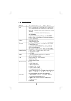
Compatible with FSB2000/1600/1333/1066/800 MHz (see CAUTION 1) - Supports Hyper-Threading Technology (see CAUTION 2) - Supports Untied Overclocking Technology (see CAUTION 3) - Supports EM64T CPU - Northbridge: Intel® P45 - Southbridge: Intel® ICH10 - Dual Channel DDR2 Memory Technology (see CAUTION - ASRock P45DE | User Manual - Page 7
Up Events - Supports Jumperfree - AMBIOS 2.3.1 Support - CPU, DRAM, NB, SB, VTT Voltage Multi-adjustment - Supports I. O. T. (Intelligent Overclocking Technology) - Supports Smart BIOS Support CD - Drivers, Utilities, AntiVirus Software (Trial Version) Unique Feature - ASRock OC Tuner (see - ASRock P45DE | User Manual - Page 8
system usage under Windows® XP and Windows® VistaTM. For Windows® XP 64-bit and Windows® VistaTM 64-bit with 64-bit CPU, there is no such limitation. 7. For microphone input, this motherboard supports both stereo and mono modes. For audio output, this motherboard supports 2-channel, 4- channel - ASRock P45DE | User Manual - Page 9
check if the CPU fan on the motherboard functions properly and unplug the power cord, then plug it back again. To improve heat dissipation, remember to spray thermal grease between the CPU and the heatsink when you install the PC system. 14. AHCI function is not supported under Windows® 2000 OS. It - ASRock P45DE | User Manual - Page 10
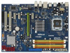
Motherboard Intel P45 Chipset LAN PHY Top: LINE IN Center: FRONT Bottom: MIC IN 35 PCIE1 34 PCI Express 2.0 33 AUDIO CODEC CD1 PCIE2 P45DE 15 1 ATX 12V Connector (ATX12V1) 2 775-Pin CPU Socket 3 North Bridge Controller 4 CPU Fan (PANEL1, Orange) 22 SPI BIOS Chip 23 Clear CMOS Jumper - ASRock P45DE | User Manual - Page 11
below for connection details in accordance with the type of speaker you use. TABLE for Audio Output Connection Audio Output Channels Front Speaker Rear Speaker Central / Bass Side Speaker (No. 7) (No. 4) (No. 5) (No. 3) 2 V -- -- -- 4 V V -- -- 6 V V V -- 8 V V V V 11 - ASRock P45DE | User Manual - Page 12
header. After restarting your computer, you will find "VIA HD Audio Deck" tool on your system. Please follow below instructions according to the OS you install. For Windows® 2000 / XP / XP 64-bit OS: Please click "VIA HD Audio Deck" icon , and click "Speaker". Then you are allowed to select - ASRock P45DE | User Manual - Page 13
Installation This is an ATX form factor (12.0" x 8.5", 30.5 x 21.6 cm) motherboard. Before you install the motherboard, study the configuration of your chassis to ensure that the motherboard fits into it. Make sure to unplug the power cord before installing or removing the motherboard. Failure to do - ASRock P45DE | User Manual - Page 14
For the installation of Intel 775-LAND CPU, please follow the steps below. 775-Pin Socket Overview Before you insert the 775-LAND CPU into the socket, please check if the CPU surface is unclean or if there is any bent pin on the socket. Do not force to insert the CPU into the socket - ASRock P45DE | User Manual - Page 15
CPU is within the socket and properly mated to the orient keys. Step 3. Remove PnP Cap (Pick and Place Cap): Use your left hand index finger and thumb to support PnP cap. 2. This cap must be placed if returning the motherboard for after service. Step 4. Close the socket: Step 4-1. Rotate the load - ASRock P45DE | User Manual - Page 16
Heatsink This motherboard is equipped with 775-Pin socket that supports Intel 775-LAND CPU. Please adopt the type of heatsink and cooling fan compliant with Intel 775-LAND CPU to dissipate heat. Before you installed the heatsink, you need to spray thermal interface material between the CPU and the - ASRock P45DE | User Manual - Page 17
2.5 Installation of Memory Modules (DIMM) This motherboard provides four 240-pin DDR2 (Double Data Rate 2) DIMM slots, and supports Dual Channel Memory Technology. For dual channel configuration, you always need to install identical (the same brand, speed, size and chip-type) DDR2 DIMM pair - ASRock P45DE | User Manual - Page 18
matches the break on the slot. notch break notch break The DIMM only fits in one correct orientation. It will cause permanent damage to the motherboard and the DIMM if you force the DIMM into the slot at incorrect orientation. Step 3. Firmly insert the DIMM into the slot until the retaining - ASRock P45DE | User Manual - Page 19
the expansion card and make necessary hardware settings for the card before you start the installation. Step 2. Remove the system unit cover (if your motherboard is already installed in a chassis). Step 3. Remove the bracket facing the slot that you intend to use. Keep the screws for later use. Step - ASRock P45DE | User Manual - Page 20
short pin2 and pin3 on CLRCMOS1 for 5 seconds. However, please do not clear the CMOS right after you update the BIOS. If you need to clear the CMOS when you just finish updating the BIOS, you must boot up the system first, and then shut it down before you do the clearCMOS action. 20 - ASRock P45DE | User Manual - Page 21
to the motherboard connect the black end to the IDE devices 80-conductor ATA 66/100/133 cable Note: Please refer to the instruction of your 4) SATAII_6 (Port 5) These six Serial ATAII (SATAII) connectors support SATA data cables for internal storage devices. The current SATAII interface allows - ASRock P45DE | User Manual - Page 22
panel, there are three USB 2.0 headers on this motherboard. Each USB 2.0 header can support two USB 2.0 ports. This header supports an optional wireless transmitting and receiving infrared module. This connector allows you to receive stereo audio input from sound sources such as a CD-ROM, DVD-ROM - ASRock P45DE | User Manual - Page 23
audio devices. 1. High Definition Audio supports Jack Sensing, but the panel wire on the chassis must support HDA to function correctly. Please follow the instruction in our manual and chassis manual for HD audio panel only. You don't need to connect them for AC'97 audio panel. E. Enter BIOS Setup - ASRock P45DE | User Manual - Page 24
fan (Quiet Fan) support, the 3-Pin CPU fan still can work successfully even without the fan speed control function. If you plan to connect the 3-Pin CPU fan to the CPU fan connector on this motherboard, please connect it to Pin 1-3. Pin 1-3 Connected 3-Pin Fan Installation ATX Power Connector (24 - ASRock P45DE | User Manual - Page 25
5V HDMI_SPDIF Cable (Optional) C B A HDMI_SPDIF header, providing SPDIF audio output to HDMI VGA card, allows the system to connect HDMI Digital connect the black end (A) of HDMI_SPDIF cable to the HDMI_SPDIF header on the motherboard. Then connect the white end (B or C) of HDMI_SPDIF cable to the - ASRock P45DE | User Manual - Page 26
25. For the pin definition of HDMI_SPDIF connectors on HDMI VGA card, please refer to the user manual of HDMI VGA card vendor. Incorrect connection may cause permanent damage to this motherboard and the HDMI VGA card. Step 3. Connect the white end (B or C) of HDMI_SPDIF cable to the HDMI_SPDIF - ASRock P45DE | User Manual - Page 27
guide. Some default setting of SATAII hard disks may not be at SATAII mode, which operate with the best performance. In order to enable SATAII function, please follow the below instruction website for details: http://www.hitachigst.com/hdd/support/download.htm The above examples are just for your - ASRock P45DE | User Manual - Page 28
Serial ATAII (SATAII) Hard Disks Installation P45DE adopts Intel® ICH10 south bridge chipset that supports Serial ATA (SATA) / Serial ATAII (SATAII) hard disks. You may install SATA / SATAII hard disks on this motherboard for internal storage devices. This section will guide you to install the SATA - ASRock P45DE | User Manual - Page 29
is installed into system properly. The latest SATA / SATAII driver is available on our support website: www.asrock.com 4. Make sure to use the SATA power cable & data cable, which are from our motherboard package. 5. Please follow below instructions step by step to reduce the risk of HDD crash or - ASRock P45DE | User Manual - Page 30
cable to (White) to the power supply 1x4-pin cable. the motherboard's SATAII connector. SATA power cable 1x4-pin power connector (White) Step attention, before you process the Hot Unplug: Please do follow below instruction sequence to process the Hot Unplug, improper procedure will cause the SATA - ASRock P45DE | User Manual - Page 31
procedures according to the OS you install. Since Windows® 2000 AHCI driver is not provided by the chipset vendor, AHCI function is not supported under Windows® 2000. 2.15.1 Installing Windows® 2000 / XP / XP 64-bit Without RAID Functions If you want to install Windows® 2000 / XP / XP 64-bit OS on - ASRock P45DE | User Manual - Page 32
the instruction to install Windows® VistaTM / VistaTM 64-bit OS on your system. When you see "Where do you want to install Windows?" page, please insert the ASRock Support CD into your optical drive, and click the "Load Driver" button on the left on the bottom to load the Intel® AHCI drivers. Intel - ASRock P45DE | User Manual - Page 33
Technology This motherboard supports Untied Overclocking Technology, which means during overclocking, FSB enjoys better margin due to fixed PCI / PCIE buses. Before you enable Untied Overclocking function, please enter "Overclock Mode" option of BIOS setup to set the selection from [Auto] to [Manual - ASRock P45DE | User Manual - Page 34
BIOS FWH chip on the motherboard stores the BIOS SETUP UTILITY. You may run the BIOS SETUP UTILITY when you start up the computer. Please press during the Power-On-Self-Test (POST) to enter the BIOS on. Because the BIOS software is constantly being updated, the following BIOS setup screens and - ASRock P45DE | User Manual - Page 35
Overview System Time System Date [14:00:09] [Mon 10/06/2008] BIOS Version : P45DE P1.00 Processor Type : Intel (R) Core(TM)2 Duo CPU E6750 @ 2.66GHz (64bit) Processor Speed : 2666MHz Microcode Update : 6FB/B6 Cache Size : 4096KB Total Memory DDRII_A1 DDRII_A2 DDRII_B1 DDRII_B2 : 4096MB - ASRock P45DE | User Manual - Page 36
will pop-out the following message, "Save configuration changes and exit setup?" Select [OK] to save the changes and exit the BIOS SETUP UTILITY. Load BIOS Defaults Load BIOS default values for all the setup questions. F9 key can be used for this operation. Load Performance Setup Default (IDE/SATA - ASRock P45DE | User Manual - Page 37
to malfunction. 3.4.1Overclock Configuration BIOS SETUP UTILITY Advanced Overclock Settings Ratio Actual Value Ratio CMOS Setting Intel (R) SpeedStep(tm) tech. Overclock Mode CPU Frequency (MHZ) PCIE Frequency is a read-only item, which displays the ratio actual value of this motherboard. 37 - ASRock P45DE | User Manual - Page 38
the ratio value of this motherboard. Intel (R) SpeedStep(tm) tech. Intel (R) SpeedStep(tm) tech. is Intel's new power saving technology. install Windows® VistaTM and want to enable this function, please set this item to [Enabled]. This item will be hidden if the current CPU does not support Intel - ASRock P45DE | User Manual - Page 39
Voltage Use this to select CPU Voltage. Configuration options: [Auto] and [Manual]. The default value of this feature is [Auto]. DRAM Voltage : 1.96 V DRAM Voltage Use this to select DRAM Voltage. Configuration options: [Auto], [1.79V], [1.85V], [1.90V], [1. - ASRock P45DE | User Manual - Page 40
3.4.2CPU Configuration BIOS SETUP UTILITY Advanced CPU Configuration Overclock Mode CPU Frequency (MHz) PCIE Frequency (MHz) Boot Failure Guard Spread Spectrum Ratio Actual Value Ratio CMOS Setting Enhanced Halt State Intel (R) Virtualization tech. CPU Thermal Throttling No-Excute Memory Protection - ASRock P45DE | User Manual - Page 41
Schemes" as "Portable/Laptop" to enable this function. If you install Windows® VistaTM and want to enable this function, please set this item to [Enabled]. This item will be hidden if the current CPU does not support Intel (R) SpeedStep(tm) tech.. Please note that enabling this function may reduce - ASRock P45DE | User Manual - Page 42
]. The default value is [Disabled]. 3.4.3Chipset Configuration BIOS SETUP UTILITY Advanced Chipset Settings Memory Remap Feature [Disabled on the CPU and memory module you adopt on this motherboard. Please refer to page 8 for the CPU FSB frequency and its corresponding memory support frequency. - ASRock P45DE | User Manual - Page 43
DRAM tRCD This controls the number of DRAM clocks for TRCD. Configuration options: Configuration options: [Auto], [3] to [10]. DRAM tWR This controls the number of DRAM clocks for TWR. Configuration options: Configuration options: [Auto], [3] to [15]. DRAM tRFC This controls the number of DRAM - ASRock P45DE | User Manual - Page 44
HD Audio will be disabled when PCI Sound Card is plugged. Front Panel Select [Auto], [Enabled] or [Disabled] for the onboard HD Audio Front Panel. CD-In Use this item to enable or disable CD-In of OnBoard HD Audio. If you plan to use this motherboard to submit Windows® VistaTM logo test, please - ASRock P45DE | User Manual - Page 45
3.4.4ACPI Configuration BIOS SETUP UTILITY Advanced ACPI Configuration Suspend To RAM Repost to auto-detect or disable the Suspend-toRAM feature. Select [Auto] will enable this feature if the OS supports it. If you set this item to [Disabled], the function "Repost Video on STR Resume" will be - ASRock P45DE | User Manual - Page 46
you plan to use this motherboard to submit Windows® VistaTM certification. 3.4.5IDE Configuration BIOS SETUP UTILITY Advanced IDE Windows environment if this option is enabled. Configuration options: [Enabled] and [Disabled]. AHCI (Advanced Host Controller Interface) supports instruction. 46 - ASRock P45DE | User Manual - Page 47
BIOS SETUP UTILITY Advanced Primary IDE Master Device Vendor Size LBA Mode Block Mode PIO Mode Async DMA Ultra DMA S.M.A.R.T. Type LBA/Large Mode Block (Multi-Sector Transfer) PIO Mode DMA Mode S.M.A.R.T. 32Bit Data Transfer :Hard Disk :ST340014A :40.0 GB :Supported 512 MB under DOS and Windows; - ASRock P45DE | User Manual - Page 48
Enabled]. 32-Bit Data Transfer Use this item to enable 32-bit access to maximize the IDE hard disk data transfer rate. 3.4.6PCIPnP Configuration BIOS SETUP UTILITY Advanced Advanced PCI / PnP Settings PCI Latency Timer PCI IDE BusMaster [32] [Enabled] Value in units of PCI clocks for PCI device - ASRock P45DE | User Manual - Page 49
3.4.7Floppy Configuration In this section, you may configure the type of your floppy drive. BIOS SETUP UTILITY Advanced Floppy Configuration Floppy A [1.44 MB 312"] Select the type of floppy drive connected to the system. +F1 F9 F10 ESC Select Screen Select Item Change Option General Help Load - ASRock P45DE | User Manual - Page 50
this item to enable or disable the USB 2.0 support. Legacy USB Support Use this option to select legacy support for USB devices. There are four configuration options: [Enabled], [Auto], [Disabled] and [BIOS Setup Only]. The default value is [BIOS Setup Only]. Please refer to below descriptions for - ASRock P45DE | User Manual - Page 51
you to monitor the status of the hardware on your system, including the parameters of the CPU temperature, motherboard temperature, CPU fan speed, chassis fan speed, and the critical voltage. BIOS SETUP UTILITY Main Smart Advanced H/W Monitor Boot Security Exit Hardware Health Event Monitoring - ASRock P45DE | User Manual - Page 52
this section, it will display the available devices on your system for you to configure the boot settings and the boot priority. BIOS SETUP UTILITY Main Smart Advanced H/W Monitor Boot Security Exit Boot Settings Boot Settings Configuration Configure Settings during System Boot. 1st Boot Device - ASRock P45DE | User Manual - Page 53
"Full Screen Logo". Configuration options: [Auto], [PCIE2.0 Revolution], [Scenery] and [ASRock]. The default value is [Auto]. Currently, the option [Auto] is set to system. For the user password, you may also clear it. BIOS SETUP UTILITY Main Smart Advanced H/W Monitor Boot Security Exit Security - ASRock P45DE | User Manual - Page 54
and exit setup?" Select [OK] to save the changes and exit the BIOS SETUP UTILITY. Discard Changes and Exit When you select this option, it message, "Discard changes and exit setup?" Select [OK] to exit the BIOS SETUP UTILITY without saving any changes. Discard Changes When you select this option - ASRock P45DE | User Manual - Page 55
install the necessary drivers to activate the devices. 4.2.3 Utilities Menu The Utilities Menu shows the applications software that the motherboard supports. Click on a specific item then follow the installation wizard to install it. 4.2.4 Contact Information If you need to contact ASRock or want to
-
 1
1 -
 2
2 -
 3
3 -
 4
4 -
 5
5 -
 6
6 -
 7
7 -
8
-
9
-
10
-
11
-
12
-
13
-
14
-
15
-
16
-
17
-
18
-
19
-
20
-
21
-
22
-
23
-
24
-
25
-
26
-
27
-
28
-
29
-
30
-
31
-
32
-
33
-
34
-
35
-
36
-
37
-
38
-
39
-
40
-
41
-
42
-
43
-
44
-
45
-
46
-
47
-
48
-
49
-
50
-
51
-
52
-
53
-
54
-
55
 |
 |

1
P45DE
User Manual
Version 1.0
Published October 2008
Copyright©2008 ASRock INC. All rights reserved.