ASRock P45DE Quick Installation Guide
ASRock P45DE Manual
 |
View all ASRock P45DE manuals
Add to My Manuals
Save this manual to your list of manuals |
ASRock P45DE manual content summary:
- ASRock P45DE | Quick Installation Guide - Page 1
for backup purpose, without written consent of ASRock Inc. Products and corporate names appearing in this guide may or may not be registered trademarks or ASRock Website: http://www.asrock.com Published October 2008 Copyright©2008 ASRock INC. All rights reserved. 1 ASRock P45DE Motherboard English - ASRock P45DE | Quick Installation Guide - Page 2
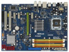
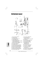
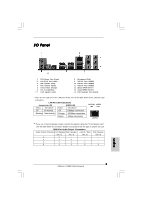
(PCI1 - 2) 29 USB 2.0 Header (USB/WIFI, Blue) 30 PCI Express x1 Slot (PCIE4) 31 PCI Express x1 Slot (PCIE3) 32 Front Panel Audio Header (HD_AUDIO1, Lime) 33 PCI Express 2.0 x16 Slot (PCIE2, Green) 34 Internal Audio Connector: CD1 (Black) 35 PCI Express x1 Slot (PCIE1) 2 ASRock P45DE Motherboard - ASRock P45DE | Quick Installation Guide - Page 3
in accordance with the type of speaker you use. TABLE for Audio Output Connection Audio Output Channels Front Speaker Rear Speaker Central / Bass Side Speaker (No. 7) (No. 4) (No. 5) (No. 3) 2 V -- -- -- 4 V V -- -- 6 V V V -- 8 V V V V 3 ASRock P45DE Motherboard English - ASRock P45DE | Quick Installation Guide - Page 4
will find "VIA HD Audio Deck" tool on your system. Please follow below instructions according to the OS you install. For Windows® 2000 / XP / XP 64-bit OS: Please click "VIA HD Audio Deck" icon , and either Multi-Streaming function or Side Speaker function. English 4 ASRock P45DE Motherboard - ASRock P45DE | Quick Installation Guide - Page 5
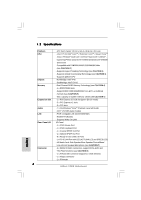
for specific information about the model you are using. www.asrock.com/support/index.asp 1.1 Package Contents ASRock P45DE Motherboard (ATX Form Factor: 12.0-in x 8.5-in, 30.5 cm x 21.6 cm) ASRock P45DE Quick Installation Guide ASRock P45DE Support CD One 80-conductor Ultra ATA 66/100/133 IDE - ASRock P45DE | Quick Installation Guide - Page 6
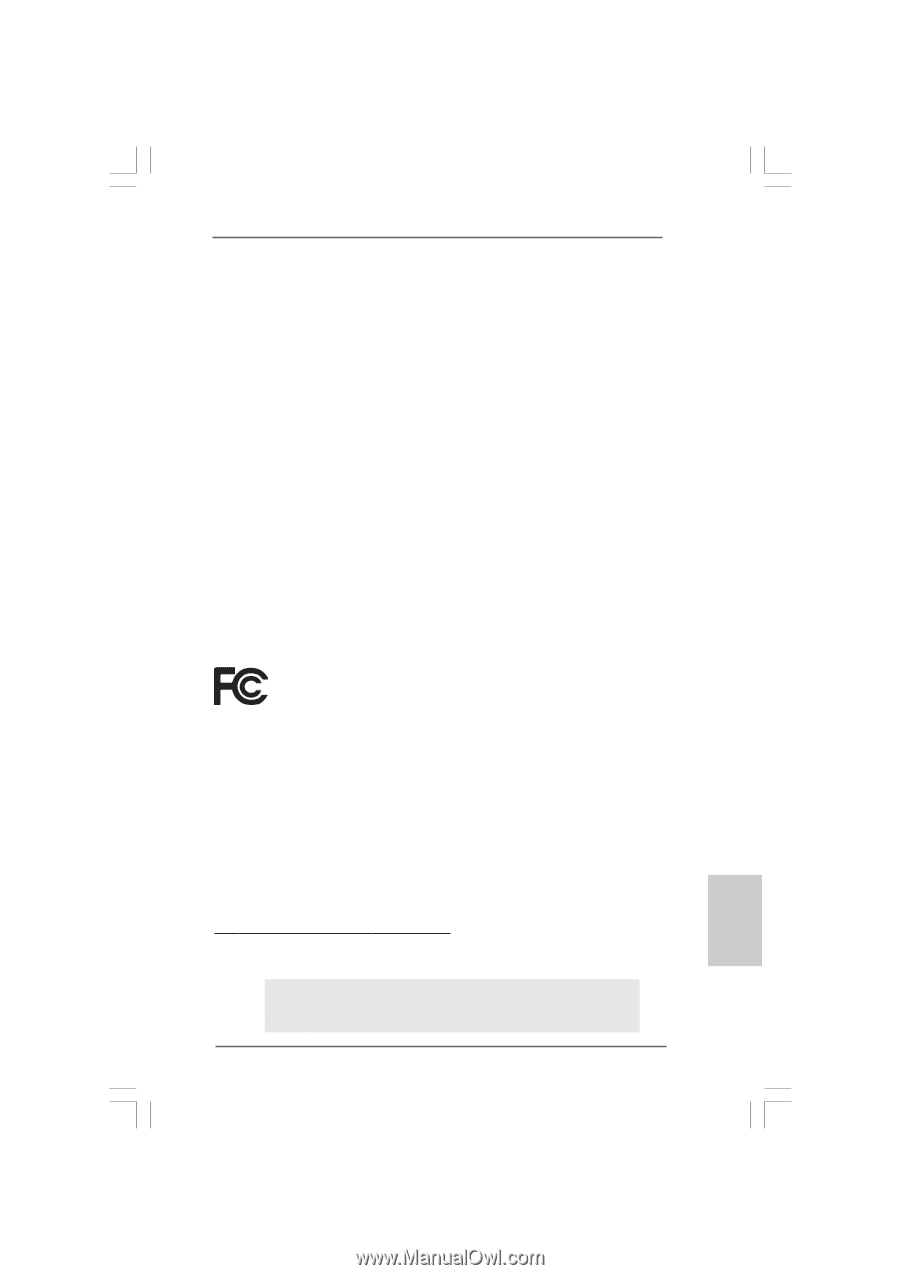
Compatible with FSB2000/1600/1333/1066/800 MHz (see CAUTION 1) - Supports Hyper-Threading Technology (see CAUTION 2) - Supports Untied Overclocking Technology (see CAUTION 3) - Supports EM64T CPU - Northbridge: Intel® P45 - Southbridge: Intel® ICH10 - Dual Channel DDR2 Memory Technology (see CAUTION - ASRock P45DE | Quick Installation Guide - Page 7
Up Events - Supports Jumperfree - AMBIOS 2.3.1 Support - CPU, DRAM, NB, SB, VTT Voltage Multi-adjustment - Supports I. O. T. (Intelligent Overclocking Technology) - Supports Smart BIOS Support CD - Drivers, Utilities, AntiVirus Software (Trial Version) Unique Feature - ASRock OC Tuner (see - ASRock P45DE | Quick Installation Guide - Page 8
surveil your system by hardware monitor function and overclock your hardware devices to get the best system performance under Windows® environment. Please visit our website for the operation procedures of ASRock OC Tuner. ASRock website: http://www.asrock.com English 8 ASRock P45DE Motherboard - ASRock P45DE | Quick Installation Guide - Page 9
grease between the CPU and the heatsink when you install the PC system. 14. AHCI function is not supported under Windows® 2000 OS. It is recommended to use IDE mode under Windows® 2000. Please refer to page 46 of "User Manual" in the support CD for detailed setup. 9 ASRock P45DE Motherboard English - ASRock P45DE | Quick Installation Guide - Page 10
Before you insert the 775-LAND CPU into the socket, please check if the CPU surface is unclean or if there is any bent pin on the socket. Do not force to insert the CPU into the socket if above situation is found. Otherwise, the CPU will be seriously damaged. 10 ASRock P45DE Motherboard English - ASRock P45DE | Quick Installation Guide - Page 11
orient keys. Step 3. Remove PnP Cap (Pick and Place Cap): Use your left hand index finger and thumb to support the load plate edge, engage PnP cap with right hand thumb and peel the cap from the socket while pressing on center of PnP cap to assist in removal. 11 ASRock P45DE Motherboard English - ASRock P45DE | Quick Installation Guide - Page 12
clockwise, the heatsink cannot be secured on the motherboard. Step 5. Step 6. Connect fan header with the CPU fan connector on the motherboard. Secure excess cable with tie-wrap to ensure cable does not interfere with fan operation or contact other components. 12 ASRock P45DE Motherboard English - ASRock P45DE | Quick Installation Guide - Page 13
Installation of Memory Modules (DIMM) This motherboard provides four 240-pin DDR2 (Double Data Rate 2) DIMM slots, and supports Dual Channel Memory Technology. For dual channel memory module into DDR2 slot; otherwise, this motherboard and DIMM may be damaged. English 13 ASRock P45DE Motherboard - ASRock P45DE | Quick Installation Guide - Page 14
notch on the DIMM matches the break on the slot. The DIMM only fits in one correct orientation. It will cause permanent damage to the motherboard and the DIMM if you force the DIMM into the slot at incorrect orientation. Step 3. Firmly insert the DIMM into the slot until the retaining - ASRock P45DE | Quick Installation Guide - Page 15
for the card before you start the installation. Step 2. Remove the system unit cover (if your motherboard is already installed in a chassis). Step 3. Remove the bracket facing the slot that you intend to the chassis with screws. Step 6. Replace the system cover. 15 ASRock P45DE Motherboard English - ASRock P45DE | Quick Installation Guide - Page 16
on CLRCMOS1 for 5 seconds. However, please do not clear the CMOS right after you update the BIOS. If you need to clear the CMOS when you just finish updating the BIOS, you must boot up the system first, and then shut it down before you do the clearCMOS action. English 16 ASRock P45DE Motherboard - ASRock P45DE | Quick Installation Guide - Page 17
motherboard connect the black end to the IDE devices 80-conductor ATA 66/100/133 cable Note: Please refer to the instruction (Port 5) These six Serial ATAII (SATAII) connectors support SATA data cables for internal storage devices. The current motherboard. 17 ASRock P45DE Motherboard English - ASRock P45DE | Quick Installation Guide - Page 18
Connectors (4-pin CD1) (see p.2 No. 34) CD1 This header supports an optional wireless transmitting and receiving infrared module. This connector allows you to receive stereo audio input from sound sources such as a CD-ROM, DVD-ROM, TV tuner card, or MPEG card. English 18 ASRock P45DE Motherboard - ASRock P45DE | Quick Installation Guide - Page 19
cable that allows convenient connection and control of audio devices. 1. High Definition Audio supports Jack Sensing, but the panel wire on the chassis must support HDA to function correctly. Please follow the instruction in our manual and chassis manual to install your system. 2. If you use AC - ASRock P45DE | Quick Installation Guide - Page 20
5 1 12V power supply. To use the 4-pin ATX power supply, please plug your power supply along with Pin 1 and Pin 5. 4-Pin ATX 12V Power Supply Installation 8 4 Serial port Header (9-pin COM1) (see p.2 No. 24) This COM1 header supports a serial port module. English 20 ASRock P45DE Motherboard - ASRock P45DE | Quick Installation Guide - Page 21
Cable (Optional) A. black end C B A HDMI_SPDIF header, providing SPDIF audio output to HDMI VGA card, allows the system to con nect HDMI Digital the black end (A) of HDMI_SPDIF cable to the HDMI_SPDIF header on the motherboard. Then connect the white end (B or C) of HDMI_SPDIF cable to the - ASRock P45DE | Quick Installation Guide - Page 22
up BIOS. A. Enter BIOS SETUP UTILITY Advanced screen IDE Configuration. B. Set "SATAII Configuration" to [Enhanced], and then in the option "Configure SATAII as", please set the option to [IDE]. STEP 2: Install Windows® VistaTM / VistaTM 64-bit OS on your system. 22 ASRock P45DE Motherboard English - ASRock P45DE | Quick Installation Guide - Page 23
the instruction to install Windows® VistaTM / VistaTM 64-bit OS on your system. When you see "Where do you want to install Windows?" page, please insert the ASRock Support CD into your optical drive, and click the "Load Driver" button on the left on the bottom to load the Intel® AHCI drivers. Intel - ASRock P45DE | Quick Installation Guide - Page 24
PDF file) contained in the Support CD. 4. Software Support CD information This motherboard supports various Microsoft® Windows® operating systems: 2000 / XP / XP 64-bit / VistaTM / VistaTM 64-bit. The Support CD that came with the motherboard contains necessary drivers and useful utilities that will - ASRock P45DE | Quick Installation Guide - Page 25
Ihrem Modell benötigen, besuchen Sie bitte unsere Webseite: www.asrock.com/support/index.asp 1.1 Kartoninhalt ASRock P45DE Motherboard (ATX-Formfaktor: 30.5 cm x 21.6 cm; 12.0 Zoll x 8.5 Zoll) ASRock P45DE Schnellinstallationsanleitung ASRock P45DE Support-CD Ein 80-adriges Ultra-ATA 66/100/133 IDE - ASRock P45DE | Quick Installation Guide - Page 26
CPU Chipsatz Speicher Erweiterungssteckplätze Audio LAN E/A-Anschlüsse an der Rückseite Anschlüsse 26 - ATX-Formfaktor: 30.5 cm x 21.6 cm; 12.0 Zoll x 8.5 Zoll - LGA 775 für Intel® GB/s-Anschlüsse, unterstützen NCQ, AHCI und "Hot Plug" Funktionen (siehe VORSICHT 8) ASRock P45DE Motherboard Deutsch - ASRock P45DE | Quick Installation Guide - Page 27
Vcore Betriebssysteme - Unterstützt Microsoft® Windows® 2000 / XP / XP 64-Bit / VistaTM / VistaTM 64-Bit (siehe VORSICHT 14) Zertifizierungen - FCC, CE, WHQL * Für die ausführliche Produktinformation, besuchen Sie bitte unsere Website: http://www.asrock.com Deutsch 27 ASRock P45DE Motherboard - ASRock P45DE | Quick Installation Guide - Page 28
lesen Sie bitte "Setup-Anleitung für SATAII-Festplatte" auf Seite 27 der "Bedienungsanleitung" auf der Support-CD, um Ihre SATAII-Festplatte dem SATAII-Modus anzugleichen. Sie können die SATA-Festplatte auch direkt mit dem SATAII-Anschluss verbinden. Deutsch 28 ASRock P45DE Motherboard - ASRock P45DE | Quick Installation Guide - Page 29
://www.asrock.com 12. Obwohl dieses Motherboard stufenlose Steuerung bietet, wird Overclocking nicht empfohlen. Frequenzen, die über den für den jeweiligen Prozessor vorgesehenen liegen, können das System instabil werden lassen oder die CPU beschädigen. 13. Wird eine Überhitzung der CPU registriert - ASRock P45DE | Quick Installation Guide - Page 30
(Sockel) 775-Pin Sockel Übersicht Bevor Sie die 775-Pin CPU in den Sockel sitzen, prüfen Sie bitte, ob die CPU-Oberfläche sauber ist und keine der Kontakte verbogen sind. Setzen Sie die CPU nicht mit Gewalt in den Sockel, dies kann die CPU schwer beschädigen. Deutsch 30 ASRock P45DE Motherboard - ASRock P45DE | Quick Installation Guide - Page 31
775-Pin Sockel 775-Pin CPU Um die CPU ordnungsgemäß einsetzen zu können, richten Sie die zwei Orientierungskerben der CPU mit den beiden Markierungen des Sockels aus. Schritt 2-3. Drücken Sie die CPU vorsichtig in vertikaler Richtung in den Sockel. 31 ASRock P45DE Motherboard Deutsch - ASRock P45DE | Quick Installation Guide - Page 32
Schritt 2-4. Prüfen Sie, dass die CPU ordnungsgemäß im Sockel sitzt und die Orientierungskerben einwandfrei in den entsprechenden Auskerbungen sitzen. Schritt ßen Sie den Ladehebel. Schritt 4-3. Sichern Sie Ladehebel und Ladeplatte mithilfe des Hebelverschlusses. 32 ASRock P45DE Motherboard Deutsch - ASRock P45DE | Quick Installation Guide - Page 33
örper nicht ordnungsgemäß am Motherboard befestigt. Schritt 5. Schließen Sie den Lüfter an den CPULüfteranschluss des Motherboards. Schritt 6. Befestigen Sie überschüssiges Kabel mit Band, um eine Störung des Lüfters oder Kontakt mit anderen Teilen zu vermeiden. Deutsch 33 ASRock P45DE Motherboard - ASRock P45DE | Quick Installation Guide - Page 34
2.3 Installation der Speichermodule (DIMM) Die Motherboards P45DE bieten vier 240-pol. DDR2 (Double Data Rate 2) DIMMSteckplätze und unterstü zulässig, DDR in einen DDR2 Steckplatz zu installieren; andernfalls könnten Motherboard und DIMMs beschädigt werden. Deutsch 34 ASRock P45DE Motherboard - ASRock P45DE | Quick Installation Guide - Page 35
die Steckplätze, so dass die Halteklammern an beiden Enden des Moduls einschnappen und das DIMM-Modul fest an Ort und Stelle sitzt. Deutsch 35 ASRock P45DE Motherboard - ASRock P45DE | Quick Installation Guide - Page 36
-Steckplätze) Es gibt einen 2 PCI-Steckplätze und 4 PCI Express-Steckplätze am P45DE Motherboard. PCI-Slots: PCI-Slots werden zur Installation von Erweiterungskarten mit dem 32bit PCI-Interface genutzt. 4: Befestigen Sie die Karte mit der Schraube aus Schritt 2. 36 ASRock P45DE Motherboard Deutsch - ASRock P45DE | Quick Installation Guide - Page 37
beinhalten das System-Passwort, Datum, Zeit und die verschiedenen BIOS-Parameter. Um die Systemparameter zu löschen und auf die BIOS löschen müssen, müssen Sie zuerst das System starten und dann wieder ausschalten, bevor Sie den CMOS-Inhalt löschen. Deutsch 37 ASRock P45DE Motherboard - ASRock P45DE | Quick Installation Guide - Page 38
Header und Anschlüsse. Wenn Sie Jumperkappen auf Header und Anschlüsse setzen, wird das Motherboard unreparierbar beschädigt! Anschluss für das Floppy-Laufwerk (33-Pin FLOPPY1) (siehe S.2 - das SATAII Verbindungsstück auf dieser Hauptplatine angeschlossen werden. ASRock P45DE Motherboard Deutsch - ASRock P45DE | Quick Installation Guide - Page 39
Stromanschluss des Netzteils. Zusätzlich zu den sechs üblichen USB 2.0-Ports an den I/O-Anschlüssen befinden sich drei USB 2.0-Anschlussleisten am Motherboard. Pro USB 2.0Anschlussleiste werden zwei USB 2.0-Ports unterstützt. (9-pol. USB/WIFI) (siehe S.2 - No. 29) Infrarot-Modul-Header (5-pin IR1 - ASRock P45DE | Quick Installation Guide - Page 40
bequeme Anschlussmöglichkeit und Kontrolle über Audio-Geräte. 1. High Definition Audio unterstützt Jack Sensing (automatische '97-Audioleiste angeschlossen werden. E. Rufen Sie das BIOS-Setup-Dienstprogramm auf. Wechseln Sie zu Erweiterte Einstellungen an. Deutsch 40 ASRock P45DE Motherboard - ASRock P45DE | Quick Installation Guide - Page 41
dreipoligen CPU-Lüfter an den CPU-Lüferanschluss dieses Motherboards ATX 12V Anschluss (8-pin ATX12V1) (siehe S.2 - No. 1) Installation eines 20-pol. ATX-Netzteils 1 13 5 1 8 4 Bitte schließen Sie an diesen Anschluss die ATX 12V Stromversorgung an. Deutsch 41 ASRock P45DE Motherboard - ASRock P45DE | Quick Installation Guide - Page 42
traditionellen 4-Pin ATX 12V Energieversorgung adoptieren. Um die 4-Pin ATX Energieversorgung zu verwenden ein. 5 1 Installation der 4-Pin ATX 12V Energieversorgung 8 4 COM-Anschluss-Header (9- des HDMI_SPDIF-Kabels mit dem HDMI_SPDIF-Anschluss am Motherboard. Schließen Sie dann das weiße Ende - ASRock P45DE | Quick Installation Guide - Page 43
/ VistaTM 64-Bit ohne RAIDFunktionalität installieren Wenn Sie Windows® VistaTM / VistaTM 64-Bit ohne RAID-Funktionalität auf Ihren SATA / SATAII-Festplatten installieren, gehen Sie bitte wie folgt vor. Verwendung von SATA / SATAII-Festplatten ohne NCQ-Funktionen 43 ASRock P45DE Motherboard Deutsch - ASRock P45DE | Quick Installation Guide - Page 44
beim Übertakten effektiver arbeiten. Bevor Sie die Entkoppelte Übertaktung aktivieren, stellen Sie bitte die Option "Overclock Mode" (Übertaktungsmodus) im BIOS von [Auto] auf [Manual] um. Dadurch wird der CPU-FSB beim Übertakten entkoppelt, PCI- / PCIE- Busse werden jedoch fixiert, so dass der FSB - ASRock P45DE | Quick Installation Guide - Page 45
Optionen auswählen können. Für detaillierte Informationen zum BIOS-Setup, siehe bitte das Benutzerhandbuch (PDF Datei) auf der Support CD. 4. Software Support CD information Dieses Motherboard unterstützt eine Reiche von Microsoft® Windows® Betriebssystemen: 2000 / XP / XP 64-Bit / VistaTM - ASRock P45DE | Quick Installation Guide - Page 46
particulières au modèle que vous utilisez. www.asrock.com/support/index.asp 1.1 Contenu du paquet Carte mère ASRock P45DE (Facteur de forme ATX: 12.0 pouces x 8.5 pouces, 30.5 cm x 21.6 cm) Guide d'installation rapide ASRock P45DE CD de soutien ASRock P45DE Un câble ruban IDE Ultra ATA 66/100/133 - ASRock P45DE | Quick Installation Guide - Page 47
charge la technologie Untied Overclocking (voir ATTENTION 3) - Prise en charge de la technologie EM64T par le CPU - Northbridge: Intel® P45 - Southbridge: Intel® ICH10 - Compatible avec la Technologie de Mémoire à Canal Double (voir ATTENTION 4) - 4 x slots DIMM DDR2 - Supporter DDR2 1200/1066/800 - ASRock P45DE | Quick Installation Guide - Page 48
veil ACPI 1.1 - Gestion jumperless - Support SMBIOS 2.3.1 - CPU, DRAM, NB, SB, VTT Tension Multi-ajustement - Supporter I. O. T. (Technologie d'Overclocking Intelligent) - Prise en charge du Smart BIOS - Pilotes, utilitaires, logiciel anti-virus (Version d'essai) - Tuner ASRock OC (voir ATTENTION 10 - ASRock P45DE | Quick Installation Guide - Page 49
l'entrée microphone, cette carte mère supporte les deux modes stéréo et mono. Pour la sortie audio, cette carte mère supporte les modes 2-canaux, 4-canaux, 6-canaux et 8-canaux. Veuillez vous référer au tableau en page 3 pour effectuer la bonne connexion. 49 ASRock P45DE Motherboard Français - ASRock P45DE | Quick Installation Guide - Page 50
de l'installation du PC. 14. Les fonctions AHCI ne sont pas Supporté sous Windows® 2000 OS. Il est recommandé d'utiliser le mode IDE sous Windows® 2000. Veuillez consulter la page 46 du "Guide d'utilisation" dans le CD de support pour le détail des réglages. 50 ASRock P45DE Motherboard Français - ASRock P45DE | Quick Installation Guide - Page 51
de composant, placez-le sur un support antistatique ou dans son sachet d'origine. 5. Lorsque vous placez les vis dans les orifices pour vis pour fixer la carte mère sur le châssis, ne serrez pas trop les vis ! Vous risquez sinon d'endommager la carte mère. 51 ASRock P45DE Motherboard Français - ASRock P45DE | Quick Installation Guide - Page 52
2.1 Installation du CPU Pour l'installation du processeur Intel 775 broches, veuillez suivre la procédure (Plaque de chargement) ci-dessous. (Barrette de contact é (IHS) vers le haut. Repérez la broche 1 et les deux encoches d'orientation. 52 ASRock P45DE Motherboard Ligne noire Ligne noire Français - ASRock P45DE | Quick Installation Guide - Page 53
sortir le capuchon PnP. 2. Ce capuchon doit être mis en place si vous renvoyez la carte mère pour service après vente. Français Etape 4. Refermez le socle : Etape 4-1. Faites pivoter la plaque de chargement sur sous la languette de retenue du levier de chargement. 53 ASRock P45DE Motherboard - ASRock P45DE | Quick Installation Guide - Page 54
et dissipateur thermique Pour une installation correcte, veuillez vous reporter aux manuels d'instructions de votre ventilateur de processeur et de votre dissipateur thermique. L'exemple ci du ventilateur ou n'entrera pas en contact avec les autres composants. 54 ASRock P45DE Motherboard Français - ASRock P45DE | Quick Installation Guide - Page 55
des modules m émoire [DIMM] La carte mère P45DE dispose de quatre emplacements DIMM DDR2 (Double Data Rate 2) de 240-broches, et supporte la Technologie de Mémoire à Canal Double. Pour effectuer une DDR2; la carte mère et les DIMM pourraient être endommagés. Français 55 ASRock P45DE Motherboard - ASRock P45DE | Quick Installation Guide - Page 56
jusqu'à ce que les clips de maintien situés aux deux extrémités se ferment complètement et que le module DIMM soit inséré correctement. 56 ASRock P45DE Motherboard Français - ASRock P45DE | Quick Installation Guide - Page 57
PCI et Slots PCI Express) Il y a 2 ports PCI et 4 ports PCI Express sur la carte mère P45DE. Slots PCI: Les slots PCI sont utilisés pour installer des cartes d'extension dotées d'une interface PCI 32 bits Etape 4. Fixez la carte sur le châssis à l'aide d'une vis. 57 ASRock P45DE Motherboard Français - ASRock P45DE | Quick Installation Guide - Page 58
tout de suite après avoir mis le BIOS à jour. Si vous avez besoin d'effacer la CMOS lorsque vous avez fini de mettre le BIOS à jour, vous devez d'abord initialiser le système, puis le mettre hors tension avant de procéder à l'opération d'effacement de la CMOS. Français 58 ASRock P45DE Motherboard - ASRock P45DE | Quick Installation Guide - Page 59
mère vers le disque dur Câble ATA 66/100/133 80 conducteurs Note: Veuillez vous reporter aux instructions du fabricant de votre IDE périphérique pour les détails. Connecteurs Série ATAII (SATAII_1 (Port 0): SATAII ou au connecteur SATAII sur la carte mere. 59 ASRock P45DE Motherboard Français - ASRock P45DE | Quick Installation Guide - Page 60
2.0 peut prendre en charge 2 ports USB 2.0. (USB/WIFI br.9) (voir p.2 No. 29) En-tête du module infrarouge (IR1 br.5) (voir p.2 No. 26) Cet en-tête supporte un module infrarouge optionnel de transfert et de réception sans fil. Français 60 ASRock P45DE Motherboard - ASRock P45DE | Quick Installation Guide - Page 61
. Veuillez suivre les instructions dans notre manuel et le manuel de châssis afin installer votre système. 2. Si vous utilisez le panneau audio AC'97, installez-le sur l'adaptateur audio du panneau avant conform connecteur en branchant le fil noir sur la broche de terre. 61 ASRock P45DE Motherboard - ASRock P45DE | Quick Installation Guide - Page 62
ATX, branchez votre alimentation avec la broche 1 et la broche 5. 4-Installation d'alimentation à 4 broches ATX 12V 8 4 En-tête de port COM (COM1 br.9) (voir p.2 No. 24) Cette en-tête de port COM est utilisée pour prendre en charge un module de port COM. Français 62 ASRock P45DE Motherboard - ASRock P45DE | Quick Installation Guide - Page 63
ées 12 24 ATX 1 13 Connecteur HDMI_SPDIF (HDMI_SPDIF1 3-pin) (voir p.2 No. 27) Connecteur HDMI_SPDIF, fournissant une sortie audio SPDIF vers la carte VGA HDMI, et permettant au extrémité blanche (2 briches) C. extrémité blanche (3 briches) Français 5 1 V 8 4 63 ASRock P45DE Motherboard - ASRock P45DE | Quick Installation Guide - Page 64
/ VistaTM 64-bit sans fonctions RAID Si vous voulez installer Windows® VistaTM / VistaTM 64-bit sur vos disques durs SATA / SATAII sans les fonctions RAID, veuillez suivre la procédure ci-dessous. Utilisation des disques durs SATA / SATAII sans NCQ fonctions 64 ASRock P45DE Motherboard Français - ASRock P45DE | Quick Installation Guide - Page 65
instructions pour installer l'OS Windows® VistaTM / VistaTM 64-bits sur votre système. Lorsque vous voyez la page "Où souhaitez-vous installer Windows ?", veuillez insérer le CD Support d' ASRock overclocking avant d'appliquer la technologie Untied Overclocking. 65 ASRock P45DE Motherboard Français - ASRock P45DE | Quick Installation Guide - Page 66
sur le BIOS, veuillez consulter le Guide de l'utilisateur (fichier PDF) dans le CD technique. 4. Informations sur le CD de support Cette carte mère supporte divers systèmes d'exploitation Microsoft® Windows®: 2000 et double-cliquez dessus pour afficher les menus. 66 ASRock P45DE Motherboard Français - ASRock P45DE | Quick Installation Guide - Page 67
di CPU supportate. ASRock website http://www.asrock.com Se si necessita dell'assistenza tecnica per questa scheda madre, visitare il nostro sito per informazioni specifiche sul modello che si sta usando. www.asrock.com/support/index.asp 1.1 Contenuto della confezione Scheda madre ASRock P45DE (ATX - ASRock P45DE | Quick Installation Guide - Page 68
la tecnologia overclocking "slegata" (vedi ATTENZIONE 3) - Supporto CPU EM64T - Northbridge: Intel® P45 - Southbridge: Intel® ICH10 Audio: cassa laterale / cassa posteriore / cassa centrale / bassi / ingresso linea / cassa frontale / microfono (vedi ATTENZIONE 7) 68 ASRock P45DE Motherboard - ASRock P45DE | Quick Installation Guide - Page 69
- Supporta SMBIOS 2.3.1 - Regolazione multi-voltaggio CPU, DRAM, NB, SB, VTT - Supporto I. O. T. (Intelligent Overclocking Technology) - Smart BIOS supportato - Driver, utilità, software antivirus (Versione dimostrativa) - Sintonizzatore ASRock OC (vedi ATTENZIONE 10) - Intelligent Energy Saver - ASRock P45DE | Quick Installation Guide - Page 70
. 7. Questa scheda madre supporta l'ingresso stereo e mono per il microfono. Questa scheda madre supporta le modalità 2 canali, 4 canali, 6 canali e 8 canali per l'uscita audio. Controllare la tavola a pagina 3 per eseguire il collegamento appropriato. Italiano 70 ASRock P45DE Motherboard - ASRock P45DE | Quick Installation Guide - Page 71
la migliore prestazione in Windows?. Prego visitare il nostro sito Internet per ulteriori dettagli circa l'uso del Sintonizzatore ASRock OC. ASRock website: http://www.asrock.com 11. Anche se questa motherboard offre il controllo stepless, non si consiglia di effettuare l'overclocking. Frequenze del - ASRock P45DE | Quick Installation Guide - Page 72
componente. 5. Nell'usare i giraviti per fissare la scheda madre al telaio non serrare eccessivamente le viti! Altrimenti si rischia di danneggiare la scheda madre. 72 ASRock P45DE Motherboard Italiano - ASRock P45DE | Quick Installation Guide - Page 73
135 gradi la leva di carico per aprirla completamente. Fase 1-3. Ruotare di circa 100 gradi la piastra di carico per aprirla completamente. Fase 2. Inserire la CPU 775-Pin: Fase 2-1. Tenere la CPU dai bordi segnati con linee nere. Linea nera Linea nera Italiano 73 ASRock P45DE Motherboard - ASRock P45DE | Quick Installation Guide - Page 74
. Pin1 Dente di orientamento Pin1 Dente di Tacca di allineamento orientamento Tacca di allineamento CPU da 775-Pin Socket da 775-Pin Per il corretto inserimento, verificare di far combaciare leva di carico mentre si preme leggermente sulla piastra di carico. ASRock P45DE Motherboard - ASRock P45DE | Quick Installation Guide - Page 75
lato più vicino all'header della MB) (Fori per fastener che allineati ad CPU sulla scheda madre. Fase 6. fissare il cavo in eccesso con fascette per assicurare che il cavo non interferisca con il funzionamento della ventola o che venga a contatto con gli altri componenti. 75 ASRock P45DE Motherboard - ASRock P45DE | Quick Installation Guide - Page 76
2.3 Installazione dei moduli di memoria (DIMM) La scheda madre P45DE fornisce quattro alloggiamenti DIMM DDR2 (Double Data Rate 2) a 240 pin, e supporta la tecnologia Dual Channel nello slot DDR2, altrimenti si possono danneggiare questa scheda madre e la DIMM. Italiano 76 ASRock P45DE Motherboard - ASRock P45DE | Quick Installation Guide - Page 77
DIMM nello slot fino a far scattare completamente in posizione i fermagli di ritegno alle due estremità e fino ad installare correttamente la DIMM nella sua sede. 77 ASRock P45DE Motherboard Italiano - ASRock P45DE | Quick Installation Guide - Page 78
2.4 Slot di espansione (Slot PCI ed Slot PCI Express) Sulla scheda madre P45DE c'è 2 slot PCI ed 4 slot PCI Express. Slot PCI: Sono utilizzati per installare schede di espansione inserita nello slot. Step 4. Agganciare la scheda allo chassis con le viti. 78 ASRock P45DE Motherboard Italiano - ASRock P45DE | Quick Installation Guide - Page 79
jumper. Non cancellare la CMOS subito dopo aver aggiornato il BIOS. Se è necessario cancellare la CMOS una volta completato l'aggiornamento del BIOS, è necessario riavviare prima il sistema, e poi spegnerlo prima di procedere alla cancellazione della CMOS. Italiano 79 ASRock P45DE Motherboard - ASRock P45DE | Quick Installation Guide - Page 80
o altra estremità del cavo (Opzionale) di dati SATA può essere collegata al disco rigido SATA / SATAII o al connettore di SATAII su questa cartolina base. 80 ASRock P45DE Motherboard Italiano - ASRock P45DE | Quick Installation Guide - Page 81
audio interni (4-pin CD1) (vedi p.2 Nr. 34) CD1 Questo collettore supporta moduli ad infrarossi optional per la trasmissione e la ricezione senza fili. Permettono di ricevere input stereo audio da fonti di suono come CD-ROM, DVD ROM,TV tuner, o schede MPEG. Italiano 81 ASRock P45DE Motherboard - ASRock P45DE | Quick Installation Guide - Page 82
del nostro manuale e del manuale del telaio per installare il sistema. 2. Se si utilizza un pannello audio AC'97, installarlo nell'intestazione audio del pannello terra. Collegare il cavo della ventolina CPU a questo connettore e far combaciare il filo nero al pin terra. 82 ASRock P45DE Motherboard - ASRock P45DE | Quick Installation Guide - Page 83
elettrica 4-pin ATX 12V, prego collegare la presa elettrica 5 1 al Pin 1 e Pin 5. Installazione elettrica 4-Pin ATX 12V 8 4 Collettore porta COM (9-pin COM1) (vedi p.2 Nr. 24) Questo collettore porta COM è utilizzato per supportare il modulo porta COM. Italiano 83 ASRock P45DE Motherboard - ASRock P45DE | Quick Installation Guide - Page 84
HDMI_SPDIF (3-pin HDMI_SPDIF1) (vedi p.2 Nr. 27) Header HDMI_SPDIF, con uscita audio SPDIF su scheda HDMI VGA, consente al sistema di collegare dispositivi per TV della scheda HDMI VGA. A. estremità nera B. estremità bianca (2 pin) C. estremità bianca (3 pin) Italiano 84 ASRock P45DE Motherboard - ASRock P45DE | Quick Installation Guide - Page 85
/ VistaTM 64-bit senza funzioni RAID Se si desidera installare Windows® VistaTM / VistaTM 64-bit sulle unità disco rigido SATA / SATAII senza funzioni RAID, seguire le istruzioni esposte di seguito. Utilizzo dei dischi rigidi SATA / SATAII privi di funzioni NCQ 85 ASRock P45DE Motherboard Italiano - ASRock P45DE | Quick Installation Guide - Page 86
"Where do you want to install Windows?" (Dove si vuole eseguire l'istallazione di Windows), inserire il CD di supporto ASRock nell'unità ottica e fare clic sul pulsante "Carica driver" , in basso a sinistra, per caricare i driver Intel® AHCI. I driver Intel® AHCI si trova sul seguente percorso - ASRock P45DE | Quick Installation Guide - Page 87
test di routine. Per entrare il BIOS Setup dopo il POST, riavvia il sistema premendo + + , o premi il tasto di reset sullo chassis del sistema. Per informazioni più dettagliate circa il Setup del BIOS, fare riferimento al Manuale i menù. 87 ASRock P45DE Motherboard Italiano - ASRock P45DE | Quick Installation Guide - Page 88
el número de modelo específico de su placa. www.asrock.com/support/index.asp 1.1 Contenido de la caja Placa base ASRock P45DE (Factor forma ATX: 30,5 cm x 21,6 cm, 12,0" x 8,5") Guía de instalación rápida de ASRock P45DE CD de soporte de ASRock P45DE Una cinta de datos IDE de conducción 80 Ultra ATA - ASRock P45DE | Quick Installation Guide - Page 89
CPU EM64T - North Bridge: Intel® P45 - South Bridge: Intel Windows® VistaTM (Códec de sonido VIA® VT1708S) - PCIE x1 Gigabit LAN 10/100/1000 Mb/s audio: Altavoz lateral / Altavoz trasero / Central/Bajos / Entrada de línea / Altavoz frontal / Micrófono (ver ATENCIÓN 7) 89 ASRock P45DE Motherboard - ASRock P45DE | Quick Installation Guide - Page 90
- Múltiple ajuste de CPU, DRAM, NB, SB, VTT Voltage - Apoya I.O.T. (Tecnología Inteligente de Overclocking) - Compatible con Smart BIOS CD de soport - Controladores, Utilerías, Software de Anti Virus (Versión de prueba) Característica - Sintonizador de ASRock OC (vea ATENCIÓN 10) Única - ASRock P45DE | Quick Installation Guide - Page 91
la entrada de micrófono, esta placa madre ofrece soporte para modos estéreo y mono. Para salida de audio, este placa madre ofrece soporte para modos de 2 canales, 4 canales, 6 canales y 8 canales. Consulte la tabla en la página 3 para una conexión correcta. Español 91 ASRock P45DE Motherboard - ASRock P45DE | Quick Installation Guide - Page 92
instala el sistema de PC. 14. Las funciones de AHCI no son compatibles con Windows® 2000 OS. Se recomienda utilizar el modo IDE con Windows® 2000. Por favor, consulte la página 46 del "Manual del Usuario" en el CD de soporte para una configuración más detallada. 92 ASRock P45DE Motherboard Español - ASRock P45DE | Quick Installation Guide - Page 93
CPU de 775 agujas en el socket, compruebe que la superficie de la CPU se encuentra limpia y no hay ninguna aguja torcida en el socket. No introduzca la CPU en el socket por la fuerza si se produce la situación anterior. Si lo hace, puede producir daños graves en la CPU. 93 ASRock P45DE Motherboard - ASRock P45DE | Quick Installation Guide - Page 94
ón de la CPU coinciden con las teclas de alineación del socket. Step 2-3. Coloque con cuidado la CPU en el socket con un movimiento totalmente vertical. Step 2-4. Compruebe que la CPU se encuentra en el socket y la orientación coincide con la indicada por las muescas. 94 ASRock P45DE Motherboard - ASRock P45DE | Quick Installation Guide - Page 95
de la CPU. A continuación se ofrece un ejemplo para ilustrar la instalación del disipador para la CPU de 775 agujas. (Aplique el material termal de interfaz) Paso 1. Aplique el material termal de interfaz en el centro del IHS de la superficie del socket. Español 95 ASRock P45DE Motherboard - ASRock P45DE | Quick Installation Guide - Page 96
Conecte el cabezal del ventilador con el conector del ventilador de la CPU en la placa madre. Fije el cable que sobre con un lazo para asegurarse de que el cable no interfiere en el funcionamiento del ventilador y tampoco entra en contacto con otros componentes. Español 96 ASRock P45DE Motherboard - ASRock P45DE | Quick Installation Guide - Page 97
2.3 Instalación de Memoria La placa P45DE ofrece cuatro ranuras DIMM DDR2 de 240 pines, y soporta Tecnología de Memoria de Doble Canal. Para la configuración de doble en la ranura DDR2; si lo hace, esta placa base y los módulos DIMM pueden resultar dañados. Español 97 ASRock P45DE Motherboard - ASRock P45DE | Quick Installation Guide - Page 98
de la ranura hasta que los clips de sujeción de ambos lados queden completamente introducidos en su sitio y la DIMM se haya asentado apropiadamente. 98 ASRock P45DE Motherboard Español - ASRock P45DE | Quick Installation Guide - Page 99
2.4 Ranuras de Expansión (ranuras PCI y ranuras PCI Express) La placa madre P45DE cuenta con 2 ranuras PCI y 4 ranuras PCI Express. Ranura PCI: Para instalar tarjetas de expansión Empuje firmemente la tarjeta en la ranura. Paso 4. Asegure la tarjeta con tornillos. 99 ASRock P45DE Motherboard Español - ASRock P45DE | Quick Installation Guide - Page 100
acuérdase de quitar el jumper cap después de limpiar el COMS. Si necesita borrar la CMOS cuando acabe de finalizar la actualización de la BIOS, debe arrancar primero el sistema y, a continuación, apagarlo antes de realizar la acción de borrado de CMOS. Español 100 ASRock P45DE Motherboard - ASRock P45DE | Quick Installation Guide - Page 101
del cable de los datos de SATA puede ser conectado con el disco duro de SATA / SATAII o el conectador de SATAII en esta placa base. ASRock P45DE Motherboard 101 Español - ASRock P45DE | Quick Installation Guide - Page 102
p.2, N. 26) Conector de audio interno (4-pin CD1) (vea p.2, N. 34) CD1 Este cabezal soporta un módulo infrarrojos de transmisión y recepción wireless opcional. Permite recepción de input audio de fuente sónica como CDROM, DVD-ROM, TV tuner, o tarjeta MPEG. Español 102 ASRock P45DE Motherboard - ASRock P45DE | Quick Installation Guide - Page 103
el cable del ventilador del chasis a este conector y haga coincidir el cable negro con el conector de tierra. Conecte el cable del ventilador de la CPU a este conector y haga coincidir el cable negro con el conector de tierra. ASRock P45DE Motherboard 103 - ASRock P45DE | Quick Installation Guide - Page 104
12V, por favor conecte su fuente de energía junto con Pin 1 y Pin 5. Instalación de Fuente de Energía de 4-Pin ATX 12V 8 4 Cabezal del puerto COM (9-pin COM1) (vea p.2, N. 24) Este cabezal del puerto COM se utiliza para admitir un módulo de puerto COM. Español 104 ASRock P45DE Motherboard - ASRock P45DE | Quick Installation Guide - Page 105
cable HDMI_SPDIF en el conector HDMI_SPDIF de la tarjeta VGA HDMI. A. Extremo negro B. Extremo blanco (2 patillas) C. Extremo blanco (3 patillas) Español a de ente de 5 1 2V 8 4 ASRock P45DE Motherboard 105 - ASRock P45DE | Quick Installation Guide - Page 106
ón de Windows® VistaTM / VistaTM 64 bits sin funciones RAID Si desea instalar Windows® VistaTM / VistaTM 64 bits en sus discos duros SATA / SATAII sin funciones RAID, por favor siga los pasos siguientes. Uso de dispositivos SATA / SATAII sin funciones NCQ Español 106 ASRock P45DE Motherboard - ASRock P45DE | Quick Installation Guide - Page 107
de que active la función de Forzado de Reloj (Overclocking) no relacionado, por favor entre a la opción de "Modo de Forzado de Reloj" de la configuración de BIOS para establecer la selección de [Auto] a [Manual]. Por lo tanto, FSB de CPU no está relacionado durante el forzado de reloj, sino los - ASRock P45DE | Quick Installation Guide - Page 108
configurar la BIOS, por favor refiérase al Manual del Usuario (archivo PDF) contenido en el CD. 4.Información de Software Support CD Esta placa-base soporta diversos tipos de sistema operativo Windows®: 2000 / archivo "ASSETUP.EXE" para iniciar la instalación. Español 108 ASRock P45DE Motherboard - ASRock P45DE | Quick Installation Guide - Page 109
ASRock P45DE Motherboard 129 - ASRock P45DE | Quick Installation Guide - Page 110
® ® ® ® ® ® ® ® 130 ASRock P45DE Motherboard - ASRock P45DE | Quick Installation Guide - Page 111
® ASRock P45DE Motherboard 131 - ASRock P45DE | Quick Installation Guide - Page 112
" " ® ® ® ® " " " " 132 ASRock P45DE Motherboard - ASRock P45DE | Quick Installation Guide - Page 113
® ® ® " " ASRock P45DE Motherboard 133 - ASRock P45DE | Quick Installation Guide - Page 114
134 ASRock P45DE Motherboard - ASRock P45DE | Quick Installation Guide - Page 115
Pin1 Pin1 ASRock P45DE Motherboard 135 - ASRock P45DE | Quick Installation Guide - Page 116
136 ASRock P45DE Motherboard - ASRock P45DE | Quick Installation Guide - Page 117
DDRII_A1 DDRII_A2 DDRII_B1 DDRII_B2 ( )( )( )( ) (1) - - (2) - - (3)* " " ASRock P45DE Motherboard 137 - ASRock P45DE | Quick Installation Guide - Page 118
138 ASRock P45DE Motherboard - ASRock P45DE | Quick Installation Guide - Page 119
ASRock P45DE Motherboard 139 - ASRock P45DE | Quick Installation Guide - Page 120
"" "" "" "" 140 ASRock P45DE Motherboard - ASRock P45DE | Quick Installation Guide - Page 121
SATAII_1 (Port 0) SATAII_2 (Port 1) SATAII_3 (Port 2) SATAII_4 (Port 3) SATAII_5 (Port 4) SATAII_6 (Port 5) ASRock P45DE Motherboard 141 - ASRock P45DE | Quick Installation Guide - Page 122
CD1 142 ASRock P45DE Motherboard - ASRock P45DE | Quick Installation Guide - Page 123
1 2 3 4 ASRock P45DE Motherboard 143 - ASRock P45DE | Quick Installation Guide - Page 124
12 24 1 13 5 1 8 4 12 24 1 13 5 1 8 4 144 ASRock P45DE Motherboard - ASRock P45DE | Quick Installation Guide - Page 125
12 24 1 13 5 1 8 4 C B A ASRock P45DE Motherboard 145 - ASRock P45DE | Quick Installation Guide - Page 126
® ® ® ® ® ® ® ® ® 146 ASRock P45DE Motherboard - ASRock P45DE | Quick Installation Guide - Page 127
® ® ® ® ® ® \ ® \ ® ® " " ASRock P45DE Motherboard 147 - ASRock P45DE | Quick Installation Guide - Page 128
" " " " \\ 148 ASRock P45DE Motherboard - ASRock P45DE | Quick Installation Guide - Page 129
ASRock P45DE Motherboard 149 - ASRock P45DE | Quick Installation Guide - Page 130
® ® ® ® ® ® ® ® 150 ASRock P45DE Motherboard - ASRock P45DE | Quick Installation Guide - Page 131
® ® ® ASRock P45DE Motherboard 151 - ASRock P45DE | Quick Installation Guide - Page 132
" " ® ® ® ® 152 ® TM ASRock P45DE Motherboard ® TM - ASRock P45DE | Quick Installation Guide - Page 133
® ® ® ASRock P45DE Motherboard 153 - ASRock P45DE | Quick Installation Guide - Page 134
154 ASRock P45DE Motherboard - ASRock P45DE | Quick Installation Guide - Page 135
ASRock P45DE Motherboard 155 - ASRock P45DE | Quick Installation Guide - Page 136
156 ASRock P45DE Motherboard - ASRock P45DE | Quick Installation Guide - Page 137
ASRock P45DE Motherboard 157 - ASRock P45DE | Quick Installation Guide - Page 138
158 ASRock P45DE Motherboard - ASRock P45DE | Quick Installation Guide - Page 139
ASRock P45DE Motherboard 159 - ASRock P45DE | Quick Installation Guide - Page 140
160 ASRock P45DE Motherboard - ASRock P45DE | Quick Installation Guide - Page 141
SATAII_1 (Port 0) SATAII_2 (Port 1) SATAII_3 (Port 2) SATAII_4 (Port 3) SATAII_5 (Port 4) SATAII_6 (Port 5) ASRock P45DE Motherboard 161 - ASRock P45DE | Quick Installation Guide - Page 142
CD1 162 ASRock P45DE Motherboard - ASRock P45DE | Quick Installation Guide - Page 143
1 2 3 4 ASRock P45DE Motherboard 163 - ASRock P45DE | Quick Installation Guide - Page 144
12 24 1 13 5 1 8 4 12 24 1 13 5 1 8 4 164 ASRock P45DE Motherboard - ASRock P45DE | Quick Installation Guide - Page 145
12 24 1 13 5 1 8 4 C B A ® ® ® ® ® ® ® ASRock P45DE Motherboard 165 - ASRock P45DE | Quick Installation Guide - Page 146
® ® ® ® ® ® ® ® \ ® \ ® ® 166 ASRock P45DE Motherboard - ASRock P45DE | Quick Installation Guide - Page 147
® ® TM TM ASRock P45DE Motherboard 167 - ASRock P45DE | Quick Installation Guide - Page 148
168 ASRock P45DE Motherboard - ASRock P45DE | Quick Installation Guide - Page 149
® ® ® ® ® ® ® ® ASRock P45DE Motherboard 169 - ASRock P45DE | Quick Installation Guide - Page 150
® ® 170 ASRock P45DE Motherboard - ASRock P45DE | Quick Installation Guide - Page 151
® ® ® ® ® ® ASRock P45DE Motherboard 171 - ASRock P45DE | Quick Installation Guide - Page 152
® ® 172 ASRock P45DE Motherboard - ASRock P45DE | Quick Installation Guide - Page 153
ASRock P45DE Motherboard 173 - ASRock P45DE | Quick Installation Guide - Page 154
174 ASRock P45DE Motherboard - ASRock P45DE | Quick Installation Guide - Page 155
ASRock P45DE Motherboard 175 - ASRock P45DE | Quick Installation Guide - Page 156
DDRII_A1 DDRII_A2 DDRII_B1 DDRII_B2 ( )( )( )( ) (1) - - (2) - - (3) * 176 ASRock P45DE Motherboard - ASRock P45DE | Quick Installation Guide - Page 157
ASRock P45DE Motherboard 177 - ASRock P45DE | Quick Installation Guide - Page 158
178 ASRock P45DE Motherboard - ASRock P45DE | Quick Installation Guide - Page 159
ASRock P45DE Motherboard 179 - ASRock P45DE | Quick Installation Guide - Page 160
SATAII_1 (Port 0) SATAII_2 (Port 1) SATAII_3 (Port 2) SATAII_4 (Port 3) SATAII_5 (Port 4) SATAII_6 (Port 5) 180 ASRock P45DE Motherboard - ASRock P45DE | Quick Installation Guide - Page 161
CD1 ASRock P45DE Motherboard 181 - ASRock P45DE | Quick Installation Guide - Page 162
1 2 3 4 12 24 1 13 5 1 8 4 12 24 1 13 5 1 8 4 182 ASRock P45DE Motherboard - ASRock P45DE | Quick Installation Guide - Page 163
12 24 1 13 5 1 8 4 C B A ASRock P45DE Motherboard 183 - ASRock P45DE | Quick Installation Guide - Page 164
® ® ® ® ® ® ® ® ® ® ® ® ® ® ® ® 184 ASRock P45DE Motherboard - ASRock P45DE | Quick Installation Guide - Page 165
® ® ® ® ® ® ® ® ® ® ® ® ASRock P45DE Motherboard 185 - ASRock P45DE | Quick Installation Guide - Page 166
® ® 186 ASRock P45DE Motherboard - ASRock P45DE | Quick Installation Guide - Page 167
X O O O X O O O O: X: O O O O ASRock P45DE Motherboard 187
-
 1
1 -
 2
2 -
 3
3 -
 4
4 -
 5
5 -
 6
6 -
 7
7 -
8
-
9
-
10
-
11
-
12
-
13
-
14
-
15
-
16
-
17
-
18
-
19
-
20
-
21
-
22
-
23
-
24
-
25
-
26
-
27
-
28
-
29
-
30
-
31
-
32
-
33
-
34
-
35
-
36
-
37
-
38
-
39
-
40
-
41
-
42
-
43
-
44
-
45
-
46
-
47
-
48
-
49
-
50
-
51
-
52
-
53
-
54
-
55
-
56
-
57
-
58
-
59
-
60
-
61
-
62
-
63
-
64
-
65
-
66
-
67
-
68
-
69
-
70
-
71
-
72
-
73
-
74
-
75
-
76
-
77
-
78
-
79
-
80
-
81
-
82
-
83
-
84
-
85
-
86
-
87
-
88
-
89
-
90
-
91
-
92
-
93
-
94
-
95
-
96
-
97
-
98
-
99
-
100
-
101
-
102
-
103
-
104
-
105
-
106
-
107
-
108
-
109
-
110
-
111
-
112
-
113
-
114
-
115
-
116
-
117
-
118
-
119
-
120
-
121
-
122
-
123
-
124
-
125
-
126
-
127
-
128
-
129
-
130
-
131
-
132
-
133
-
134
-
135
-
136
-
137
-
138
-
139
-
140
-
141
-
142
-
143
-
144
-
145
-
146
-
147
-
148
-
149
-
150
-
151
-
152
-
153
-
154
-
155
-
156
-
157
-
158
-
159
-
160
-
161
-
162
-
163
-
164
-
165
-
166
-
167
 |
 |
1
ASRock
P45DE
Motherboard
English
English
English
English
English
Copyright Notice:
Copyright Notice:
Copyright Notice:
Copyright Notice:
Copyright Notice:
No part of this installation guide may be reproduced, transcribed, transmitted, or trans-
lated in any language, in any form or by any means, except duplication of documen-
tation by the purchaser for backup purpose, without written consent of ASRock Inc.
Products and corporate names appearing in this guide may or may not be registered
trademarks or copyrights of their respective companies, and are used only for identifica-
tion or explanation and to the owners’ benefit, without intent to infringe.
Disclaimer:
Disclaimer:
Disclaimer:
Disclaimer:
Disclaimer:
Specifications and information contained in this guide are furnished for informational
use only and subject to change without notice, and should not be constructed as a
commitment by ASRock. ASRock assumes no responsibility for any errors or omissions
that may appear in this guide.
With respect to the contents of this guide, ASRock does not provide warranty of any kind,
either expressed or implied, including but not limited to the implied warranties or
conditions of merchantability or fitness for a particular purpose. In no event shall
ASRock, its directors, officers, employees, or agents be liable for any indirect, special,
incidental, or consequential damages (including damages for loss of profits, loss of
business, loss of data, interruption of business and the like), even if ASRock has been
advised of the possibility of such damages arising from any defect or error in the guide
or product.
This device complies with Part 15 of the FCC Rules. Operation is subject to the
following two conditions:
(1)
this device may not cause harmful interference, and
(2)
this device must accept any interference received, including interference that
may cause undesired operation.
CALIFORNIA, USA ONLY
The Lithium battery adopted on this motherboard contains Perchlorate, a toxic
substance controlled in Perchlorate Best Management Practices (BMP) regulations
passed by the California Legislature. When you discard the Lithium battery in
California, USA, please follow the related regulations in advance.
“Perchlorate Material-special handling may apply, see
www
.dtsc.ca.gov/hazardouswa
ste/perchlorate”
ASRock Website: http://www.asrock.com
Published October 2008
Copyright
©
2008 ASRock INC. All rights reserved.