ASRock P45TS User Manual
ASRock P45TS Manual
 |
View all ASRock P45TS manuals
Add to My Manuals
Save this manual to your list of manuals |
ASRock P45TS manual content summary:
- ASRock P45TS | User Manual - Page 1
P45TS-R / P45TS User Manual Version 1.0 Published July 2008 Copyright©2008 ASRock INC. All rights reserved. 1 - ASRock P45TS | User Manual - Page 2
purchaser for backup purpose, without written consent of ASRock Inc. Products and corporate names appearing in this manual may or may not be registered trademarks or copyrights USA ONLY The Lithium battery adopted on this motherboard contains Perchlorate, a toxic substance controlled in Perchlorate - ASRock P45TS | User Manual - Page 3
(P45TS-R 11 1.5 Motherboard Layout (P45TS 12 1.6 ASRock 1394_SPDIF I/O (P45TS-R 13 1.7 ASRock SPDIF I/O (P45TS 14 2 Installation 15 2.1 Screw Holes 15 2.2 Pre-installation Precautions 15 2.3 CPU Installation 16 2.4 Installation of Heatsink and CPU fan 18 2.5 Installation of Memory Modules - ASRock P45TS | User Manual - Page 4
Installing Windows® 2000 / XP / XP 64-bit Without RAID Functions 42 2.17.2 Installing Windows® VistaTM / VistaTM 64-bit Without RAID Functions 43 2.18 Untied Overclocking Technology 44 3 BIOS SETUP UTILITY 45 3.1 Introduction 45 3.1.1 BIOS Menu Bar 45 3.1.2 Navigation Keys 46 3.2 Main Screen - ASRock P45TS | User Manual - Page 5
guide to BIOS setup and information of the Support CD. Because the motherboard specifications and the BIOS software might be updated, the content of this manual will be subject to change without notice. In case any modifications of this manual occur, the updated version will be available on ASRock - ASRock P45TS | User Manual - Page 6
see CAUTION 2) - Supports Untied Overclocking Technology (see CAUTION 3) - Supports EM64T CPU - Northbridge: Intel® P45 - Southbridge: Intel® ICH10R (P45TS-R) - Southbridge: Intel® ICH10 (P45TS) - Dual Channel DDR3/DDR2 Memory Technology (see CAUTION 4) - 2 x DDR3 DIMM slots - Support DDR3 1333/1066 - ASRock P45TS | User Manual - Page 7
Speaker/Rear Speaker/Central/Bass/ Line in/Front Speaker/Microphone (see CAUTION 7) P45TS ASRock SPDIF I/O - 1 x PS/2 Mouse Port - 1 x PS/2 support RAID (RAID 0, RAID 1, RAID 10, RAID 5 and Intel Matrix Storage), NCQ, AHCI and "Hot Plug" functions (see CAUTION 8) * RAID functions are for P45TS - ASRock P45TS | User Manual - Page 8
(Intelligent Overclocking Technology) - Supports Smart BIOS Support CD - Drivers, Utilities, AntiVirus Software (Trial Version) Unique Feature - ASRock OC Tuner (see CAUTION 12) - Hybrid Booster: - CPU Frequency Stepless Control (see CAUTION 13) - ASRock U-COP (see CAUTION 14) - Boot Failure - ASRock P45TS | User Manual - Page 9
motherboard supports Untied Overclocking Technology. Please read "Untied Overclocking Technology" on page 44 for details. 4. This motherboard supports Dual Channel Memory Technology. Before you implement Dual Channel Memory Technology, make sure to read the installation guide of memory modules - ASRock P45TS | User Manual - Page 10
by hardware monitor function and overclock your hardware devices to get the best system performance under Windows® environment. Please visit our website for the operation procedures of ASRock OC Tuner. ASRock website: http://www.asrock.com 13. Although this motherboard offers stepless control, it is - ASRock P45TS | User Manual - Page 11
Motherboard Layout (P45TS DDR3 1333 IDE1 P45TS Intel P45 Chipset Super I/O CD1 AUDIO CODEC 1 HDMI_SPDIF1 1 HD_AUDIO1 COM1 1 PCIE3 PCIE2 PCI Express 2.0 1 FSB3 1 FSB2 PCIE4 1 FSB1 1 WIFI/E PCI1 RoHS PCI2 CMOS Battery 8Mb BIOS VIA VT6308S Intel (CPU_FAN1) 3 775-Pin CPU Socket - ASRock P45TS | User Manual - Page 12
Motherboard Layout (P45TS DDR3 1333 IDE1 P45TS Intel P45 Chipset Super I/O CD1 AUDIO CODEC 1 HDMI_SPDIF1 1 HD_AUDIO1 COM1 1 PCIE3 PCIE2 PCI Express 2.0 1 FSB3 1 FSB2 PCIE4 1 FSB1 1 WIFI/E PCI1 RoHS PCI2 PCI3 IR1 1 FLOPPY1 CLRCMOS1 1 CMOS Battery 8Mb BIOS Intel 3 775-Pin CPU - ASRock P45TS | User Manual - Page 13
1.6 ASRock 1394_SPDIF I/O (P45TS-R) 1 2 3 4 7 5 8 6 9 16 15 14 13 12 11 10 1 PS/2 Mouse Port (Green) 2 front panel audio cable to the front panel audio header. After restarting your computer, you will find "Mixer" tool on your system. Please select "Mixer ToolBox" , click "Enable - ASRock P45TS | User Manual - Page 14
1.7 ASRock SPDIF I/O (P45TS) 1 2 3 6 4 7 5 8 15 14 13 12 11 10 9 1 PS/2 Mouse Port (Green) * 2 LAN RJ- front panel audio cable to the front panel audio header. After restarting your computer, you will find "Mixer" tool on your system. Please select "Mixer ToolBox" , click "Enable - ASRock P45TS | User Manual - Page 15
Installation This is an ATX form factor (12.0" x 9.6", 30.5 x 24.4 cm) motherboard. Before you install the motherboard, study the configuration of your chassis to ensure that the motherboard fits into it. Make sure to unplug the power cord before installing or removing the motherboard. Failure to do - ASRock P45TS | User Manual - Page 16
2.3 CPU Installation For the installation of Intel 775-LAND CPU, please follow the steps below. 775-Pin Socket Overview Before you insert the 775-LAND CPU into the socket, please check if the CPU surface is unclean or if there is any bent pin on the socket. Do not - ASRock P45TS | User Manual - Page 17
Pick and Place Cap): Use your left hand index finger and thumb to support the load plate edge, engage PnP cap with right hand thumb and peel off the PnP cap. 2. This cap must be placed if returning the motherboard for after service. Step 4. Close the socket: Step 4-1. Rotate the load plate onto the - ASRock P45TS | User Manual - Page 18
motherboard is equipped with 775-Pin socket that supports Intel 775-LAND CPU. Please adopt the type of heatsink and cooling fan compliant with Intel 775 refer to the instruction manuals of your CPU fan and heatsink. Below is an example to illustrate the installation of the heatsink for 775-LAND CPU. - ASRock P45TS | User Manual - Page 19
2.5 Installation of Memory Modules (DIMM) This motherboard provides four 240-pin DDR2 (Double Data Rate 2) DIMM slots and two 240-pin DDR3 (Double Data Rate 3) DIMM slots, and supports Dual Channel Memory Technology. For dual channel configuration, you always need to install identical (the same - ASRock P45TS | User Manual - Page 20
DDR3 memory module into DDR2 slot or install a DDR2 memory module into DDR3 slot; otherwise, this motherboard and DIMM may be damaged. 5. DDR2 and DDR3 memory modules cannot be installed on this motherboard one correct orientation. It will cause permanent damage to the motherboard and the DIMM if you - ASRock P45TS | User Manual - Page 21
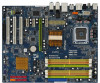
2.6 Expansion Slots (PCI and PCI Express Slots) There are 3 PCI slots and 4 PCI Express slots on this motherboard. PCI slots: PCI slots are used to install expansion cards that have the 32-bit PCI interface. PCIE slots: PCIE1 (PCIE x1 slot; White) is - ASRock P45TS | User Manual - Page 22
the CMOS right after you update the BIOS. If you need to clear the CMOS when you just finish updating the BIOS, you must boot up the system first, CPU, and try to overclock to FSB1333 orFSB1600 (by BIOS setting) you may face the problem, that DRAM frequency will be overclocked very high. Please use - ASRock P45TS | User Manual - Page 23
FSB2 4_5 FSB1 1_2 If you want to overclock the CPU you adopt to FSB1333 on this motherboard, you need to adjust the jumpers. Please short connectors. Placing jumper caps over the headers and connectors will cause permanent damage of the motherboard! FDD connector (33-pin FLOPPY1) (see p.11 No - ASRock P45TS | User Manual - Page 24
end to the motherboard connect the black end to the IDE devices 80-conductor ATA 66/100/133 cable Note: Please refer to the instruction of your ATA (SATA) Data Cable (Optional) eSATAII_TOP This eSATAII connector supports SATA data cable for external SATAII function. The current eSATAII - ASRock P45TS | User Manual - Page 25
on the I/O panel, there are two USB 2.0 headers on this motherboard. Each USB 2.0 header can support two USB 2.0 ports. WiFi/E Header (15-pin WIFI/E) (see GND1 D0-D0+ PexCLK PexCLK# USB+5V_1 PME# This header supports WiFi+AP function with ASRock WiFi-802.11g or WiFi-802.11n module, an easy-to- - ASRock P45TS | User Manual - Page 26
supports Jack Sensing, but the panel wire on the chassis must support HDA to function correctly. Please follow the instruction in our manual and chassis manual need to connect them for AC'97 audio panel. E. Enter BIOS Setup Utility. Enter Advanced Settings, and then select Chipset Configuration. - ASRock P45TS | User Manual - Page 27
fan (Quiet Fan) support, the 3-Pin CPU fan still can work successfully even without the fan speed control function. If you plan to connect the 3-Pin CPU fan to the CPU fan connector on this motherboard, please connect it to Pin 1-3. Pin 1-3 Connected 3-Pin Fan Installation ATX Power Connector (24 - ASRock P45TS | User Manual - Page 28
ATX 12V power supply to this connector. Though this motherboard provides 8-pin ATX 12V power connector, it can still work if you adopt a traditional 4-pin ATX 5 1 12V power supply. To use the 4-pin ATX motherboard. This IEEE 1394 header can support one IEEE 1394 port. This COM1 header supports - ASRock P45TS | User Manual - Page 29
motherboard with a HDMI_SPDIF header. This motherboard motherboard. For the proper installation of HDMI VGA card, please refer to the installation guide manual of HDMI VGA card vendor. Incorrect connection may cause permanent damage to this motherboard Otherwise, the motherboard and the user manual for - ASRock P45TS | User Manual - Page 30
Introduction What is eSATAII? This motherboard supports eSATAII interface, the external SATAII specification will replace USB 2.0 and IEEE 1394 to be a trend for external interface. NOTE: 1. If you set "Configure SATAII as" option in BIOS setup to AHCI or RAID mode, Hot Plug function is supported - ASRock P45TS | User Manual - Page 31
the SATA data cable to the eSATAII connector (eSATAII_TOP) 2. Use the eSATAII device cable to connect eSATAII device and the eSATAII port of the I/O shield. Connect one end of the eSATAII device cable to eSATAII device Connect the other end of the eSATAII device cable to eSATAII port of the - ASRock P45TS | User Manual - Page 32
Comparison between eSATAII and other devices IEEE 1394 USB 2.0 SATA eSATAII/SATAII 400Mb/s 480Mb/s 1.5Gb/s (1500Mb/s) 3.0Gb/s (3000Mb/s) 32 - ASRock P45TS | User Manual - Page 33
guide. Some default setting of SATAII hard disks may not be at SATAII mode, which operate with the best performance. In order to enable SATAII function, please follow the below instruction and pin 4 are shorted, SATA 1.5Gb/s will be enabled. On the other hand, if .com/hdd/support/download.htm The - ASRock P45TS | User Manual - Page 34
(RAID 0, RAID 1, RAID 10, RAID 5, and Intel Matrix Storage) functions. P45TS adopts Intel® ICH10 south bridge chipset that supports Serial ATA (SATA) / Serial ATAII (SATAII) hard disks. You may install SATA / SATAII hard disks on this motherboard for internal storage devices. This section will guide - ASRock P45TS | User Manual - Page 35
for SATA / SATAII HDDs and eSATAII Devices P45TS-R supports Hot Plug and Hot Swap functions for SATA / SATAII / eSATAII Devices in RAID / AHCI mode. P45TS supports Hot Plug and Hot Swap functions for SATA / SATAII / eSATAII Devices in AHCI mode. Intel® ICH10R / ICH10 south bridge chipset provides - ASRock P45TS | User Manual - Page 36
is installed into system properly. The latest SATA / SATAII driver is available on our support website: www.asrock.com 4. Make sure to use the SATA power cable & data cable, which are from our motherboard package. 5. Please follow below instructions step by step to reduce the risk of HDD crash or - ASRock P45TS | User Manual - Page 37
will cause the SATA / SATAII HDD damage and data loss. Step 1 Please connect SATA power cable 1x4-pin end Step 2 Connect SATA data cable to (White) to the power supply 1x4-pin cable. the motherboard follow below instruction sequence to process the Hot Unplug, improper procedure will cause the - ASRock P45TS | User Manual - Page 38
up BIOS. A. Enter BIOS SETUP UTILITY Advanced screen IDE Configuration. B. Set "SATAII Configuration" to [Enhanced], and then in the option "Configure SATAII as", please set the option to [RAID]. STEP 2: Make a SATA / SATAII Driver Diskette. A. Insert the Support CD into your optical drive to boot - ASRock P45TS | User Manual - Page 39
. Begin Windows® setup by booting from the installation CD. 4. At the beginning of Windows® setup, press F6 to install a third-party RAID driver. When prompted, insert the SATA / SATAII driver diskette containing the Intel® RAID driver. After reading the floppy disk, the driver will be presented. 39 - ASRock P45TS | User Manual - Page 40
necessary drivers. 6. Install the Intel(R) Matrix Storage Manager software via the CD-ROM included with your motherboard or after downloading it from the Internet. This will add the Intel(R) Matrix Storage Console which can be used to manage the RAID configuration. 7. After setting up a "RAID Ready - ASRock P45TS | User Manual - Page 41
the instruction to install Windows® VistaTM / VistaTM 64-bit OS on your system. When you see "Where do you want to install Windows?" page, please insert the ASRock Support CD into your optical drive, and click the "Load Driver" button on the left on the bottom to load the Intel® RAID drivers. Intel - ASRock P45TS | User Manual - Page 42
beginning of Windows® setup, press F6 to install a thirdparty AHCI driver. When prompted, insert the SATA / SATAII driver diskette containing the Intel® AHCI driver. After reading the floppy disk, the driver will be presented. Select the driver to install according to the mode you choose and the OS - ASRock P45TS | User Manual - Page 43
the optical drive to boot your system, and follow the instruction to install Windows® VistaTM / VistaTM 64-bit OS on your system. When you see "Where do you want to install Windows?" page, please insert the ASRock Support CD into your optical drive, and click the "Load Driver" button on the left - ASRock P45TS | User Manual - Page 44
Technology This motherboard supports Untied Overclocking Technology, which means during overclocking, FSB enjoys better margin due to fixed PCI / PCIE buses. Before you enable Untied Overclocking function, please enter "Overclock Mode" option of BIOS setup to set the selection from [Auto] to [Manual - ASRock P45TS | User Manual - Page 45
BIOS FWH chip on the motherboard stores the BIOS SETUP UTILITY. You may run the BIOS SETUP UTILITY when you start up the computer. Please press during the Power-On-Self-Test (POST) to enter the BIOS SETUP UTILITY, otherwise, POST will BIOS software is constantly being updated, the following BIOS - ASRock P45TS | User Manual - Page 46
Boot Security Exit System Overview System Time System Date [14:00:09] [Thu 07/10/2008] BIOS Version : P45TS-R P1.00 Processor Type : Intel (R) Core(TM)2 Duo CPU E7300 @ 2.66GHz (64bit) Processor Speed : 2666MHz Microcode Update : 10676/60B Cache Size : 3072KB Total Memory DDRII_A1 - ASRock P45TS | User Manual - Page 47
Monitor Boot Security Exit System Overview System Time System Date [14:00:09] [Thu 07/10/2008] BIOS Version : P45TS P1.00 Processor Type : Intel (R) Core(TM)2 Duo CPU E7300 @ 2.66GHz (64bit) Processor Speed : 2666MHz Microcode Update : 10676/60B Cache Size : 3072KB Total Memory DDRII_A1 - ASRock P45TS | User Manual - Page 48
, SuperIO Configuration, and USB Configuration. BIOS SETUP UTILITY Main Smart Advanced H/W Monitor Boot Security Exit Advanced Settings WARNING : Setting wrong values in below sections may cause system to malfunction. Overclock Configuration CPU Configuration Chipset Configuration ACPI - ASRock P45TS | User Manual - Page 49
item, which displays the ratio actual value of this motherboard. Ratio CMOS Setting If the ratio status is unlocked, you will find this item appear to allow you changing the ratio value of this motherboard. If the CPU you adopt supports EIST (Intel (R) SpeedStep(tm) tech.), and you plan to adjust - ASRock P45TS | User Manual - Page 50
select [533MHz (DDR3 1066)] or [667MHz (DDR3 1333)] for DDR3 memory modules. The configuration options depend on the CPU and memory module you adopt on this motherboard. Please refer to page 9 for the CPU FSB frequency and its corresponding memory support frequency. Standard Memory Info : 5-5-5-15 - ASRock P45TS | User Manual - Page 51
Manual 72V]. Configuration options for DDR3 memory modules: [Auto], [1. 47V], [1.53V], [1.59V], [1.65V], [1.71V], [1.77V], [1.83V], [1.88V], [1.95V], [2.05V], [2.11V], [2.17V], [2.23V], [2.29V], [2.34V] and [2.40V]. The default value of this feature is [Auto]. Mother Board - ASRock P45TS | User Manual - Page 52
BIOS SETUP UTILITY Advanced CPU Configuration Overclock Mode CPU Frequency (MHz) PCIE Frequency (MHz) Boot Failure Guard Spread Spectrum [Auto] [200] [100] [Enabled] [Auto] Ratio Status Ratio Actual Value Ratio CMOS Setting Unlocked (Min: 06, Max: 12) 12 [12] Enhanced Halt State Intel - ASRock P45TS | User Manual - Page 53
software to execute code. This option will be hidden if the current CPU does not support No-Excute Memory Protection. Hyper Threading Technology To enable this feature, it requires a computer system with an Intel Pentium® 4 processor that supports Hyper-Threading technology and an operating system - ASRock P45TS | User Manual - Page 54
)] for DDR3 memory modules. The configuration options depend on the CPU and memory module you adopt on this motherboard. Please refer to page 9 for the CPU FSB frequency and its corresponding memory support frequency. Flexibility Option The default value of this option is [Disabled]. It will allow - ASRock P45TS | User Manual - Page 55
5-5-5-15-36-5-3-3-3 DRAM tCL Use this item to adjust the means of memory accessing. Configuration options for DDR2 memory modules are [3], [4], [5], [6], [7] and [Auto]. Configuration options for DDR3 memory modules are are [5], [6], [7], [8], [9], [10] and [Auto]. DRAM tRCD This controls the number - ASRock P45TS | User Manual - Page 56
Express] as the boot graphic adapter priority. Auto], the onboard HD Audio will be disabled when PCI Sound Card P45TS only. Use this item to enable or disable CD-In of OnBoard HD Audio. If you plan to use this motherboard and [2.72V]. Configuration options for DDR3 memory modules: [Auto], [1.47V], [1. - ASRock P45TS | User Manual - Page 57
feature is [Enabled]. 3.4.4 ACPI Configuration BIOS SETUP UTILITY Advanced ACPI Configuration Suspend To RAM Repost Video on STR Resume Restore on RAM Use this item to select whether to auto-detect or disable the Suspend-toRAM feature. Select [Auto] will enable this feature if the OS supports - ASRock P45TS | User Manual - Page 58
[Power On] is selected, the AC/power resumes and the system starts to boot up when the power recovers. Ring-In Power On Use this item to enable if you plan to use this motherboard to submit Windows® VistaTM certification. 3.4.5 IDE Configuration BIOS SETUP UTILITY Advanced IDE Configuration - ASRock P45TS | User Manual - Page 59
* RAID option is only supported for P45TS-R. AHCI (Advanced Host Controller Interface) supports NCQ and other new features that will improve the device that you specify. We will use the "Primary IDE Master" as the example in the following instruction. BIOS SETUP UTILITY Advanced Primary IDE Master - ASRock P45TS | User Manual - Page 60
After selecting the hard disk information into BIOS, use a disk utility, such as FDISK, to -Sector Transfer) The default value of this item is [Auto]. If this feature is enabled, it will enhance hard disk performance by reading or writing more data during each transfer. PIO Mode Use this item - ASRock P45TS | User Manual - Page 61
item to enable or disable the PCI IDE BusMaster feature. 3.4.7 Floppy Configuration In this section, you may configure the type of your floppy drive. BIOS SETUP UTILITY Advanced Floppy Configuration Floppy A [1.44 MB 312"] Select the type of floppy drive connected to the system. +F1 F9 F10 ESC - ASRock P45TS | User Manual - Page 62
SETUP UTILITY Advanced Configure Super IO Chipset OnBoard Floppy Controller Serial Port Address Infrared Port Address [Enabled] [3F8 / IRQ4] [Disabled] Allow BIOS to Enable or Disable Floppy Controller. +F1 F9 F10 ESC Select Screen Select Item Change Option General Help Load Defaults Save and - ASRock P45TS | User Manual - Page 63
this item to enable or disable the USB 2.0 support. Legacy USB Support Use this option to select legacy support for USB devices. There are four configuration options: [Enabled], [Auto], [Disabled] and [BIOS Setup Only]. The default value is [BIOS Setup Only]. Please refer to below descriptions for - ASRock P45TS | User Manual - Page 64
motherboard temperature, CPU fan speed, chassis fan speed, and the critical voltage. BIOS SETUP UTILITY Main Smart Advanced H/W Monitor Boot function only when you install 4-pin CPU fan. Target CPU Temperature The target temperature will be between 45 C/113 F and 65 C/149 F. The default value is [50 - ASRock P45TS | User Manual - Page 65
section, it will display the available devices on your system for you to configure the boot settings and the boot priority. BIOS SETUP UTILITY Main Smart Advanced H/W Monitor Boot Security Exit Boot Settings Boot Settings Configuration Configure Settings during System Boot. 1st Boot Device 2nd - ASRock P45TS | User Manual - Page 66
and [ASRock]. The default value is [Auto]. Currently, the option [Auto] is set to Aircraft. Boot From Onboard LAN Use this item to enable or disable the Boot From Onboard LAN feature. Boot Up Num-Lock If this item is set to [On], it will automatically activate the Numeric Lock function after boot-up - ASRock P45TS | User Manual - Page 67
3.8 Exit Screen BIOS SETUP UTILITY Main Smart Advanced H/W Monitor Boot Security Exit Exit Options Save exit setup?" Select [OK] to exit the BIOS SETUP UTILITY without saving any changes. Discard Changes When you select this option, it will pop-out the following message, "Discard changes?" Select - ASRock P45TS | User Manual - Page 68
install the necessary drivers to activate the devices. 4.2.3 Utilities Menu The Utilities Menu shows the applications software that the motherboard supports. Click on a specific item then follow the installation wizard to install it. 4.2.4 Contact Information If you need to contact ASRock or want to
-
 1
1 -
 2
2 -
 3
3 -
 4
4 -
 5
5 -
 6
6 -
 7
7 -
8
-
9
-
10
-
11
-
12
-
13
-
14
-
15
-
16
-
17
-
18
-
19
-
20
-
21
-
22
-
23
-
24
-
25
-
26
-
27
-
28
-
29
-
30
-
31
-
32
-
33
-
34
-
35
-
36
-
37
-
38
-
39
-
40
-
41
-
42
-
43
-
44
-
45
-
46
-
47
-
48
-
49
-
50
-
51
-
52
-
53
-
54
-
55
-
56
-
57
-
58
-
59
-
60
-
61
-
62
-
63
-
64
-
65
-
66
-
67
-
68
 |
 |

1
P45TS-R /
P45TS
User Manual
Version 1.0
Published July 2008
Copyright©2008 ASRock INC. All rights reserved.