ASRock P4S55FX User Manual
ASRock P4S55FX Manual
 |
View all ASRock P4S55FX manuals
Add to My Manuals
Save this manual to your list of manuals |
ASRock P4S55FX manual content summary:
- ASRock P4S55FX | User Manual - Page 1
P4S55FX+ P4S55FX User Manual Version 1.01 Published March 2004 Copyright©2004 ASRock INC. All rights reserved. 1 - ASRock P4S55FX | User Manual - Page 2
any form or by any means, except duplication of documentation by the purchaser for backup purpose, without written consent of ASRock Inc. Products and corporate names appearing in this manual may or may not be registered trademarks or copyrights of their respective companies, and are used only for - ASRock P4S55FX | User Manual - Page 3
19 2.8 Making An SATA Driver Diskette 20 3 BIOS Setup 21 3.1 BIOS Setup Utility 21 3.1.1 BIOS Menu Bar 21 3.1.2 Legend Bar 21 3.2 Main Menu 22 3.3 Advanced, Security, Power, Boot, and Exit Menus ..... 24 4 Software Support 25 4.1 Install Operating System 25 4.2 Support CD Information 25 - ASRock P4S55FX | User Manual - Page 4
of this manual occur, the updated version will be available on ASRock website without further notice. You may find the latest memory and CPU support lists on ASRock website as well. ASRock website http://www.asrock.com 1.1 Package Contents ASRock P4S55FX+ or P4S55FX Motherboard (ATX Form - ASRock P4S55FX | User Manual - Page 5
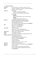
ATA 133 / Ultra DMA Mode 6 IDE2: ATA 133 / Ultra DMA Mode 6 Supports up to 4 IDE devices Serial ATA: 2 SATA connectors Supports up to 1.5Gb/s data transfer rate (SATA is only available on P4S55FX+ Motherboard) Floppy Port: Supports up to 2 floppy disk drives Audio: 5.1 channels AC'97 Audio - ASRock P4S55FX | User Manual - Page 6
advanced users' reference, see CAUTION 5) OS: Microsoft® Windows® 98SE / ME / 2000 / XP compliant CAUTION! 1. This motherboard supports Dual Channel Memory Technology. Before you implement Dual Channel Memory Technology, make sure to read the installation guide of memory modules on page 12 for - ASRock P4S55FX | User Manual - Page 7
1.3 Motherboard Layout (P4S55FX+) 1 23 45 6 7 21.8cm (8.6 in) PS2 Mouse PS2 Keyboard CD1 AUDIO1 1 AUX1 JR1 JL1 Audio CODEC Super I/O 24 23 2MB BIOS ATXPWR1 SiS 655FX LAN 1.5V_AGP1 PHY PCI 1 9 IDE1 10 11 PCI 2 P4S55FX+ SATA PCI 3 PCI 4 AGP 8X DDR400 PCI 5 GAME1 FSB800 USB2.0 5.1 - ASRock P4S55FX | User Manual - Page 8
1.4 Motherboard Layout (P4S55FX) 1 23 45 6 7 21.8cm (8.6 in) PS2 Mouse PS2 Keyboard 1 CD1 AUDIO1 1 AUX1 JR1 JL1 Audio CODEC Super I/O 22 21 2MB BIOS ATXPWR1 SiS 655FX LAN 1.5V_AGP1 PHY PCI 1 9 IDE1 10 11 PCI 2 P4S55FX PCI 3 PCI 4 AGP 8X DDR400 PCI 5 GAME1 ATA133 FSB800 USB2.0 - ASRock P4S55FX | User Manual - Page 9
1.5 ASRock I/O PlusTM (P4S55FX+ / P4S55FX) 1 2 3 4 5 11 10 9 1 Parallel Port 2 RJ-45 Port 3 Line In (Light Blue) 4 Line Out (Lime) 5 Microphone (Pink) 6 USB 2.0 Ports (USB4, USB5) 8 7 6 7 USB 2.0 Ports (USB0, USB1) 8 USB 2.0 - ASRock P4S55FX | User Manual - Page 10
Chapter 2 Installation P4S55FX+ / P4S55FX is an ATX form factor (12.0-in x 8.6-in, 30.5 cm x 21.8 cm) motherboard. Before you install the motherboard, study the configuration of your chassis to ensure that the motherboard fits into it. Pre-installation Precautions Take note of the following - ASRock P4S55FX | User Manual - Page 11
Step 2, 3 Step 4 2.2 Installation of CPU Fan and Heatsink This motherboard adopts 478-pin CPU socket to support Intel® Pentium® 4 / Celeron® CPU. It requires larger heatsink and 2). For proper installation, please kindly refer to the instruction manuals of the CPU fan and the heatsink. 11 - ASRock P4S55FX | User Manual - Page 12
2.3 Installation of Memory Modules (DIMM) P4S55FX+ / P4S55FX motherboard provides four 184-pin DDR (Double Data Rate) DIMM slots, and supports Dual Channel Memory Technology. For dual channel configuration, you always need to install identical (the same brand, speed, size and chip-type) DDR DIMM - ASRock P4S55FX | User Manual - Page 13
matches the break on the slot. notch break notch break The DIMM only fits in one correct orientation. It will cause permanent damage to the motherboard and the DIMM if you force the DIMM into the slot at incorrect orientation. Step 3. Firmly insert the DIMM into the slot until the retaining - ASRock P4S55FX | User Manual - Page 14
) There are 5 PCI slots and 1 AGP slot on P4S55FX+ / P4S55FX motherboard. PCI slots: PCI slots are used to install expansion cards that have the 32-bit PCI interface. AGP slot: The AGP slot is used to install a graphics card. The ASRock AGP slot has a special locking mechanism which can securely - ASRock P4S55FX | User Manual - Page 15
short the solder points for more than 3 seconds by using metal material, e.g., a paper clip. If you need to clear the CMOS when you just finish updating the BIOS, you must boot up the system first, and then shut it down before you do the clear-CMOS action. 15 - ASRock P4S55FX | User Manual - Page 16
IDE device on this motherboard, please set the IDE device as "Master". Please refer to the instruction of your IDE device vendor SATA) connectors are only available on P4S55FX+ motherboard. These two Serial ATA (SATA) connectors support SATA data cables for internal storage devices. The current SATA - ASRock P4S55FX | User Manual - Page 17
) Power Cable (Only for P4S55FX+ motherboard) (Optional) connect to the SATA HDD power connector connect to the power supply Please connect the black end of SATA power cable to the power connector on each drive. Then connect the white end of SATA power cable to the power connector of the power - ASRock P4S55FX | User Manual - Page 18
Chassis Fan Connector (3-pin CHA_FAN1) (see p.7 No. 16 / p.8, No. 15) CPU Fan Connector (3-pin CPU_FAN1) (see p.7 No. 2 / p.8, No. 2) Game Connector (15-pin GAME1) (see p.7 No. 22 / p.8, No. 20) ATX Power Connector (20-pin ATXPWR1) (see p.7 No. 29 / p.8, No. 27) GND +12V CHA_FAN_SPEED Please - ASRock P4S55FX | User Manual - Page 19
HDDs P4S55FX+ motherboard supports Hot Plug function for SATA Devices. Usually, each power wire will provide 2 power connectors for HDDs. We suggest you to connect SATA HDDs to different power wires to prevent intervention. As to Hot Swap support, please refer to the updates of later version driver - ASRock P4S55FX | User Manual - Page 20
Diskette If you want to install Windows 2000 or Windows XP on your SATA HDDs, you will need to make an SATA driver diskette before you start the OS installation. STEP 1: Insert the ASRock Support CD into your optical drive to boot your system. (Do NOT insert any floppy diskette into the floppy - ASRock P4S55FX | User Manual - Page 21
use the BIOS Setup Utility to configure your system. The Flash Memory on the motherboard stores the BIOS Setup Utility. You may run the BIOS Setup Utility among the predetermined choices. Because the BIOS software is constantly being updated, the following BIOS setup screens and descriptions are for - ASRock P4S55FX | User Manual - Page 22
Processor Type Processor Speed Cache Size Microcode Update Total Memory DDR1 DDR2 DDR3 DDR4 AMIBIOS SETUP UTILITY - VERSION 3.31a Security Power Boot Exit Jan 2 2004 Fri 10:07:40 [ Setup Help ] Month: Jan - Dec Day: 01 - 31 Year: 1980 - 2099 P4S55FX+ BIOS P1.00 Pentium (R) 4 CPU 2400 MHz 512 - ASRock P4S55FX | User Manual - Page 23
may due to that the hard disk is too old or too new. If the hard disk was already formatted on an older system, the BIOS Setup may detect incorrect parameters. In these cases, select [User] to manually enter the IDE hard disk drive parameters. After entering the hard disk information into - ASRock P4S55FX | User Manual - Page 24
Maximum Capacity This field shows the drive's maximum capacity as calculated by the BIOS based on the drive information you entered. LBA Mode This allows user to select the LBA mode for a hard disk > 512 MB under DOS and Windows; for Netware and UNIX user, select [Off] to disable the LBA mode. - ASRock P4S55FX | User Manual - Page 25
detects installed devices. Install the necessary drivers to activate the devices. 4.2.3 Utilities Menu The Utilities Menu shows the applications software that the motherboard supports. Click on a specific item then follow the installation wizard to install it. 4.2.4 ASRock PC-DIY Live Demo Program - ASRock P4S55FX | User Manual - Page 26
Exit." 1. Advanced BIOS Setup Menu Main installed motherboard. DRAM Frequency: If [Auto] is selected, the motherboard supports Hyper-Threading technology and an operating system that includes optimization for this technology, such as Microsoft® Windows® XP. Set to [Auto] if using Microsoft® Windows - ASRock P4S55FX | User Manual - Page 27
], [2X], and [1X]. The default value is [Auto]. AGP Fast Write: This allows you to enable or disable the feature of AGP fast write protocol support. AGP Aperture Size: It refers to a section of the PCI memory address range used for graphics memory. It is recommended to leave this field at - ASRock P4S55FX | User Manual - Page 28
/AGP/PCI Frequency mode: If the item CPU Host Frequency is set to [Manual], it allows you to set the value for this item. You may set : [Auto], [2T], [2.5T], [3T]. Please note that not all the DDR DIMMs can support CAS latency=3T. DRAM Precharge Time: Use this to select among [Auto], [3T], [2T], - ASRock P4S55FX | User Manual - Page 29
Parallel Port Mode EPP Version Parallel Port IRQ Parallel Port DMA Channel OnBoard Midi Port Midi IRQ Select OnBoard Game Port OnBoard IDE OnBoard SATA OnBoard LAN OnBoard AC' 97 Audio Auto Auto Disabled Auto ECP + EPP 1.9 Auto Auto Disabled 5 200H Both Enabled Enabled Auto to enable or - ASRock P4S55FX | User Manual - Page 30
]. OnBoard IDE: This allows you to enable or disable the onboard IDE controller. OnBoard SATA: This allows you to enable or disable the onboard SATA controller. This option is available only for P4S55FX+ motherboard. OnBoard LAN: This allows you to enable or disable the onboard LAN feature. OnBoard - ASRock P4S55FX | User Manual - Page 31
p assword. Password Check: Select the check point for "Password Check". Configuration options: [Setup], [Always]. If [Setup] option is selected, the "Password Check" is performed before BIOS setup. If [Always] option is selected, the "Password Check" is performed before both boot-up and - ASRock P4S55FX | User Manual - Page 32
(S3) feature. Select [Auto] will enable this feature if the system supports it. Repost Video on S3 Resume: This feature allows you to repost video on S3 resume. It is recommended to enable this feature under Microsoft® Windows® 98 / ME. Restore on AC/Power Loss: This allows you to set - ASRock P4S55FX | User Manual - Page 33
4. Boot Setup Menu Main Advanced AMIBIOS SETUP UTILITY - VERSION 3.31a Security Power Boot Exit Quick Boot Mode Boot Up Num-Lock Boot To OS/2 Boot From Network Enabled On No Disabled [ Setup Help ] to enable or disable the quick boot mode. Boot Device Priority F1:Help Esc:Exit : - ASRock P4S55FX | User Manual - Page 34
the sub-menu, the message "Save current settings and exit" will appear. If you press , it will save the current settings and exit the BIOS SETUP Utility. Exit Discarding Changes: After you enter the submenu, the message "Quit without saving changes" will appear. If you press , you will
-
 1
1 -
 2
2 -
 3
3 -
 4
4 -
 5
5 -
 6
6 -
 7
7 -
8
-
9
-
10
-
11
-
12
-
13
-
14
-
15
-
16
-
17
-
18
-
19
-
20
-
21
-
22
-
23
-
24
-
25
-
26
-
27
-
28
-
29
-
30
-
31
-
32
-
33
-
34
 |
 |

1
P4S55FX+
P4S55FX
User Manual
Version 1.01
Published March 2004
Copyright©2004 ASRock INC. All rights reserved.