ASRock P4S61 User Manual
ASRock P4S61 Manual
 |
View all ASRock P4S61 manuals
Add to My Manuals
Save this manual to your list of manuals |
ASRock P4S61 manual content summary:
- ASRock P4S61 | User Manual - Page 1
P4S61 User Manual Version 1.0 Published October 2003 Copyright©2003 ASRock INC. All rights reserved. 1 - ASRock P4S61 | User Manual - Page 2
intent to infringe. Disclaimer: Specifications and information contained in this manual are furnished for informational use only and subject to change without notice, and should not be constructed as a commitment by ASRock. ASRock assumes no responsibility for any errors or omissions that may appear - ASRock P4S61 | User Manual - Page 3
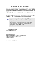
1 Introduction 4 1.1 Package Contents 4 1.2 Specifications 5 1.3 Motherboard Layout 7 1.4 ASRock I/OTM 8 2 Installation 9 2.1 Screw Holes 9 2.2 Pre-installation Precautions 9 2.3 CPU Installation 10 2.4 Installation of Heatsink and CPU fan 10 2.5 Installation of Memory Modules (DIMM 11 - ASRock P4S61 | User Manual - Page 4
any modifications of this manual occur, the updated version will be available on ASRock website without further notice. You may find the latest memory and CPU support lists on ASRock website as well. ASRock website http://www.asrock.com 1.1 Package Contents ASRock P4S61 Motherboard (Micro ATX Form - ASRock P4S61 | User Manual - Page 5
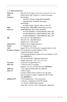
1.2 Specifications Platform: CPU: Micro ATX Form Factor: 9.6-in x 8.4-in, 24.4 cm x 21.3 cm Socket 478 for Intel® Pentium® 4 / Celeron® processor Chipsets: North Bridge: SiS 661FX chipset, FSB @ 800/533/400MHz, supports Hyper-Threading Technology South Bridge: SiS 963L chipset, supports USB - ASRock P4S61 | User Manual - Page 6
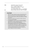
, remember to spray thermal grease between the CPU and the heatsink when you install the PC system. 2. Do NOT use a 3.3V AGP card on the AGP slot of P4S61 motherboard! It may cause permanent damage! 3. Power Management for USB 2.0 works fine under Microsoft® Windows® XP SP1/2000 SP4. It may not work - ASRock P4S61 | User Manual - Page 7
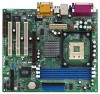
ATXPWR1 LAN (optional) USB 2.0 Ports USB 2.0 Ports Line out LiLInnineein LAN PHY AUX1 CD1 MMIniicc in 1 AUDIO1 JR1 JL1 AUDIO CODEC SiS 661 FX Chipset AGP 8X AGP1 PCI 1 IDE2 IDE1 SiS 963L CMOS Battery CLRCMOS1 Super I/O 2MB BIOS PCI 2 AMR1 FSB800 PCI 3 P4S61 21 USB45 1 COM1 - ASRock P4S61 | User Manual - Page 8
1.4 ASRock I/OTM 1 Parallel Port 2 RJ-45 Port 3 Game Port 4 Microphone (Pink) 5 Line In (Light Blue) 6 Line Out (Lime) 7 USB 2.0 Ports 8 VGA Port 9 PS/2 Keyboard Port (Purple) 10 PS/2 Mouse Port (Green) 8 - ASRock P4S61 | User Manual - Page 9
Precautions Take note of the following precautions before you install motherboard components or change any motherboard settings. 1. Unplug the power cord from the wall socket before touching any component. 2. To avoid damaging the motherboard components due to static electricity, NEVER place your - ASRock P4S61 | User Manual - Page 10
. Make sure that the CPU and the heatsink are securely fastened and in good contact with each other. Then connect the CPU fan to the CPU_FAN connector (CPU_FAN1, see page 7, No. 5). For proper installation, please kindly refer to the instruction manuals of the CPU fan and heatsink vendors. 10 - ASRock P4S61 | User Manual - Page 11
2.5 Installation of Memory Modules (DIMM) P4S61 motherboard provides three 184-pin DDR (Double Data Rate) break The DIMM only fits in one correct orientation. It will cause permanent damage to the motherboard and the DIMM if you force the DIMM into the slot at incorrect orientation. Step 3. Firmly - ASRock P4S61 | User Manual - Page 12
slot: The AMR slot is used to insert an ASRock MR card (optional) with v.92 Modem functionality. AGP slot: The AGP slot is AGP 3.5 compliant and it supports an 8X / 4X AGP card. Do NOT use a 3.3V AGP card on the AGP slot of P4S61 motherboard! It may cause permanent damage! Installing an expansion - ASRock P4S61 | User Manual - Page 13
panel audio connectors can work. Clear CMOS Solder Points (CLRCMOS1) (see p.7 item 11) solder points Note: CLRCMOS1 allows you to clear the data in CMOS. The data in CMOS includes system setup information such as system password, date, time, and system setup parameters. To clear and reset the - ASRock P4S61 | User Manual - Page 14
IDE device on this motherboard, please set the IDE device as "Master". Please refer to the instruction of your IDE device ASRock I/OTM provides you 4 default USB 2.0 ports on the rear panel. If the rear USB 2.0 ports are not sufficient, this USB 2.0 connector is available to support 2 additional USB - ASRock P4S61 | User Manual - Page 15
14) CPU fan sound sources such as a CD-ROM, DVD/ROM, TV tuner card, or MPEG card. GND +5VA BACKOUT-R BACKOUT-L 1 A U D - O U T- L GND A U D - O U T- R MIC-POWER MIC PLED+ PLEDPWRBTN# GND 1 DUMMY RESET# GND HDLEDHDLED+ This is an interface for front panel audio supports a serial port module. 15 - ASRock P4S61 | User Manual - Page 16
BIOS Setup Utility. The Flash Memory on the motherboard stores the BIOS Setup Utility. When you start up the computer, there is a chance for you to run the BIOS the predetermined choices. Because the BIOS software is constantly being updated, the following BIOS setup screens and descriptions are for - ASRock P4S61 | User Manual - Page 17
BIOS Version Processor Type Processor Speed Cache Size Microcode Update Total Memory DDR1 DDR2 DDR3 AMIBIOS SETUP UTILITY - VERSION 3.31a Security Power Boot Exit Oct17 2003 Fri 20:07:40 [ Setup Help ] Month: Jan - Dec Day: 01 - 31 Year: 1980 - 2099 P4S61 BIOS P1.00 Pentium (R) 4 CPU 2400 - ASRock P4S61 | User Manual - Page 18
may due to that the hard disk is too old or too new. If the hard disk was already formatted on an older system, the BIOS Setup may detect incorrect parameters. In these cases, select [User] to manually enter the IDE hard disk drive parameters. After entering the hard disk information into - ASRock P4S61 | User Manual - Page 19
shows the drive's maximum capacity as calculated by the BIOS based on the drive information you entered. LBA Mode for a hard disk > 512 MB under DOS and Windows; for Netware and UNIX user, select [Off] to disable 3.3 Advanced, Security, Power, Boot, and Exit Menus Detailed descriptions of these menus - ASRock P4S61 | User Manual - Page 20
installed devices. Please install the necessary drivers to activate the devices. 4.2.3 Utilities Menu The Utilities Menu shows the applications software that the motherboard supports. Click on a specific item then follow the installation wizard to install it. 4.2.4 ASRock PC-DIY Live Demo Program - ASRock P4S61 | User Manual - Page 21
requires a computer system with an Intel® Pentium®4 processor that supports Hyper-Threading technology and an operating system that includes optimization for this technology, such as Microsoft® Windows® XP. Set to [Auto] if using Microsoft® Windows® XP, or Linux kernel version 2.4.18 or higher. This - ASRock P4S61 | User Manual - Page 22
SETUP UTILITY - VERSION 3.31a Chipset Configuration [ Setup Help ] AGP Aperture Size Onboard VGA Share Memory USB Controller USB Device Legacy Support USB 2.0 Controller DRAM CAS# Latency MA 1T/2T Select CPU Thermal Throttling AGP / PCI Fix Frequency 64MB Auto Enabled Disabled Enabled Auto MA2T - ASRock P4S61 | User Manual - Page 23
you to keep the default value unless your PCI expansion cards' specifications require other settings. Primary Graphics Adapter: This allows you to select Midi IRQ Select OnBoard Game Port OnBoard IDE OnBoard LAN OnBoard AC' 97 Audio OnBoard MC' 97 Modem Auto Auto Disabled Auto ECP+EPP 1.9 Auto Auto - ASRock P4S61 | User Manual - Page 24
onboard AC'97 Audio feature. OnBoard MC'97 Modem: Select [Auto] or [Disabled] for the onboard MC'97 Modem feature. System Hardware Monitor: You can check the status of the hardware on your system. It allows you to monitor the parameters for CPU temperature, Motherboard temperature, CPU fan speed - ASRock P4S61 | User Manual - Page 25
UTILITY - VERSION 3.31a Security Power Boot Exit Supervisor Password User Password Set Supervisor Password Set User Password Clear Clear [ Enter ] [ Enter ] [ is selected, the "Password Check" is performed before BIOS setup. If [Always] option is selected, the "Password Check" is performed before - ASRock P4S61 | User Manual - Page 26
[Auto] will enable this feature if the system supports it. Repost Video on S3 Resume: This feature It is recommended to enable this feature under Microsoft® Windows® 98 / ME. Restore on AC/Power Loss: the AC/Power resumes and the system starts to boot up when the power recovers. Ring-In Power On - ASRock P4S61 | User Manual - Page 27
Item :Select Menu +/-:Change Values Enter:Select Sub-Menu F9:Setup Defaults F10:Save & Exit Quick Boot Mode: Enable this mode will speed up the boot-up routine by skipping memory retestings. Boot Up Num-Lock: If this is enabled, it will automatically activate the Numeric Lock function after - ASRock P4S61 | User Manual - Page 28
Boot Exit Exit Saving Changes Exit Discarding Changes Load Default Settings Discard Changes [ Enter ] [ Enter ] [ Enter ] [ Enter ] [ Setup Help ] Exits and saves the changes to CMOS >, it will save the current settings and exit the BIOS SETUP Utility. Exit Discarding Changes: After you enter the
-
 1
1 -
 2
2 -
 3
3 -
 4
4 -
 5
5 -
 6
6 -
 7
7 -
8
-
9
-
10
-
11
-
12
-
13
-
14
-
15
-
16
-
17
-
18
-
19
-
20
-
21
-
22
-
23
-
24
-
25
-
26
-
27
-
28
 |
 |

1
P4S61
User Manual
Version 1.0
Published October 2003
Copyright©2003 ASRock INC. All rights reserved.