ASRock P4VM8 User Manual
ASRock P4VM8 Manual
 |
View all ASRock P4VM8 manuals
Add to My Manuals
Save this manual to your list of manuals |
ASRock P4VM8 manual content summary:
- ASRock P4VM8 | User Manual - Page 1
P4VM8 User Manual Version 1.0 Published April 2005 Copyright©2005 ASRock INC. All rights reserved. 1 - ASRock P4VM8 | User Manual - Page 2
owners' benefit, without intent to infringe. Disclaimer: Specifications and information contained in this manual are furnished for informational use only and subject to change without notice, and should not be constructed as a commitment by ASRock. ASRock assumes no responsibility for any errors or - ASRock P4VM8 | User Manual - Page 3
1. Introduction 5 1.1 Package Contents 5 1.2 Specifications 6 1.3 Motherboard Layout 8 1.4 ASRock I/O Plus 9 TM 2. Installation 10 Pre-installation Precautions 10 2.1 CPU Installation 11 2.2 Installation of CPU Fan and Heatsink 11 2.3 Installation of Memory Modules (DIMM 12 2.4 Expansion - ASRock P4VM8 | User Manual - Page 4
4. Software Support 35 4.1 Install Operating System 35 4.2 Support CD Information 35 4.2.1 Running Support CD 35 4.2.2 Drivers Menu 35 4.2.3 Utilities Menu 35 4.2.4 Contact Information 35 4 - ASRock P4VM8 | User Manual - Page 5
guide to BIOS setup and information of the Support CD. Because the motherboard specifications and the BIOS software might be updated, the content of this manual will be subject to change without notice. In case any modifications of this manual occur, the updated version will be available on ASRock - ASRock P4VM8 | User Manual - Page 6
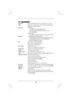
CPU: Socket 478, supports Intel® Pentium® 4 (Prescott, Northwood, Willimate) / Celeron® processor Chipsets: North Bridge: VIA PM800, FSB @ 800/533/400 MHz, with Intel® Hyper-Threading Technology ready (see CAUTION 1) South Bridge: VIA VT8237R, supports USB 2.0, ATA 133, SATA 1.5Gb/s Memory - ASRock P4VM8 | User Manual - Page 7
Audio Jack: Line In / Line Out / Microphone BIOS: AMI BIOS Supports "Plug and Play" ACPI 1.1 compliance wake up events Supports jumperfree SMBIOS 2.3.1 support CPU frequency stepless control (only for advanced users' reference, see CAUTION 5) OS: Microsoft® Windows® 98SE / ME / 2000 / XP - ASRock P4VM8 | User Manual - Page 8
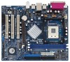
Battery JR1 JL1 CLRCMOS1 5.1CH CD1 AUX1 Audio CODEC AMR1 VPIMACh80ip0set AGP 8X ATA133 1.5V_AGP1 IDE1 IDE2 PCI 1 ` P4VM8 PCI 2 USB2.0 PCI 3 1 COM1 VIA VT8237R SATA 1 USB67 PANEL 1 PLED PWRBTN 1 1 SPEAKER1 HDLED RESET SATA2 SATA1 DDR400 Prescott 800 DDR1 (64/72 bit, 184-pin module - ASRock P4VM8 | User Manual - Page 9
1.4 ASRock I/O PlusTM 1 11 10 9 1 Parallel Port 2 RJ-45 Port 3 Line In (Light Blue) 4 Line Out (Lime) 5 Microphone (Pink) 6 Shared USB 2.0 Ports (USB45) 2 3 4 5 8 7 6 7 USB 2.0 Ports (USB01) 8 USB 2.0 Ports (USB23) 9 VGA Port 10 PS/2 Keyboard Port (Purple) 11 PS/2 Mouse Port (Green) 9 - ASRock P4VM8 | User Manual - Page 10
Precautions Take note of the following precautions before you install motherboard components or change any motherboard settings. 1. Unplug the power cord from the wall socket before touching any component. 2. To avoid damaging the motherboard components due to static electricity, NEVER place your - ASRock P4VM8 | User Manual - Page 11
to 90° STEP 2/STEP 3: Match The CPU Marked Corner to The Socket Marked Corner STEP 4: Push Down And Lock The Socket Lever 2.2 Installation of CPU Fan and Heatsink This motherboard adopts 478-pin CPU socket to support Intel® Pentium® 4 / Celeron® CPU. It requires larger heatsink and cooling fan - ASRock P4VM8 | User Manual - Page 12
2.3 Installation of Memory Modules (DIMM) P4VM8 motherboard provides two 184-pin DDR (Double Data Rate) break The DIMM only fits in one correct orientation. It will cause permanent damage to the motherboard and the DIMM if you force the DIMM into the slot at incorrect orientation. Step 3. Firmly - ASRock P4VM8 | User Manual - Page 13
P4VM8 motherboard. PCI slots: PCI slots are used to install expansion cards that have the 32-bit PCI interface. AMR slot: The AMR slot is used to insert an ASRock necessary hardware settings for the card before you start the installation. Step 2. Remove the system unit cover (if your motherboard is - ASRock P4VM8 | User Manual - Page 14
Open Jumper Setting PS2_USB_PWR1 1_2 2_3 Short pin2, pin3 to enable (see p.8, No. 1) +5V +5VSB +5VSB ( JR1 are short, both the front panel and the rear panel audio connectors can work. Clear CMOS (CLRCMOS1, 2-pin jumper) you just finish updating the BIOS, you must boot up the system - ASRock P4VM8 | User Manual - Page 15
ATA (SATA) connectors support SATA data cables for internal storage devices. The current SATA interface allows up to 1.5 Gb/s data transfer rate. Serial ATA (SATA) Data Cable Either end of the SATA data cable can be connected to the SATA hard disk or the SATA connector on the motherboard. 15 - ASRock P4VM8 | User Manual - Page 16
ASRock I/O PlusTM will not be able to function. This header supports an optional wireless transmitting and receiving infrared module. Internal Audio you to receive stereo audio input from sound sources such as a CD-ROM, DVD-ROM, TV tuner card, or MPEG card. Front Panel Audio Header (9-pin AUDIO1) - ASRock P4VM8 | User Manual - Page 17
(see p.8, No. 27) CHA_FAN_SPEED +12V GND CPU Fan Connector (3-pin CPU_FAN1) (see p.8, No. black wire to the ground pin. Please connect the CPU fan cable to this connector and match the black to power up. Please install the heatsink and the CPU fan before installing ATX 12V connector; otherwise, it - ASRock P4VM8 | User Manual - Page 18
4: Connect the other end of the SATA data cable to the SATA hard disk. 2.8 Hot Plug and Hot Swap Functions for SATA HDDs P4VM8 motherboard supports Hot Plug and Hot Swap functions for SATA Devices. NOTE What is Hot Plug Function? If the SATA HDDs are NOT set for RAID configuration, it is called "Hot - ASRock P4VM8 | User Manual - Page 19
the document in the Support CD, "Guide to SATA Hard Disks Installation and RAID Configuration", which is located in the folder at the following path: .. \ SATA RAID BIOS STEP 3: Install Windows 2000 / Windows XP OS on your system. After making a SATA driver diskette and using "SATA RAID BIOS" to set - ASRock P4VM8 | User Manual - Page 20
Operation Mode" option from [RAID] to [non-RAID]. STEP 2: Install Windows 98 / ME / 2000 / XP OS on your system. After setting up BIOS, you can start to install Windows 98 / ME / 2000 / XP on your system. If you don't want to set up RAID functions, there is no need to make a SATA driver diskette. 20 - ASRock P4VM8 | User Manual - Page 21
BIOS SETUP UTILITY to configure your system. The Flash Memory on the motherboard stores the BIOS SETUP UTILITY. You may run the BIOS Because the BIOS software is constantly being updated, the following BIOS setup the advanced BIOS features H/W Monitor To display current hardware status Boot - ASRock P4VM8 | User Manual - Page 22
Advanced H/W Monitor Boot Security Exit System Overview System Time System Date [17:00:09] [Thu 04/28/2005] BIOS Version : P4VM8 BIOS P1.00 Processor Type : Intel (R) Pentium (R) 4 CPU 2.40 GHz Processor Speed : 2400 MHz Cache Size : 512KB Microcode Update : 0F24/1E Total Memory DIMM - ASRock P4VM8 | User Manual - Page 23
Defaults Save and Exit Exit v02.54 (C) Copyright 1985-2003, American Megatrends, Inc. CPU Host Frequency While entering setup, BIOS auto detects the present CPU host frequency of this motherboard. The actual CPU host frequency will show in the following item. Spread Spectrum Select [Auto] for the - ASRock P4VM8 | User Manual - Page 24
Microsoft® Windows® XP, or Linux kernel version 2.4.18 or higher. This option will be hidden if the installed CPU does not support Hyper-Threading technology. Max CPUID Value Limit For Prescott CPU only, some OSes (ex. NT4.0) cannot handle the function with disable. This should be enabled in order - ASRock P4VM8 | User Manual - Page 25
is set to [Auto]. When the total memory is equal or above 256MB, the share memory size will be [64MB]; otherwise, please set the share memory size to [32MB]. PCI Delay Transaction Enable PCI Delay Transaction feature will free the PCI Bus when the CPU is accessing 8-bit ISA cards. Disable this - ASRock P4VM8 | User Manual - Page 26
'97 Modem feature. 3.3.3 ACPI Configuration BIOS SETUP UTILITY Advanced ACPI Configuration Suspend To ] [Disabled] [Disabled] [Disabled] [Disabled] Select auto-detect or disable the STR feature. +F1 F9 F10 ESC Select Ring-In Power On Use this item to enable or disable Ring-In signals to turn on - ASRock P4VM8 | User Manual - Page 27
IDE Configuration OnBoard IDE Controller SATA Operation Mode Primary IDE Master Primary IDE Slave Secondary IDE Master Secondary IDE Slave [Both] [RAID] [Hard Disk] [Not Detected] [Not Detected] [Not Detected] DISABLED: disables the integrated IDE Controller. PRIMARY: enables only the Primary IDE - ASRock P4VM8 | User Manual - Page 28
detect the hard disk drive. After selecting the hard disk information into BIOS DOS and Windows; for enable or disable the S.M.A.R.T. (Self-Monitoring, Analysis, and Reporting Technology) feature. Configuration options: [Disabled], [Auto], [Enabled]. 32-Bit Data Transfer Use this item to enable - ASRock P4VM8 | User Manual - Page 29
the installed PCI expansion cards' specifications require other settings. PCI IDE BusMaster Use this item to enable or disable the PCI IDE BusMaster feature. 3.3.6 Floppy Configuration In this section, you may configure the type of your floppy drive. BIOS - ASRock P4VM8 | User Manual - Page 30
Port Address Parallel Port Address Parallel Port Mode EPP Version ECP Mode DMA Channel Parallel Port IRQ [Enabled] [3F8 / IRQ4] [Disabled] [378] [ECP + EPP] [1.9] [DMA3] [IRQ7] Allow BIOS to Enable or Disable Floppy Controller. +F1 F9 F10 ESC Select Screen Select Item Change Option General Help - ASRock P4VM8 | User Manual - Page 31
3.3.8 USB Configuration BIOS SETUP UTILITY Advanced USB Configuration USB Devices Enabled : None USB Controller USB 2.0 Support Legacy USB Support [Enabled] [Enabled] [Disabled] To enable or disable the onboard USB controllers. +F1 F9 F10 ESC Select Screen Select Item Change Option General - ASRock P4VM8 | User Manual - Page 32
of the CPU temperature, motherboard temperature, CPU fan speed, chassis fan speed, and the critical voltage. BIOS SETUP UTILITY Main Advanced H/W Monitor Boot Security Exit Hardware Health Event Monitoring CPU Temperature M / B Temperature CPU Fan Speed Chassis Fan Speed Vcore + 3.30V - ASRock P4VM8 | User Manual - Page 33
Use this item to enable or disable the Boot From Network feature. VIA SATA Raid Utility Use this to enable or disable VIA VT8237 SATA Raid BIOS Utility during POST. Boot , you may also clear it. BIOS SETUP UTILITY Main Advanced H/W Monitor Boot Security Exit Security Settings Supervisor - ASRock P4VM8 | User Manual - Page 34
and exit setup?" Select [OK] to save the changes and exit the BIOS SETUP UTILITY. Discard Changes and Exit When you select this option, it message, "Discard changes and exit setup?" Select [OK] to exit the BIOS SETUP UTILITY without saving any changes. Discard Changes When you select this option - ASRock P4VM8 | User Manual - Page 35
install the necessary drivers to activate the devices. 4.2.3 Utilities Menu The Utilities Menu shows the applications software that the motherboard supports. Click on a specific item then follow the installation wizard to install it. 4.2.4 Contact Information If you need to contact ASRock or want to
-
 1
1 -
 2
2 -
 3
3 -
 4
4 -
 5
5 -
 6
6 -
 7
7 -
8
-
9
-
10
-
11
-
12
-
13
-
14
-
15
-
16
-
17
-
18
-
19
-
20
-
21
-
22
-
23
-
24
-
25
-
26
-
27
-
28
-
29
-
30
-
31
-
32
-
33
-
34
-
35
 |
 |
1
P4VM8
User Manual
Version 1.0
Published April 2005
Copyright©2005 ASRock INC. All rights reserved.