ASRock P4VM800 User Manual - Page 11
CPU Installation, Installation of CPU Fan and Heatsink - socket 478 intel motherboard
 |
View all ASRock P4VM800 manuals
Add to My Manuals
Save this manual to your list of manuals |
Page 11 highlights
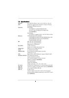
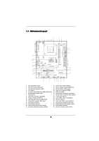
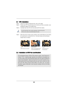
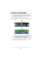
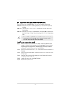
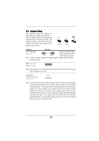
2.1 CPU Installation Step 1. Unlock the socket by lifting the lever up to a 90° angle. Step 2. Position the CPU directly above the socket such that its marked corner matches the base of the socket lever. Step 3. Carefully insert the CPU into the socket until it fits in place. The CPU fits only in one correct orientation. DO NOT force the CPU into the socket to avoid bending of the pins. Step 4. When the CPU is in place, press it firmly on the socket while you push down the socket lever to secure the CPU. The lever clicks on the side tab to indicate that it is locked. Lift Lever Up to 90° CPU Marked Corner Socket Marked Corner STEP 1: Lift The Socket Lever Up to 90° STEP 2/STEP 3: Match The CPU Marked Corner to The Socket Marked Corner STEP 4: Push Down And Lock The Socket Lever 2.2 Installation of CPU Fan and Heatsink This motherboard adopts 478-pin CPU socket to support Intel® Pentium® 4 / Celeron® CPU. It requires larger heatsink and cooling fan to dissipate heat. You also need to spray thermal grease between the CPU and the heatsink to improve heat dissipation. Make sure that the CPU and the heatsink are securely fastened and in good contact with each other. Then connect the CPU fan to the CPU_FAN connector (CPU_FAN1, see p.8 No. 30). For proper installation, please kindly refer to the instruction manuals of the CPU fan and the heatsink. 11
-
 1
1 -
2
-
3
-
4
-
5
-
 6
6 -
 7
7 -
 8
8 -
 9
9 -
 10
10 -
 11
11 -
 12
12 -
 13
13 -
 14
14 -
 15
15 -
 16
16 -
17
-
18
-
19
-
20
-
21
-
22
-
23
-
24
-
25
-
26
-
27
-
28
-
29
-
30
-
31
-
32
-
33
-
34
-
35
 |
 |