ASRock P4VM800 User Manual - Page 17
ATX 12V Connector - cpu support
 |
View all ASRock P4VM800 manuals
Add to My Manuals
Save this manual to your list of manuals |
Page 17 highlights
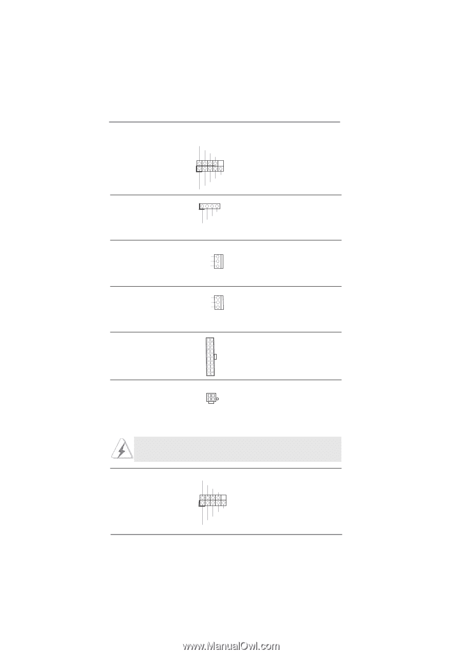
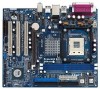
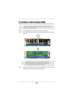
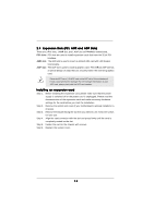
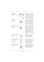
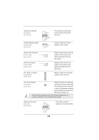
System Panel Header (9-pin PANEL1) (see p.8, No. 16) Chassis Speaker Header (4-pin SPEAKER 1) (see p.8, No. 17) PLED+ PLEDPWRBTN# GND 1 DUMMY RESET# GND HDLEDHDLED+ 1 SPEAKER DUMMY DUMMY +5V This header accommodates several system front panel functions. Please connect the chassis speaker to this header. Chassis Fan Connector (3-pin CHA_FAN1) (see p.8, No. 27) CHA_FAN_SPEED +12V GND CPU Fan Connector (3-pin CPU_FAN1) (see p.8, No. 30) CPU_FAN_SPEED +12V GND ATX Power Connector (20-pin ATXPWR1) (see p.8, No. 8) Please connect the chassis fan cable to this connector and match the black wire to the ground pin. Please connect the CPU fan cable to this connector and match the black wire to the ground pin. Please connect an ATX power supply to this connector. ATX 12V Connector (4-pin ATX12V1) (see p.8, No. 2) Please note that it is necessary to connect a power supply with ATX 12V plug to this connector so that it can provides sufficient power. Failing to do so will cause the failure to power up. Please install the heatsink and the CPU fan before installing ATX 12V connector; otherwise, it may cause permanent damage! Serial port connector (9-pin COM1) (see p.8 item 19) RRXD1 DDTR#1 DDSR#1 CCTS#1 1 RRI#1 RRTS#1 GND TTXD1 DDCD#1 17 This COM1 connector supports a serial port module.
-
 1
1 -
2
-
3
-
4
-
5
-
6
-
7
-
8
-
9
-
10
-
11
-
 12
12 -
 13
13 -
 14
14 -
 15
15 -
 16
16 -
 17
17 -
 18
18 -
 19
19 -
 20
20 -
 21
21 -
 22
22 -
23
-
24
-
25
-
26
-
27
-
28
-
29
-
30
-
31
-
32
-
33
-
34
-
35
 |
 |