ASRock P4VM900-SATA2 User Manual
ASRock P4VM900-SATA2 Manual
 |
View all ASRock P4VM900-SATA2 manuals
Add to My Manuals
Save this manual to your list of manuals |
ASRock P4VM900-SATA2 manual content summary:
- ASRock P4VM900-SATA2 | User Manual - Page 1
P4VM900-SATA2 User Manual Version 1.0 Published August 2007 Copyright©2007 ASRock INC. All rights reserved. 1 - ASRock P4VM900-SATA2 | User Manual - Page 2
without written consent of ASRock Inc. Products and corporate names appearing in this manual may or may not be intent to infringe. Disclaimer: Specifications and information contained in this manual are furnished for informational use battery adopted on this motherboard contains Perchlorate, a toxic - ASRock P4VM900-SATA2 | User Manual - Page 3
Specifications 6 1.3 Minimum Hardware Requirement Table for Windows® VistaTM Basic Logo 9 1.4 Motherboard Layout 10 1.5 ASRock 6CH I/O Plus 11 TM 2. Installation 12 Pre-installation Precautions 12 2.1 CPU Installation 13 2.2 Installation of CPU Fan and Heatsink 13 2.3 Installation of Memory - ASRock P4VM900-SATA2 | User Manual - Page 4
3.3 Advanced Screen 30 3.3.1 CPU Configuration 30 3.3.2 Chipset Configuration 32 3.3.3 ACPI Configuration 35 3.3.4 IDE Exit Screen 43 4. Software Support 44 4.1 Install Operating System 44 4.2 Support CD Information 44 4.2.1 Running Support CD 44 4.2.2 Drivers Menu 44 4.2.3 Utilities Menu - ASRock P4VM900-SATA2 | User Manual - Page 5
guide to BIOS setup and information of the Support CD. Because the motherboard specifications and the BIOS software might be updated, the content of this manual will be subject to change without notice. In case any modifications of this manual occur, the updated version will be available on ASRock - ASRock P4VM900-SATA2 | User Manual - Page 6
x16 slot - 3 x PCI slots - 1 x HDMR slot - Integrated VIA® Delta Chrome Graphics - Pixel Shader 2.0, DirectX 9.0 VGA - Max. shared memory 256MB - 5.1 CH Windows® VistaTM Basic Level HD Audio (Realtek ALC660VD Audio Codec) - VIA® PHY VT6103 - Speed: 10/100 Ethernet - Supports Wake-On-LAN ASRock 6CH - ASRock P4VM900-SATA2 | User Manual - Page 7
- CPU Fan Tachometer - Chassis Fan Tachometer - Voltage Monitoring: +12V, +5V, +3.3V, Vcore - Microsoft® Windows® 2000 / XP / VistaTM compliant (see CAUTION 8) - FCC, CE, WHQL WARNING Please realize that there is a certain risk involved with overclocking, including adjusting the setting in the BIOS - ASRock P4VM900-SATA2 | User Manual - Page 8
Guide" on page 21 to adjust your SATAII hard disk drive to SATAII mode. You can also connect SATA hard disk to SATAII connector directly. 7. Power Management for USB 2.0 works fine under Microsoft® Windows® VistaTM / XP SP1 or SP2 / 2000 SP4. 8. Microsoft® Windows® VistaTM driver keeps on updating - ASRock P4VM900-SATA2 | User Manual - Page 9
and users who purchase our motherboard and plan to submit Windows® VistaTM Basic logo, please follow the below table for minimum hardware requirement. CPU Memory VGA Intel® 1GHz CPU 512MB Single Channel* DX9.0 with WDDM Driver * If you use onboard VGA with total system memory size 512MB and plan - ASRock P4VM900-SATA2 | User Manual - Page 10
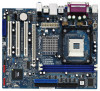
) 1 IR1 Super I/O 4Mb BIOS 7 8 9 FLOPPY1 24.4cm (9.6 in) PCI EXPRESS FSB800 DDR400 1 Top: Line In Center: Line Out Bottom: Mic In 24 23 22 PCIE1 LAN PHY IDE1 IDE2 CMOS Battery CD1 PCI 1 P4VM900-SATA2 PCI 2 VIA VT8237S Audio CODEC 1 HD_AUDIO1 PCI 3 USB2.0 CHA_FAN1 CLRCMOS1 HDMR1 - ASRock P4VM900-SATA2 | User Manual - Page 11
1.5 ASRock 6CH I/O PlusTM 1 2 3 4 5 6 7 12 11 10 1 PS/2 Mouse Port (Green) 2 Parallel Port 3 USB 2.0 Ports (USB23) 4 RJ-45 Port 5 Line In (Light Blue) 6 Line Out (Lime) 9 8 7 Microphone (Pink) 8 Shared USB 2.0 Ports (USB45) 9 USB 2.0 Ports (USB01) 10 VGA Port 11 COM Port 12 PS/2 Keyboard - ASRock P4VM900-SATA2 | User Manual - Page 12
2. Installation P4VM900-SATA2 is a Micro ATX form factor (9.6-in x 8.0-in, 24.4 cm x 20.3 cm) motherboard. Before you install the motherboard, study the configuration of your chassis to ensure that the motherboard fits into it. Pre-installation Precautions Take note of the following precautions - ASRock P4VM900-SATA2 | User Manual - Page 13
Lever Up to 90° CPU Marked Corner Socket Marked Corner STEP 2/STEP 3: Match The CPU Marked Corner to The Socket Marked Corner STEP 4: Push Down And Lock The Socket Lever 2.2 Installation of CPU Fan and Heatsink This motherboard adopts 478-pin CPU socket to support Intel® Pentium® 4 / Celeron - ASRock P4VM900-SATA2 | User Manual - Page 14
2.3 Installation of Memory Modules (DIMM) P4VM900-SATA2 motherboard provides two 184-pin DDR (Double Data Rate break The DIMM only fits in one correct orientation. It will cause permanent damage to the motherboard and the DIMM if you force the DIMM into the slot at incorrect orientation. Step 3. - ASRock P4VM900-SATA2 | User Manual - Page 15
2.4 Expansion Slots (PCI, HDMR and PCI Express Slots) There are 3 PCI slots, 1 HDMR slot, and 1 PCI Express slot on this motherboard. PCI slots: PCI slots are used to install expansion cards that have the 32-bit PCI interface. HDMR slot: The HDMR slot is used to insert a HDMR card with v.92 Modem - ASRock P4VM900-SATA2 | User Manual - Page 16
2.5 Jumpers Setup The illustration shows how jumpers are setup. When the jumper cap is placed on pins, the jumper is "Short". If no jumper cap is placed on pins, the jumper is "Open". The illustration shows a 3-pin jumper whose pin1 and pin2 are "Short" when jumper cap is placed on these 2 pins. - ASRock P4VM900-SATA2 | User Manual - Page 17
one IDE device on this motherboard, please set the IDE device as "Master". Please refer to the instruction of your IDE device vendor for 14) SATAII_2 SATAII_1 These two Serial ATAII (SATAII) connectors support SATAII or SATA hard disk for internal storage devices. The current SATAII interface - ASRock P4VM900-SATA2 | User Manual - Page 18
for the front panel audio cable that allows convenient connection and control of audio devices. 1. High Definition Audio supports Jack Sensing, but the panel wire on the chassis must support HDA to function correctly. Please follow the instruction in our manual and chassis manual to install your - ASRock P4VM900-SATA2 | User Manual - Page 19
BIOS Setup Utility. Enter Advanced Settings, and then select Chipset Configuration. Set the Front Panel Control option from [Auto] to [Enabled]. F. Enter Windows system. Click the icon on the lower right hand taskbar to enter Realtek HD Audio Manager. For Windows® 2000 / XP OS: Click "Audio CPU - ASRock P4VM900-SATA2 | User Manual - Page 20
connector so that it can provides sufficient power. Failing to do so will cause the failure to power up. Please install the heatsink and the CPU fan before installing ATX 12V connector; otherwise, it may cause permanent damage! 20 - ASRock P4VM900-SATA2 | User Manual - Page 21
guide. Some default setting of SATAII hard disks may not be at SATAII mode, which operate with the best performance. In order to enable SATAII function, please follow the below instruction If pin 3 and pin 4 are shorted, SATA 1.5Gb/s will be enabled. On the other .com/hdd/support/download.htm The - ASRock P4VM900-SATA2 | User Manual - Page 22
's SATAII connector. STEP 4: Connect the other end of the SATA data cable to the SATA / SATAII hard disk. 2.9 Hot Plug and Hot Swap Functions for SATA / SATAII HDDs P4VM900-SATA2 motherboard supports Hot Plug and Hot Swap functions for SATA / SATAII Devices. NOTE What is Hot Plug Function? If - ASRock P4VM900-SATA2 | User Manual - Page 23
make sure the SATA / SATAII driver is installed into system properly. The latest SATA / SATAII driver is available on our support website: www.asrock.com 4. Make sure to use the SATA power cable & data cable, which are from our motherboard package. 5. Please follow below instructions step by step - ASRock P4VM900-SATA2 | User Manual - Page 24
follow below instruction sequence to process the Hot Plug, improper procedure will cause the SATA / SATAII HDD damage and data loss. Step 1 Please connect SATA power cable 1x4-pin end Step 2 Connect SATA data cable to (White) to the power supply 1x4-pin cable. the motherboard's SATAII connector - ASRock P4VM900-SATA2 | User Manual - Page 25
RAID functions, please follow below steps. STEP 1: Set up BIOS. A. Enter BIOS SETUP UTILITY Advanced screen IDE Configuration. B. Set the "SATA Operation Mode" option to [RAID]. STEP 2: Make a SATA / SATAII driver diskette. A. Insert the ASRock Support CD into your optical drive to boot your - ASRock P4VM900-SATA2 | User Manual - Page 26
configuration by using the Windows RAID installation guide in the following path in the Support CD: .. \ RAID Installation Guide 2. If you want to use "VIA RAID Tool" in Windows® environment, please install SATA / SATAII drivers from the Support CD again so that "VIA RAID Tool" will be installed - ASRock P4VM900-SATA2 | User Manual - Page 27
to install Windows® 2000 / XP / VistaTM on your system. 2.15 Untied Overclocking Technology This motherboard supports Untied Overclocking Technology, which means during overclocking, FSB enjoys better margin due to fixed PCI / PCIE bus. You may set "CPU Host Frequency" option of BIOS setup to - ASRock P4VM900-SATA2 | User Manual - Page 28
the BIOS SETUP UTILITY to configure your system. The Flash Memory on the motherboard stores the BIOS SETUP UTILITY. You may run the BIOS SETUP off and then back on. Because the BIOS software is constantly being updated, the following BIOS setup screens and descriptions are for reference purpose - ASRock P4VM900-SATA2 | User Manual - Page 29
[16:15:31] [Mon 08/20/2007] BIOS Version : P4VM900-SATA2 BIOS P1.00 Processor Type : Intel (R) CPU 2.80GHz Processor Speed : 2800MHz Microcode Update : F34/17 Cache Size : 256KB Total Memory DDR1 DDR2 : 1024MB with 128MB shared memory : 512MB/166MHz (DDR333) : 512MB/166MHz (DDR333) Use - ASRock P4VM900-SATA2 | User Manual - Page 30
Change Option General Help Load Defaults Save and Exit Exit v02.54 (C) Copyright 1985-2003, American Megatrends, Inc. CPU Host Frequency While entering setup, BIOS auto detects the present CPU host frequency of this motherboard. The actual CPU host frequency will show in the following item. 30 - ASRock P4VM900-SATA2 | User Manual - Page 31
and an operating system that includes optimization for this technology, such as Microsoft® Windows® XP. Set to [Enabled] if using Microsoft® Windows® XP, or Linux kernel version 2.4.18 or higher. This option will be hidden if the installed CPU does not support Hyper-Threading technology. 31 - ASRock P4VM900-SATA2 | User Manual - Page 32
3.3.2 Chipset Configuration BIOS SETUP UTILITY Advanced Chipset Settings DRAM Frequency Flexibility American Megatrends, Inc. DRAM Frequency If [Auto] is selected, the motherboard will detect the memory module(s) inserted and assigns appropriate frequency automatically. You may also select other - ASRock P4VM900-SATA2 | User Manual - Page 33
case of multiple video controllers. The default value of this feature is [PCI]. Configuration options: [Onboard], [PCI] and [PCI Express]. Onboard VGA Share Memory This allows you to set the onboard VGA share memory feature. The default value is [Auto]. Configuration options: [Auto], [16MB], [32MB - ASRock P4VM900-SATA2 | User Manual - Page 34
the onboard HD Audio will be disabled when PCI Sound Card is plugged. Front Panel Select [Auto], [Enabled] or [Disabled] for the onboard HD Audio Front Panel. CD-In Use this item to enable or disable CD-In of OnBoard HD Audio. If you plan to use this motherboard to submit Windows® VistaTM logo test - ASRock P4VM900-SATA2 | User Manual - Page 35
BIOS SETUP UTILITY Advanced ACPI Configuration Suspend To RAM Restore on AC / Power Loss Ring-In Power On PCI Devices disable the Sus pend-to-RAM feature. Select [Auto] will enable this feature if the system supports it. Restore on AC motherboard to submit Windows® VistaTM certification. 35 - ASRock P4VM900-SATA2 | User Manual - Page 36
with Windows® 2000 / XP / VistaTM. Otherwise, please set this item to [non-RAID]. If you install OS on SATA / as the example in the following instruction, which can be applied to the configurations of " ", and "Secondary IDE Slave" as well. BIOS SETUP UTILITY Advanced Primary IDE Master Device Vendor - ASRock P4VM900-SATA2 | User Manual - Page 37
automatically detect the hard disk drive. After selecting the hard disk information into BIOS, use a disk utility, such as FDISK, to partition and format the new the LBA/Large mode for a hard disk > 512 MB under DOS and Windows; for Netware and UNIX user, select [Disabled] to disable the LBA/Large - ASRock P4VM900-SATA2 | User Manual - Page 38
expansion cards' specifications require other settings. PCI IDE BusMaster Use this item to enable or disable the PCI IDE BusMaster feature. 3.3.6 Floppy Configuration In this section, you may configure the type of your floppy drive. BIOS SETUP UTILITY Advanced Floppy Configuration Floppy A Floppy - ASRock P4VM900-SATA2 | User Manual - Page 39
Address Parallel Port Mode EPP Version ECP Mode DMA Channel Parallel Port IRQ [Enabled] [3F8 / IRQ4] [Disabled] [378] [ECP + EPP] [1.9] [DMA3] [IRQ7] Allow BIOS to Enable or Disable Floppy Controller. +F1 F9 F10 ESC Select Screen Select Item Change Option General Help Load Defaults Save and Exit - ASRock P4VM900-SATA2 | User Manual - Page 40
3.3.8 USB Configuration BIOS SETUP UTILITY Advanced USB Configuration USB Controller USB 2.0 Support Legacy USB Support [Enabled] [Enabled] [Disabled] To enable or disable the onboard USB controllers. +F1 F9 F10 ESC Select Screen Select Item Change Option General Help Load Defaults - ASRock P4VM900-SATA2 | User Manual - Page 41
you to monitor the status of the hardware on your system, including the parameters of the CPU temperature, motherboard temperature, CPU fan speed, chassis fan speed, and the critical voltage. BIOS SETUP UTILITY Main Advanced H/W Monitor Boot Security Exit Hardware Health Event Monitoring - ASRock P4VM900-SATA2 | User Manual - Page 42
you may set or change the supervisor/user password for the system. For the user password, you may also clear it. BIOS SETUP UTILITY Main Advanced H/W Monitor Boot Security Exit Security Settings Supervisor Password : Not Installed User Password : Not Installed Change Supervisor Password - ASRock P4VM900-SATA2 | User Manual - Page 43
and exit setup?" Select [OK] to save the changes and exit the BIOS SETUP UTILITY. Discard Changes and Exit When you select this option, it message, "Discard changes and exit setup?" Select [OK] to exit the BIOS SETUP UTILITY without saving any changes. Discard Changes When you select this option - ASRock P4VM900-SATA2 | User Manual - Page 44
install the necessary drivers to activate the devices. 4.2.3 Utilities Menu The Utilities Menu shows the applications software that the motherboard supports. Click on a specific item then follow the installation wizard to install it. 4.2.4 Contact Information If you need to contact ASRock or want to
-
 1
1 -
 2
2 -
 3
3 -
 4
4 -
 5
5 -
 6
6 -
 7
7 -
8
-
9
-
10
-
11
-
12
-
13
-
14
-
15
-
16
-
17
-
18
-
19
-
20
-
21
-
22
-
23
-
24
-
25
-
26
-
27
-
28
-
29
-
30
-
31
-
32
-
33
-
34
-
35
-
36
-
37
-
38
-
39
-
40
-
41
-
42
-
43
-
44
 |
 |

1
P4VM900-SATA2
User Manual
Version 1.0
Published August 2007
Copyright©2007 ASRock INC. All rights reserved.