ASRock P4i45G User Manual
ASRock P4i45G Manual
 |
View all ASRock P4i45G manuals
Add to My Manuals
Save this manual to your list of manuals |
ASRock P4i45G manual content summary:
- ASRock P4i45G | User Manual - Page 1
P4i45G / P4i45GL / P4i45GV User Manual Version 1.1 Published January 2003 Copyright©2003 ASRock INC. All rights reserved. 1 - ASRock P4i45G | User Manual - Page 2
backup purpose, without written consent of ASRock Inc. Products and corporate names appearing in this manual may or may not be registered trademarks benefit, without intent to infringe. Disclaimer: Specifications and information contained in this manual are furnished for informational use only and - ASRock P4i45G | User Manual - Page 3
Contents 1 Introduction 4 1.1 Package Contents 4 1.2 Specifications 5 1.3 Motherboard Layout (P4i45G 8 1.4 Motherboard Layout (P4i45GL 9 1.5 Motherboard Layout (P4i45GV 10 1.6 ASRock I/OTM (P4i45G / P4i45GL / P4i45GV 11 2 Installation 12 2.1 Screw Holes 12 2.2 Pre-installation Precautions - ASRock P4i45G | User Manual - Page 4
website without further notice. ASRock website http://www.asrock.com 1.1 Package Contents ASRock P4i45G or P4i45GL or P4i45GV motherboard (Micro ATX form factor: 9.6" x 9.6", 24.4 x 24.4 cm) ASRock P4i45G / P4i45GL / P4i45GV Quick Installation Guide ASRock Intel-Intel Support CD 1 cable for IDE - ASRock P4i45G | User Manual - Page 5
; CPU fan tachometer; Chassis fan tachometer PCI slots: 3 slots with PCI Specification 2.2 AGP slot (only on P4i45G Motherboard): 1 AGP slot, supports 1.5V, 4X AGP card (see CAUTION 4) AMR slot: 1 slot, supports ASRock MR card (optional) USB 2.0: 4 default USB 2.0 ports and 1 extra set of - ASRock P4i45G | User Manual - Page 6
® XP. It may not work properly under Microsoft® Windows® 98/ME/2000. Please refer to Microsoft® official document at http://www.microsoft.com/HWDEV/BUS/usb/USB2support.asp 6. Although P4i45G / P4i45GL / P4i45GV offers stepless control, it is not recommended to perform over clocking. When the CPU - ASRock P4i45G | User Manual - Page 7
. P4i45G CPU FSB 800 MHz P4i45GL 533 MHz Configuration Note 1. Set the "FSB" jumper to "TEST" mode (see page 15). 2. Only support 1 DDR 333 memory module. Only support DDR 266 memory module. Since the memory types are changing rapidly, please visit ASRock website (http://www.asrock.com/support - ASRock P4i45G | User Manual - Page 8
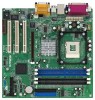
1.3 Motherboard Layout (P4i45G) 22 1 2 1 AUDIO1 PCI LAN Audio CODEC Super I/O AGP 1 PCI 1 PCI 2 P4i45G PCI 3 11 2MB BIOS 5.1CH AMR1 USB2.0 (ATXPWR1) 2 CPU socket 3 CPU fan connector (CPU_FAN1) 4 North Bridge controller 5 184-pin DDR DIMM slots (Blue) 6 168-pin SDRAM DIMM slots - ASRock P4i45G | User Manual - Page 9
1.4 Motherboard Layout (P4i45GL) 22 1 2 1 AUDIO1 PCI LAN Audio CODEC Super I/O PCI 1 PCI 2 P4i45GL PCI 3 11 2MB BIOS 5.1CH AMR1 USB2.0 ATXPWR1) 2 CPU socket 3 CPU fan connector (CPU_FAN1) 4 North Bridge controller 5 184-pin DDR DIMM slots (Blue) 6 168-pin SDRAM DIMM slots - ASRock P4i45G | User Manual - Page 10
1.5 Motherboard Layout (P4i45GV) 22 1 2 1 AUDIO1 PCI LAN Audio CODEC Super I/O PCI 1 PCI 2 P4i45GV PCI 3 11 2MB BIOS 5.1CH AMR1 USB2.0 ATXPWR1) 2 CPU socket 3 CPU fan connector (CPU_FAN1) 4 North Bridge controller 5 184-pin DDR DIMM slots (Blue) 6 168-pin SDRAM DIMM slots - ASRock P4i45G | User Manual - Page 11
1.6 ASRock I/OTM (P4i45G / P4i45GL / P4i45GV) 1 Parallel Port 2 RJ-45 Port 3 Game Port 4 Microphone (Pink) 5 Line In (Light Blue) 6 Line Out (Lime) 7 USB 2.0 Ports 8 VGA Port 9 PS/2 Keyboard Port (Purple) 10 PS/2 Mouse Port (Green) 11 - ASRock P4i45G | User Manual - Page 12
P4i45G / P4i45GL / P4i45GV is a Micro ATX form factor (9.6" x 9.6", 24.4 x 24.4 cm) motherboard. Before you install the motherboard, study the configuration of your chassis to ensure that the motherboard fits into it. Make sure to unplug the power cord before installing or removing the motherboard - ASRock P4i45G | User Manual - Page 13
good contact with each other. For proper installation, please kindly refer to the instruction manuals of the CPU fan and heatsink vendors. 2.5 Installation of Memory Modules (DIMM) SDRAM (Synchronous DRAM) DIMM (Dual In-line Memory Module) has 168 pinsand DDR (Double Data Rate) SDRAM DIMM has 184 - ASRock P4i45G | User Manual - Page 14
, P4i45GL, and P4i45GV motherboards. Additionally, there is 1 AGP slot on P4i45G. PCI slots: PCI slots are used to install expansion cards that have the 32-bit PCI interface. AMR slot: AMR slot is used to insert ASRock MR card with v.92 Modem functionality. AGP slot (only on P4i45G motherboard): The - ASRock P4i45G | User Manual - Page 15
shows a 3-pin jumper whose pin1 and pin2 are "SHORT" when jumper cap is placed on these 2 pins. Jumper FSB (see p.8 item 28) (for P4i45G motherboard only) Setting 1_2 NORMAL 2_3 TEST Description "NORMAL" (short pin1, pin2) is the default setting for the FSB jumper. "TEST" (short pin2, pin3) is - ASRock P4i45G | User Manual - Page 16
Connect this BLUE end to the motherboard 80-Pin ATA 100 cable Connect P+5 GND DUMMY 1 GND P+4 P-4 USB_PWR ASRock I/OTM already provided 4 default USB ports supports an optional wireless transmitting and receiving infrared module. These connectors allow you to receive stereo audio input from sound - ASRock P4i45G | User Manual - Page 17
DUMMY DUMMY +5V This is an interface for front panel audio cable that allows convenient connection and control of audio devices. This connector accommodates several system front panel functions. This DDSR#1 CCTS#1 1 RRI#1 RRTS#1 GND TTXD1 DDCD#1 This COM1 header supports a serial port module. 17 - ASRock P4i45G | User Manual - Page 18
software is constantly being updated, the following BIOS setup screens and descriptions are for reference purpose only, and may not exactly match what you see on your screen. 3.1.1 BIOS Menu Bar The top of the screen has a menu bar with the following selections: MAIN Sets up the basic system - ASRock P4i45G | User Manual - Page 19
Processor Type Processor Speed Cache Size Microcode Update Total Memory DDR1 DDR2 SDR1 SDR2 AMIBIOS SETUP UTILITY - VERSION 3.31a Security Power Boot Exit Jan 08 2003 Wed 20:07:40 [ Setup Help ] Month: Jan - Dec Day: 01 - 31 Year: 1980 - 2099 P4I45G BIOS P1.00 Pentium (R) 4 Family CPU 2100 MHz - ASRock P4i45G | User Manual - Page 20
disk drive that you configured. Below are the configuration options. Main AMIBIOS SETUP UTILITY - VERSION 3.31a Primary IDE Master: [ formatted on an older system, the BIOS Setup may detect incorrect parameters. In these cases, select [User] to manually enter the IDE hard disk drive parameters - ASRock P4i45G | User Manual - Page 21
Maximum Capacity This field shows the drive's maximum capacity as calculated by the BIOS based on the drive information you entered. LBA Mode This allows user to select the LBA mode for a hard disk > 512 MB under DOS and Windows; for Netware and UNIX user, select [Off] to disable the LBA mode. - ASRock P4i45G | User Manual - Page 22
detects installed devices. Install the necessary drivers to activate the devices. 4.2.3 Utilities Menu The Utilities Menu shows the applications software that the motherboard supports. Click on a specific item then follow the installation wizard to install it. 4.2.4 ASRock PC-DIY Live Demo Program - ASRock P4i45G | User Manual - Page 23
Frequency: If [Auto] is selected, the motherboard will detect the memory module(s) inserted and assigns appropriate frequency automatically. You can also select other value as operating frequency: [200MHz], [266MHz]. Hyper-Threading Technology (for P4i45G / P4i45GV only): To enable this feature, it - ASRock P4i45G | User Manual - Page 24
Chipset Configuration [ Setup Help ] AGP Aperture Size ICH Delayed Transaction USB Controller USB Device Legacy Support DRAM CAS Latency 32MB Disabled Disabled Disabled Auto to select the size of mapped memory for graphics data. F1:Help Esc:Previous Menu :Select Item +/-:Change Values - ASRock P4i45G | User Manual - Page 25
the default value unless your PCI expansion cards' specifications require other settings. Primary Graphics Adapter: This OnBoard IDE OnBoard LAN OnBoard AC' 97 Audio OnBoard MC' 97 Modem Auto Auto Auto Enter> to enable or disable the floppy drive controller. F1:Help Esc:Previous Menu :Select Item - ASRock P4i45G | User Manual - Page 26
Audio feature. OnBoard MC'97 Modem: Select [Auto] or [Disabled] for the onboard MC'97 Modem feature. System Hardware Monitor: You can check the status of the hardware on your system. It allows you to monitor the parameters for CPU temperature, Motherboard Setup Menu Main Advanced AMIBIOS SETUP - ASRock P4i45G | User Manual - Page 27
performed before both boot-up and BIOS setup. 3. Power Setup Menu Main Advanced AMIBIOS SETUP UTILITY - Auto] will enable this feature if the system supports it. Repost Video on S3 Resume: This It is recommended to enable this feature under Microsoft® Windows® 98 / ME. Restore on AC/Power Loss: - ASRock P4i45G | User Manual - Page 28
-fields with the actual wake up time you desire. 4. Boot Setup Menu Main Advanced AMIBIOS SETUP UTILITY - VERSION 3.31a Security Power Boot Exit Quick Boot Mode Mode: Enable this mode will speed up the boot-up routine by skipping memory retestings. Boot Up Num-Lock: If this is enabled, it will - ASRock P4i45G | User Manual - Page 29
5. Exit Menu Main Advanced AMIBIOS SETUP UTILITY - VERSION 3.31a Security Power Boot Exit Exit Saving will appear. If you press , it will save the current settings and exit the BIOS SETUP Utility. Exit Discarding Changes: After you enter the submenu, the message "Quit without saving
-
 1
1 -
 2
2 -
 3
3 -
 4
4 -
 5
5 -
 6
6 -
 7
7 -
8
-
9
-
10
-
11
-
12
-
13
-
14
-
15
-
16
-
17
-
18
-
19
-
20
-
21
-
22
-
23
-
24
-
25
-
26
-
27
-
28
-
29
 |
 |

1
P4i45G / P4i45GL / P4i45GV
User Manual
Version 1.1
Published January 2003
Copyright©2003 ASRock INC. All rights reserved.