ASRock P4i45PE R3.0 User Manual
ASRock P4i45PE R3.0 Manual
 |
View all ASRock P4i45PE R3.0 manuals
Add to My Manuals
Save this manual to your list of manuals |
ASRock P4i45PE R3.0 manual content summary:
- ASRock P4i45PE R3.0 | User Manual - Page 1
P4i45PE User Manual Version 3.0 Published October 2003 Copyright©2003 ASRock INC. All rights reserved. 1 - ASRock P4i45PE R3.0 | User Manual - Page 2
duplication of documentation by the purchaser for backup purpose, without written consent of ASRock Inc. Products and corporate names appearing in this manual may or may not be registered trademarks or copyrights of their respective companies, and are used only for identification or explanation and - ASRock P4i45PE R3.0 | User Manual - Page 3
Bar 17 3.2 Main Menu 18 3.3 Advanced, Security, Power, Boot, and Exit Menus ..... 20 4 Software Support 21 4.1 Installing Operating System 21 4.2 Support CD Information 21 4.2.1 Running Support CD 21 4.2.2 Drivers Menu 21 4.2.3 Utilities Menu 21 4.2.4 ASRock "PC-DIY Live Demo" Program 21 - ASRock P4i45PE R3.0 | User Manual - Page 4
the content of this manual will be subject to change without notice. In case any modifications of this manual occur, the updated version Contents ASRock P4i45PE Motherboard (ATX Form Factor: 12.0-in x 7.0-in, 30.5 cm x 17.8 cm) ASRock P4i45PE Quick Installation Guide ASRock P4i45PE Support CD One - ASRock P4i45PE R3.0 | User Manual - Page 5
tachometer; Chassis fan tachometer; Voltage monitoring: +12V, +5V, +3V, Vcore PCI slots: 5 PCI slots with PCI Specification 2.2 AGP slot: 1 AGP slot, supports 1.5V, 4X AGP card (see CAUTION 4) USB 2.0: 4 default USB 2.0 ports and one extra set of header for two ASRock I/OTM: additional USB - ASRock P4i45PE R3.0 | User Manual - Page 6
CAUTION! 1. P4i45PE motherboard may be fine tuned to support higher CPU bus frequencies on certain condition install the PC system. 4. Do NOT plug a 3.3V AGP card in the AGP slot on P4i45PE motherboard! It may cause permanent damage! 5. Power Management for USB 2.0 works fine under Microsoft® - ASRock P4i45PE R3.0 | User Manual - Page 7
memory module on DDR1 DIMM. (If it is set to DDR 400 mode, then it does not support CL3 module.) 3. Update BIOS version to 2.10 or later version. The Recommended Memory Modules lists for P4i45PE motherboard. FSB 800 MHz / DDR 400 Mode DRAM SIZE TYPE CELL VENDOR (MB) VENDOR ADATA ADATA ADATA - ASRock P4i45PE R3.0 | User Manual - Page 8
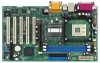
2.0 Ports 26 25 24 23 22 GGAAMMEE AAUUDDIIOO11 USB 2.0 Ports Line out LiLInnineein MMIniicc in AUX1 CD1 1 AUDIO1 JR1 JL1 AUDIO CODEC Intel 845PE Chipset P4i45PE 1.5V_AGP1 DDR1 (64/72 bit, 184-pin module) DDR2 (64/72 bit, 184-pin module) 30.5cm (12.0 in) 8 9 IDE2 IDE1 10 PCI 1 21 20 - ASRock P4i45PE R3.0 | User Manual - Page 9
1.4 ASRock I/OTM 1 2 3 10 9 1 Parallel Port 2 RJ-45 Port 3 Game Port 4 Microphone (Pink) 5 Line In (Light Blue) 8 7 65 4 6 Line Out (Lime) 7 USB 2.0 Ports 8 Serial Port (COM1) 9 PS/2 Keyboard Port (Purple) 10 PS/2 Mouse Port (Green) 9 - ASRock P4i45PE R3.0 | User Manual - Page 10
Chapter 2 Installation P4i45PE is an ATX form factor (12.0-in x 7.0-in, 30.5 cm x 17.8 cm) directly on the carpet or the like. Also remember to use a grounded wrist strap or touch a safety grounded object before you handle components. 3. Hold components by the edges and do not touch the ICs. - ASRock P4i45PE R3.0 | User Manual - Page 11
with each other. Then connect the CPU fan to the CPU_FAN connector (CPU_FAN1, see page 8, No. 27). For proper installation, please kindly refer to the instruction manuals of the CPU fan and heatsink vendors. 11 - ASRock P4i45PE R3.0 | User Manual - Page 12
2.5 Installation of Memory Modules (DIMM) P4i45PE motherboard provides two 184-pin DDR (Double Data Rate) DIMM slots. Please make sure to disconnect power supply before adding or removing DIMMs or the - ASRock P4i45PE R3.0 | User Manual - Page 13
special locking mechanism which can securely fasten the graphics card inserted. Please do not plug a 3.3V AGP card in the AGP slot on P4i45PE motherboard! It may cause permanent damage! Installing an expansion card Step 1. Before installing the expansion card, please make sure that the power supply - ASRock P4i45PE R3.0 | User Manual - Page 14
2.7 Jumpers Setup The illustration shows how jumpers are setup. When the jumper cap is placed on pins, the jumper is "Short". If no jumper cap is placed on pins, the jumper is "Open". The illustration shows a 3-pin jumper whose pin1 and pin2 are "Short" when jumper cap is placed on these 2 pins. - ASRock P4i45PE R3.0 | User Manual - Page 15
please set the IDE device as "Master". Please refer to the instruction of your IDE device vendor for the details. Besides, to optimize the rear USB ports are not sufficient, this header is available to support 2 additional USB 2.0 ports. Infrared module connector (5-pin IR1) (see p.8 item - ASRock P4i45PE R3.0 | User Manual - Page 16
Internal audio connectors (4-pin CD1, 4-pin AUX1) (CD1: see p.8 item 26) (AUX1: see p.8 item 25) AUX-L GND GND AUX-R AUX1 CD-L GND GND CD-R CD1 These connectors allow you to receive stereo audio input from sound sources such as a CD-ROM, DVD-ROM, TV tuner card, or MPEG card. Front panel audio - ASRock P4i45PE R3.0 | User Manual - Page 17
Chapter 3 BIOS Setup 3.1 BIOS Setup Utility This section explains how to configure your system using the BIOS Setup Utility. The BIOS FWH chip on the motherboard stores the BIOS Setup Utility. When you start up the computer, there is a chance for you to run the BIOS Setup. Press during the - ASRock P4i45PE R3.0 | User Manual - Page 18
UTILITY - VERSION 3.31a Security Power Boot Exit Oct 07 2003 Tue 16:07:40 [ Setup Help ] Month: Jan - Dec Day: 01 - 31 Year: 1980 - 2099 P4I45PE BIOS P2.10 Pentium (R) 4 CPU 2400 MHz 512 KB F24 / 18 256 MB 256 MB / 133 MHz (DDR266) None F1:Help Esc:Exit :Select Item - ASRock P4i45PE R3.0 | User Manual - Page 19
new. If the hard disk was already formatted on an older system, the BIOS Setup may detect incorrect parameters. In these cases, select [User] to manually enter the IDE hard disk drive parameters. After entering the hard disk information into BIOS, use a disk utility, such as FDISK, to partition and - ASRock P4i45PE R3.0 | User Manual - Page 20
[CD/DVD]: This is used for IDE CD/DVD drives. [ARMD]: This is used for IDE ARMD (ATAPI Removable Media Device), such as MO. Cylinders This is used to configure the number of cylinders. Refer to the drive documentation to determine the correct value. Heads This is used to configure the number of read - ASRock P4i45PE R3.0 | User Manual - Page 21
computer. If the Main Menu did not appear automatically, locate and double click on the file ASSETUP.EXE from the BIN folder in the Support CD to display the menus. 4.2.2 Drivers Menu The Drivers Menu shows the available devices drivers if the system detects installed devices. Install the necessary - ASRock P4i45PE R3.0 | User Manual - Page 22
the operating frequency. Hyper Threading Technology: To enable this feature, it requires a computer system with an Intel Pentium®4 processor that supports Hyper-Threading Technology and an operating system that includes optimization for this technology, such as Microsoft® Windows® XP. Set to [Auto - ASRock P4i45PE R3.0 | User Manual - Page 23
and LPC interface accesses. USB Controller: Use this to enable or disable the use of USB controller. USB Device Legacy Support: Use this to enable or disable support to emulate legacy I/O devices such as mouse, keyboard,... etc. CPU Thermal Throttling: Select [Enabled] will enable P4 thermal control - ASRock P4i45PE R3.0 | User Manual - Page 24
Configure SDRAM Timing by SPD: Select [Enabled] will configure the following 3 items by the contents in the SPD (Serial Presence Detect) device. SDRAM RAS# Precharge: This controls the idle clocks after a precharge command is issued. SDRAM RAS# to CAS# Delay: This controls the latency between the - ASRock P4i45PE R3.0 | User Manual - Page 25
Peripheral Configuration: Advanced AMIBIOS SETUP UTILITY - VERSION 3.31a Peripheral Configuration [ Setup Help ] OnBoard FDC OnBoard Serial Port OnBoard Infrared Port OnBoard Parallel Port Parallel Port Mode EPP Version Parallel Port IRQ Parallel Port DMA Channel OnBoard Midi Port Midi IRQ - ASRock P4i45PE R3.0 | User Manual - Page 26
OnBoard LAN: This allows you to enable or disable the on-board LAN feature. OnBoard AC'97 Audio: Select [Enabled], [Auto] or [Disabled] for the on-board AC'97 Audio feature. System Hardware Monitor: You may check the status of the hardware on your system. It allows you to monitor the parameters for - ASRock P4i45PE R3.0 | User Manual - Page 27
2. Security Setup Menu Main Advanced AMIBIOS SETUP UTILITY - VERSION 3.31a Security Power Boot Exit Supervisor Password Is User Password Is Set Supervisor Password Set User Password Clear Clear [ Enter ] [ Enter ] [ Setup Help ] to enable or disable the quick boot mode. Password Check - ASRock P4i45PE R3.0 | User Manual - Page 28
allows you to select whether to auto-detect or disable the ACPI Suspend-to-RAM feature. Select [Auto] will enable this feature if the system supports it. Repost Video on STR Resume: This feature allows you to repost video on STR resume. It is recommended to enable this feature under Microsoft - ASRock P4i45PE R3.0 | User Manual - Page 29
4. Boot Setup Menu Main Advanced AMIBIOS SETUP UTILITY - VERSION 3.31a Security Power Boot Exit Quick Boot Mode Boot Up Num-Lock Boot To OS/2 Boot From Network Enabled On No Disabled [ Setup Help ] to enable or disable the quick boot mode. Boot Device Priority F1:Help Esc:Exit : - ASRock P4i45PE R3.0 | User Manual - Page 30
5. Exit Menu Main Advanced AMIBIOS SETUP UTILITY - VERSION 3.31a Security Power Boot Exit Exit Saving Changes Exit Discarding Changes Load Default Settings Discard Changes [ Enter ] [ Enter ] [ Enter ] [ Enter ] [ Setup Help ] Exits and saves the changes in CMOS RAM. F1:Help Esc:Exit :Select
-
 1
1 -
 2
2 -
 3
3 -
 4
4 -
 5
5 -
 6
6 -
 7
7 -
8
-
9
-
10
-
11
-
12
-
13
-
14
-
15
-
16
-
17
-
18
-
19
-
20
-
21
-
22
-
23
-
24
-
25
-
26
-
27
-
28
-
29
-
30
 |
 |

1
P4i45PE
User Manual
Version 3.0
Published October 2003
Copyright©2003 ASRock INC. All rights reserved.