ASRock P4i48 User Manual
ASRock P4i48 Manual
 |
View all ASRock P4i48 manuals
Add to My Manuals
Save this manual to your list of manuals |
ASRock P4i48 manual content summary:
- ASRock P4i48 | User Manual - Page 1
P4i48 User Manual Version 1.0 Published February 2004 Copyright©2004 ASRock INC. All rights reserved. 1 - ASRock P4i48 | User Manual - Page 2
any form or by any means, except duplication of documentation by the purchaser for backup purpose, without written consent of ASRock Inc. Products and corporate names appearing in this manual may or may not be registered trademarks or copyrights of their respective companies, and are used only for - ASRock P4i48 | User Manual - Page 3
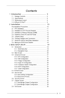
1.1 Package Contents 5 1.2 Specifications 6 1.3 Motherboard Layout 8 1.4 ASRock I/O PlusTM 9 2 Installation 10 Pre-installation Disks Installation 18 2.8 Making An SATA Driver Diskette 18 3 BIOS SETUP UTILITY 19 3.1 Introduction 19 3.1.1 BIOS Menu Bar 19 3.1.2 Navigation Keys 20 - ASRock P4i48 | User Manual - Page 4
4 Software Support 36 4.1 Install Operating System 36 4.2 Support CD Information 36 4.2.1 Running Support CD 36 4.2.2 Drivers Menu 36 4.2.3 Utilities Menu 36 4.2.4 ASRock "PC-DIY Live Demo" Program 36 4.2.5 Contact Information 36 4 - ASRock P4i48 | User Manual - Page 5
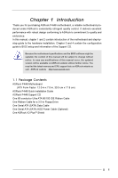
guide to BIOS setup and information of the Support CD. Because the motherboard specifications and the BIOS software might be updated, the content of this manual will be subject to change without notice. In case any modifications of this manual occur, the updated version will be available on ASRock - ASRock P4i48 | User Manual - Page 6
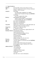
) Floppy Port: Supports up to 2 floppy disk drives Audio: 5.1 channels AC'97 Audio PCI LAN: Speed: 802.3u (10/100 Ethernet), supports Wake-On-LAN Hardware Monitor: CPU temperature sensing, Chassis temperature sensing, CPU overheat shutdown to protect CPU life (ASRock U-COP)(see CAUTION - ASRock P4i48 | User Manual - Page 7
frequency and its corresponding CPU FSB frequency. CPU FSB Frequency Memory Support Frequency 800 DDR266, DDR320*, DDR400 533 DDR266, DDR333 400 DDR266 * When you use an FSB800-CPU on this motherboard, it will run at DDR320 if you adopt a DDR333 memory module. 3. While CPU overheat - ASRock P4i48 | User Manual - Page 8
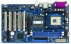
1.3 Motherboard Layout 12 34 5 6 17.8cm (7.0 in) PS2 Mouse PS2 Keyboard T: USB4 1 B: USB5 USB4_5 AUX1 CD1 1 AUDIO1 JR1 JL1 AUDIO CODEC 22 21 PCI LAN Super I/O 2MB BIOS 1 Intel 848 Chipset IDE2 IDE1 1.5V_AGP1 P4i48 PCI 1 FSB800DDR400 PCI 2 USB2.0 AGP8X Intel ICH5 PCI 3 5. - ASRock P4i48 | User Manual - Page 9
1.4 ASRock I/O PlusTM 1 11 10 9 1 Parallel Port 2 RJ-45 Port 3 Line In (Light Blue) 4 Line Out (Lime) 5 Microphone (Pink) 6 Shared USB 2.0 Ports (USB45) 2 3 4 5 8 7 6 7 USB 2.0 Ports (USB01) 8 USB 2.0 - ASRock P4i48 | User Manual - Page 10
P4i48 is an ATX form factor (12.0-in x 7.0-in, 30.5 cm x 17.8 cm) motherboard. Before you install the motherboard, study the configuration of your chassis to ensure that the motherboard fits into it. Pre-installation Precautions Take note of the following precautions before you install motherboard - ASRock P4i48 | User Manual - Page 11
And Lock The Socket Lever 2.2 Installation of CPU Fan and Heatsink This motherboard adopts 478-pin CPU socket to support Intel® Pentium®4 CPU. It requires larger heatsink and cooling fan to For proper installation, please kindly refer to the instruction manuals of the CPU fan and the heatsink. 11 - ASRock P4i48 | User Manual - Page 12
2.3 Installation of Memory Modules (DIMM) P4i48 motherboard provides two 184-pin DDR (Double Data Rate) break The DIMM only fits in one correct orientation. It will cause permanent damage to the motherboard and the DIMM if you force the DIMM into the slot at incorrect orientation. Step 3. Firmly - ASRock P4i48 | User Manual - Page 13
AGP Slots) There are 5 PCI slots and 1 AGP slot on P4i48 motherboard. PCI slots: PCI slots are used to install expansion cards that have the 32-bit PCI interface. AGP slot: The AGP slot is used to install a graphics card. The ASRock AGP slot has a special locking mechanism which can securely fasten - ASRock P4i48 | User Manual - Page 14
Note: If the jumpers JL1 and JR1 are short, both the front panel and the rear panel audio connectors can work. Clear CMOS (CLRCMOS0, 2-pin jumper) (see p.8 No. 14) 2-pin need to clear the CMOS when you just finish updating the BIOS, you must boot up the system first, and then shut it down - ASRock P4i48 | User Manual - Page 15
to the IDE devices 80-conductor ATA 66/100 cable Note: If you use only one IDE device on this motherboard, please set the IDE device as "Master". Please refer to the instruction of your IDE device vendor for the details. Besides, to optimize compatibility and performance, please connect your hard - ASRock P4i48 | User Manual - Page 16
the connector on each drive. Then powersupply connect USB 2.0 ports 4,5 on ASRock I/O PlusTM. When using the supports an optional wireless transmitting and receiving infrared module. AUX-L GND GND AUX-R AUX1 CD-L GND GND CD-R CD1 These connectors allow you to receive stereo audio input from sound - ASRock P4i48 | User Manual - Page 17
System Panel Header (9-pin PANEL1) (see p.8 No. 17) Chassis Speaker Header (4-pin SPEAKER 1) (see p.8 No. 16) Chassis Fan Connector (3-pin CHA_FAN1) (see p.8 No. 11) CPU Fan Connector (3-pin CPU_FAN1) (see p.8 No. 29) ATX Power Connector (20-pin ATXPWR1) (see p.8 No. 6) PLED+ PLEDPWRBTN# GND 1 - ASRock P4i48 | User Manual - Page 18
supports Serial ATA (SATA) hard disks. You may install SATA hard disks on this motherboard for internal storage devices. This section will guide you to install the SATA hard disks. STEP 1: Install the SATA hard disks into the drive the motherboard's BIOS setup is correct according to the condition - ASRock P4i48 | User Manual - Page 19
the BIOS SETUP UTILITY to configure your system. The BIOS FWH chip on the motherboard stores the BIOS SETUP UTILITY. You may run the BIOS SETUP off and then back on. Because the BIOS software is constantly being updated, the following BIOS setup screens and descriptions are for reference purpose - ASRock P4i48 | User Manual - Page 20
Overview System Time System Date [14:00:09] [Tue 01/13/2004] BIOS Version : P4i48 BIOS P1.00 Processor Type : Intel (R) Pentium (R) 4 CPU 2.40 GHz Processor Speed : 2400 MHz Cache Size : 512KB Microcode Update : 0F29/17 Total Memory DIMM 1 DIMM 2 : 256MB : 256MB/166MHz (DDR333) : None Use - ASRock P4i48 | User Manual - Page 21
cause the system to malfunction. 3.3.1 CPU Configuration Advanced BIOS SETUP UTILITY CPU Configuration CPU Host Frequency Actual Frequency Inc. CPU Host Frequency While entering setup, BIOS auto detects the present CPU host frequency of this motherboard. The actual CPU host frequency will show - ASRock P4i48 | User Manual - Page 22
appears to allow you changing the ratio value of this motherboard. If it shows "Locked", then the item Ratio CMOS supports Hyper-Threading technology and an operating system that includes optimization for this technology, such as Microsoft® Windows® XP. Set to [Auto] if using Microsoft® Windows - ASRock P4i48 | User Manual - Page 23
3.3.2 IDE Configuration Advanced BIOS SETUP UTILITY IDE Configuration OnBoard IDE Operate Mode is set to [SATA + Sec IDE], then the primary IDE will not work. Because legacy OS (Windows ME / 98SE) only supports four IDE devices, you have to choose either [Pri IDE + SATA] or [SATA + Sec IDE] - ASRock P4i48 | User Manual - Page 24
as the example in the following instruction, which can be applied to the .0 GB :Supported :16Sectors :4 :MultiWord DMA-2 :Ultra DMA-5 :Supported [Auto] drive. After selecting the hard disk information into BIOS, use a disk utility, such as FDISK, to partition and format the new IDE hard disk drives - ASRock P4i48 | User Manual - Page 25
32-bit access to maximize the IDE hard disk data transfer rate. 3.3.3 Floppy Configuration In this section, you may configure the type of your floppy drive. BIOS SETUP UTILITY Advanced Floppy Configuration Floppy A Floppy B [1.44 MB 312"] [Disabled] Select the type of floppy - ASRock P4i48 | User Manual - Page 26
378] [ECP + EPP] [1.9] [DMA3] [IRQ7] [Enabled] [Disabled] Allow BIOS to Enable or Disable Floppy Controller. +F1 F9 F10 ESC Select Screen Select Item Inc. OnBoard Floppy Controller Use this item to enable or disable floppy drive controller. Serial Port Address Use this item to set the address for - ASRock P4i48 | User Manual - Page 27
CPU temperature, motherboard temperature, CPU fan speed, chassis fan speed, and the critical voltage. Advanced BIOS SETUP UTILITY Hardware 2003, American Megatrends, Inc. 3.3.6 ACPI Configuration Advanced BIOS SETUP UTILITY ACPI Settings Suspend To RAM Restore on AC / Power Loss Ring-In Power - ASRock P4i48 | User Manual - Page 28
RAM Use this item to select whether to auto-detect or disable the Suspend-toRAM feature. Select [Auto] will enable this feature if the OS supports USB Configuration BIOS SETUP UTILITY Advanced USB Configuration USB Devices Enabled : None USB Controller USB 2.0 Support Legacy USB Support [Enabled] - ASRock P4i48 | User Manual - Page 29
connected, "Auto" option will disable the legacy USB support. 3.4 PCIPnP Screen In this section, you may configure the PCI Latency Timer and the PCI IDE Bus Master. Main Advanced BIOS SETUP UTILITY PCIPnP Boot Security Chipset Exit Advanced PCI / PnP Settings - ASRock P4i48 | User Manual - Page 30
to configure the boot settings and the boot priority. BIOS SETUP UTILITY Main Advanced PCIPnP Boot Security Chipset Exit Boot Settings Boot Settings Configuration Boot Device Priority Hard Disk Drives Removable Drives CD / DVD Drives Configure Settings during System Boot. Select Screen Select - ASRock P4i48 | User Manual - Page 31
In this section, you may specify the boot sequence from the available devices in your system. BIOS SETUP UTILITY Boot Boot Device Priority 1st Boot Device 2nd Boot Device 3rd Boot Device [1st FLOPPY DRIVE] [HDD: PM-MAXTOR 6L08] [CD / DVD] Specifies the boot sequence from the available devices - ASRock P4i48 | User Manual - Page 32
the south bridge Chipset. BIOS SETUP UTILITY Main Advanced [64MB] Chipset Options 133MHz 166MHz 200MHz Auto (DDR266) (DDR333) (DDR400) +F1 F9 F10 ESC Select Screen Select Item Change Option General Frequency If [Auto] is selected, the motherboard will detect the memory module(s) inserted and - ASRock P4i48 | User Manual - Page 33
Configure DRAM Timing by SPD Select [Enabled] will configure the following items by the contents in the SPD (Serial Presence Detect) device. DRAM CAS# Latency Use this item to adjust the means of memory accessing. Configuration options: [Auto], [2.5], [2], and [3]. DRAM RAS# Precharge This controls - ASRock P4i48 | User Manual - Page 34
3.7.2 SouthBridge Chipset Configuration BIOS SETUP UTILITY SouthBridge Chipset Configuration Onboard LAN Onboard AC97 Audio [Enabled] [Auto] Chipset Enable / Disable onboard LAN. +F1 F9 F10 ESC Select Screen Select Item Change Option General Help Load Defaults Save and Exit Exit - ASRock P4i48 | User Manual - Page 35
and exit setup?" Select [OK] to save the changes and exit the BIOS SETUP UTILITY. Discard Changes and Exit When you select this option, it message, "Discard changes and exit setup?" Select [OK] to exit the BIOS SETUP UTILITY without saving any changes. Discard Changes When you select this option - ASRock P4i48 | User Manual - Page 36
for more information. 4.2 Support CD Information The Support CD that came with the motherboard contains necessary drivers and useful utilities that enhance the motherboard features. 4.2.1 Running The Support CD To begin using the support CD, insert the CD into your CD-ROM drive. The CD automatically
-
 1
1 -
 2
2 -
 3
3 -
 4
4 -
 5
5 -
 6
6 -
 7
7 -
8
-
9
-
10
-
11
-
12
-
13
-
14
-
15
-
16
-
17
-
18
-
19
-
20
-
21
-
22
-
23
-
24
-
25
-
26
-
27
-
28
-
29
-
30
-
31
-
32
-
33
-
34
-
35
-
36
 |
 |

1
P4i48
User Manual
Version 1.0
Published February 2004
Copyright©2004 ASRock INC. All rights reserved.