ASRock P4i65G User Manual
ASRock P4i65G Manual
 |
View all ASRock P4i65G manuals
Add to My Manuals
Save this manual to your list of manuals |
ASRock P4i65G manual content summary:
- ASRock P4i65G | User Manual - Page 1
P4i65G User Manual Version 1.3 Published November 2006 Copyright©2006 ASRock INC. All rights reserved. 1 - ASRock P4i65G | User Manual - Page 2
without written consent of ASRock Inc. Products and corporate names appearing in this manual may or may not be intent to infringe. Disclaimer: Specifications and information contained in this manual are furnished for informational use battery adopted on this motherboard contains Perchlorate, a toxic - ASRock P4i65G | User Manual - Page 3
Introduction 5 1.1 Package Contents 5 1.2 Specifications 6 1.3 Motherboard Layout 9 1.4 ASRock I/O PlusTM 10 2 Installation 11 Pre-installation Precautions 11 2.1 CPU Installation 12 2.2 Installation of CPU Fan and Heatsink 12 2.3 Installation of Memory Modules (DIMM 13 2.4 Expansion Slots - ASRock P4i65G | User Manual - Page 4
4 Software Support 36 4.1 Install Operating System 36 4.2 Support CD Information 36 4.2.1 Running Support CD 36 4.2.2 Drivers Menu 36 4.2.3 Utilities Menu 36 4.2.4 Contact Information 36 4 - ASRock P4i65G | User Manual - Page 5
modifications of this manual occur, the updated version will be available on ASRock website without further notice. You may find the latest VGA cards and CPU support lists on ASRock website as well. ASRock website http://www.asrock.com 1.1 Package Contents ASRock P4i65G Motherboard (Micro ATX Form - ASRock P4i65G | User Manual - Page 6
1.2 Specifications Platform CPU Chipset Memory Hybrid Booster Expansion Slot Graphics Audio LAN Rear Panel I/O - Micro ATX Form Factor: 9.6-in x 7.8-in, 24.4 cm x 19.8 cm - Socket 478 for Intel® Pentium® 4 / Celeron® D (Prescott, Northwood, Willamate) processors - FSB 800/533/400 MHz - Supports - ASRock P4i65G | User Manual - Page 7
header - CPU/Chassis FAN connector - 20 pin ATX power connector - 4 pin 12V power connector - CD in header - AUX in header - Front panel audio connector - 2 x USB 2.0 headers (support 4 USB 2.0 ports; 2 of them are shared with USB4_5) (see CAUTION 8) - 4Mb AMI BIOS - AMI Legal BIOS - Supports "Plug - ASRock P4i65G | User Manual - Page 8
CPU and the heatsink when you install the PC system. 7. Do NOT use a 3.3V AGP card on the AGP slot of this motherboard! It may cause permanent damage! 8. Power Management for USB 2.0 works fine under Microsoft® Windows® XP SP1 or SP2 / 2000 SP4. It may not work properly under Microsoft® Windows® 98 - ASRock P4i65G | User Manual - Page 9
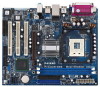
USB 2.0 1 T: USB4 B: USB5 CD1 Intel 865G Chipset AUDIO1 AUX1 1 JR1 JL1 AUDIO CODEC PCI LAN 1.5V_AGP1 PCI 1 AGP8X Super I/O 1 COM1 4Mb BIOS PCI 2 RoHS FSB800 SATA USB2.0 5.1CH PCI 3 FLOPPY1 AMR1 IDE2 IDE1 Intel ICH5 CMOS Battery CLRCMOS0 SATA2 SATA1 USB67 1 IR1 1 CHA_FAN1 PANEL - ASRock P4i65G | User Manual - Page 10
1.4 ASRock I/O PlusTM 1 11 10 9 1 Parallel Port 2 RJ-45 Port 3 Line In (Light Blue) 4 Line Out (Lime) 5 Microphone (Pink) 6 Shared USB 2.0 Ports (USB45) 2 3 4 5 8 7 6 7 USB 2.0 Ports (USB01) 8 USB 2.0 Ports (USB23) 9 VGA Port 10 PS/2 Keyboard Port (Purple) 11 PS/2 Mouse Port (Green) 10 - ASRock P4i65G | User Manual - Page 11
Precautions Take note of the following precautions before you install motherboard components or change any motherboard settings. 1. Unplug the power cord from the wall socket before touching any component. 2. To avoid damaging the motherboard components due to static electricity, NEVER place your - ASRock P4i65G | User Manual - Page 12
Lever Up to 90° STEP 2/STEP 3: Match The CPU Marked Corner to The Socket Marked Corner STEP 4: Push Down And Lock The Socket Lever 2.2 Installation of CPU Fan and Heatsink This motherboard adopts 478-pin CPU socket to support Intel® Pentium®4 CPU. It requires larger heatsink and cooling fan to - ASRock P4i65G | User Manual - Page 13
2.3 Installation of Memory Modules (DIMM) This motherboard provides two 184-pin DDR (Double Data Rate) DIMM slots, and supports Dual Channel Memory Technology. For dual channel configuration, you always need to install two identical (the same brand, speed, size and chip-type) memory modules in the - ASRock P4i65G | User Manual - Page 14
fasten the inserted graphics card. Do NOT use a 3.3V AGP card on the AGP slot of this motherboard! It may cause permanent damage! AMR slot: AMR slot is used to insert an ASRock MR card (optional) with v.92 Modem functionality. Installing an expansion card Step 1. Before installing the expansion card - ASRock P4i65G | User Manual - Page 15
+5VSB or USB wake up events. Note: To select +5VSB, it requires 2 Amp and higher standby current provided by power supply. JR1(see p.9 No. 25) JL1(see p.9 No. 25) JR1 JL1 Note: If the jumpers JL1 and JR1 are short, both the front panel and the rear panel audio connectors can work. Clear CMOS - ASRock P4i65G | User Manual - Page 16
ATA (SATA) connectors support SATA data cables for internal storage devices. The current SATA interface allows up to 1.5 Gb/s data transfer rate. Serial ATA (SATA) Data Cable Either end of the SATA data cable can be connected to the SATA hard disk or the SATA connector on the motherboard. 16 - ASRock P4i65G | User Manual - Page 17
AUX-L GND GND AUX-R This header supports an optional wireless transmitting and receiving infrared module. These connectors allow you to receive stereo audio input from sound sources such as a CD-ROM, DVD-ROM, TV tuner card, or MPEG card. Front Panel AC'97 Audio Header (8-pin AUDIO1) (see p.9 No - ASRock P4i65G | User Manual - Page 18
to any other power, such as USB. 2. HD (Azalia) audio front panel and AC'97 audio front panel have different pin-definition. Incorrect connection of the audio front panel and the front panel audio header may cause permanent damage to this motherboard. System Panel Header (9-pin PANEL1) (see p.9 No - ASRock P4i65G | User Manual - Page 19
, please refer to the instruction on page 27. 2.8 Untied Overclocking Technology This motherboard supports Untied Overclocking Technology, which means during overclocking, FSB enjoys better margin due to fixed AGP / PCI bus. You may set "CPU Host Frequency" option of BIOS setup to [Auto], which - ASRock P4i65G | User Manual - Page 20
by pressing + + , or by pressing the reset button on the system chassis. You may also restart by turning the system off and then back on. Because the BIOS software is constantly being updated, the following BIOS setup screens and descriptions are for reference purpose only, and - ASRock P4i65G | User Manual - Page 21
Advanced BIOS SETUP UTILITY H/W Monitor Boot System Overview System Time System Date [14:00:09] [Tue 02/21/2006] BIOS Version : P4i65G BIOS P1.00 Processor Type : Intel (R) Pentium (R) 4 CPU 2.40 GHz Processor Speed : 2400 MHz Microcode Update : F24/1E Cache Size : 512KB Total Memory - ASRock P4i65G | User Manual - Page 22
and Exit Exit v02.54 (C) Copyright 1985-2003, American Megatrends, Inc. CPU Host Frequency While entering setup, BIOS auto detects the present CPU host frequency of this motherboard. The actual CPU host frequency will show in the following item. Boot Failure Guard Enable or disable the feature of - ASRock P4i65G | User Manual - Page 23
to keep the CPU from overheated. Hyper Threading Technology To enable this feature, it requires a computer system with an Intel Pentium®4 processor that supports Hyper-Threading technology and an operating system that includes optimization for this technology, such as Microsoft® Windows® XP. Set to - ASRock P4i65G | User Manual - Page 24
Chipset Configuration BIOS SETUP UTILITY Advanced Chipset Configuration [PCI / AGP] [Auto] OnBoard LAN OnBoard AC'97 Audio OnBoard MC'97 Modem [Enabled] [Auto] [Auto] Options If [Auto] is selected, the motherboard will detect the memory module(s) inserted and assigns appropriate frequency - ASRock P4i65G | User Manual - Page 25
will not appear if there is no AGP VGA card installed on this motherboard. It refers to a section of the PCI memory address range used for graphics memory. It is recommended to leave this field at the default value unless the installed AGP card's specifications requires other sizes. OnBoard LAN This - ASRock P4i65G | User Manual - Page 26
3.3.3 ACPI Configuration BIOS SETUP UTILITY Advanced ACPI Configuration Suspend To RAM Restore on AC / the power recovers. If [Power On] is selected, the AC/Power resumes and the system starts to boot up when the power recovers. Ring-In Power On Use this item to enable or disable Ring-In signals - ASRock P4i65G | User Manual - Page 27
. Likewise, if it is set to [SATA + Sec IDE], then the primary IDE will not work. Because Intel® ICH5 south bridge only supports four IDE devices under legacy OS (Windows ME / 98SE), you have to choose either [Pri IDE + SATA] or [SATA + Sec IDE] when the installed SATA device is used with legacy OS - ASRock P4i65G | User Manual - Page 28
instruction, Supported :16Sectors :4 :MultiWord DMA-2 :Ultra DMA-5 :Supported information into BIOS, use CD/DVD drives. [ARMD]: This is used for IDE ARMD (ATAPI Removable Media Device), such as MO. LBA/Large Mode Use this item to select the LBA/Large mode for a hard disk > 512 MB under DOS and Windows - ASRock P4i65G | User Manual - Page 29
to maximize the IDE hard disk data transfer rate. 3.3.5 PCIPnP Configuration BIOS SETUP UTILITY Advanced PCI / PnP Configuration PCI Latency Timer PCI IDE default value unless the installed PCI expansion cards' specifications require other settings. PCI IDE BusMaster Use this item to enable - ASRock P4i65G | User Manual - Page 30
Load Defaults Save and Exit Exit v02.54 (C) Copyright 1985-2003, American Megatrends, Inc. 3.3.7 Super IO Configuration BIOS SETUP UTILITY Advanced Configure Super IO Chipset OnBoard Floppy Controller Serial Port Address Infrared Port Address Parallel Port Address Parallel Port Mode EPP Version - ASRock P4i65G | User Manual - Page 31
parallel port. Configuration options: [IRQ5] and [IRQ7]. 3.3.8 USB Configuration BIOS SETUP UTILITY Advanced USB Configuration USB Controller USB 2.0 Support Legacy USB Support [Enabled] [Enabled] [Disabled] To enable or disable the onboard USB controllers. +F1 F9 F10 ESC Select Screen Select - ASRock P4i65G | User Manual - Page 32
motherboard temperature, CPU fan speed, chassis fan speed, and the critical voltage. BIOS SETUP UTILITY Main Advanced H/W Monitor Boot Security Exit Hardware Health Event Monitoring CPU Temperature M / B Temperature CPU Fan Speed Chassis Fan Speed Vcore + 3.30V + 5.00V + 12.00V : 45 C / 98 - ASRock P4i65G | User Manual - Page 33
on your system for you to configure the boot settings and the boot priority. Main Advanced BIOS SETUP UTILITY H/W Monitor Boot Security Exit Boot Settings Boot Settings Configuration Boot Device Priority Hard Disk Drives Removable Drives CD / DVD Drives Configure Settings during System - ASRock P4i65G | User Manual - Page 34
, the removable drives, and the CD/DVD drives. 3.6 Security Screen In this section, you may set or change the supervisor/user password for the system. For the user password, you may also clear it. BIOS SETUP UTILITY Main Advanced H/W Monitor Boot Security Exit Security Settings Supervisor - ASRock P4i65G | User Manual - Page 35
3.7 Exit Screen Main BIOS SETUP UTILITY Advanced H/W Monitro Boot Security Exit Exit Options Save Changes and "Save configuration changes and exit setup?" Select [OK] to save the changes and exit the BIOS SETUP UTILITY. Discard Changes and Exit When you select this option, it will pop-out the - ASRock P4i65G | User Manual - Page 36
2000 / XP. Because motherboard settings and hardware options vary, use the setup procedures in this chapter for general reference only. Refer to your OS documentation for more information. 4.2 Support CD Information The Support CD that came with the motherboard contains necessary drivers and useful
-
 1
1 -
 2
2 -
 3
3 -
 4
4 -
 5
5 -
 6
6 -
 7
7 -
8
-
9
-
10
-
11
-
12
-
13
-
14
-
15
-
16
-
17
-
18
-
19
-
20
-
21
-
22
-
23
-
24
-
25
-
26
-
27
-
28
-
29
-
30
-
31
-
32
-
33
-
34
-
35
-
36
 |
 |

1
P4i65G
User Manual
Version 1.3
Published November 2006
Copyright©2006 ASRock INC. All rights reserved.