ASRock P4i65G Quick Installation Guide
ASRock P4i65G Manual
 |
View all ASRock P4i65G manuals
Add to My Manuals
Save this manual to your list of manuals |
ASRock P4i65G manual content summary:
- ASRock P4i65G | Quick Installation Guide - Page 1
' benefit, without intent to infringe. Disclaimer: Specifications and information contained in this guide are furnished for informational use only and subject ASRock Website: http://www.asrock.com Published November 2006 Copyright©2006 ASRock INC. All rights reserved. 1 ASRock P4i65G Motherboard - ASRock P4i65G | Quick Installation Guide - Page 2
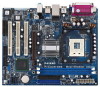
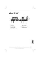
FWH Chip 23 Serial Port Connector (COM1) 24 PCI Slots (PCI1- 3) 25 JR1 / JL1 Jumpers 26 Front Panel Audio Header (AUDIO1) 27 Internal Audio Connector: AUX1 (White) 28 Internal Audio Connector: CD1 (Black) 29 Shared USB 2.0 Header (USB4_5, Blue) 30 North Bridge Controller 2 ASRock P4i65G Motherboard - ASRock P4i65G | Quick Installation Guide - Page 3
ASRock I/O PlusTM 1 Parallel Port 2 RJ-45 Port 3 Line In (Light Blue) 4 Line Out (Lime) 5 Microphone (Pink) 6 Shared USB 2.0 Ports (USB45) 7 USB 2.0 Ports (USB01) 8 USB 2.0 Ports (USB23) 9 VGA Port 10 PS/2 Keyboard Port (Purple) 11 PS/2 Mouse Port (Green) English 3 ASRock P4i65G Motherboard - ASRock P4i65G | Quick Installation Guide - Page 4
modifications of this manual occur, the updated version will be available on ASRock website without further notice. You may find the latest VGA cards and CPU support lists on ASRock website as well. ASRock website http://www.asrock.com 1.1 Package Contents ASRock P4i65G Motherboard (Micro ATX Form - ASRock P4i65G | Quick Installation Guide - Page 5
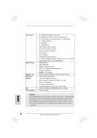
1.2 Specifications Platform CPU Chipset Memory Hybrid Booster Expansion Slot Graphics Audio LAN Rear Panel I/O - Micro ATX Form Factor: 9.6-in x 7.8-in, 24.4 cm x 19.8 cm - Socket 478 for Intel® Pentium® 4 / Celeron® D (Prescott, Northwood, Willamate) processors - FSB 800/533/400 MHz - Supports - ASRock P4i65G | Quick Installation Guide - Page 6
header - CPU/Chassis FAN connector - 20 pin ATX power connector - 4 pin 12V power connector - CD in header - AUX in header - Front panel audio connector - 2 x USB 2.0 headers (support 4 USB 2.0 ports; 2 of them are shared with USB4_5) (see CAUTION 8) - 4Mb AMI BIOS - AMI Legal BIOS - Supports "Plug - ASRock P4i65G | Quick Installation Guide - Page 7
PC system. 7. Do NOT use a 3.3V AGP card on the AGP slot of this motherboard! It may cause permanent damage! 8. Power Management for USB 2.0 works fine under Microsoft® Windows® XP SP1 or SP2 / 2000 SP4. It may not work properly under Microsoft® Windows® 98/ ME. English 7 ASRock P4i65G Motherboard - ASRock P4i65G | Quick Installation Guide - Page 8
you push down the socket lever to secure the CPU. The lever clicks on the side tab to indicate that it is locked. STEP 5: Install CPU fan and heatsink. For proper installation, please kindly refer to the instruction manuals of your CPU fan and heatsink vendors. 8 ASRock P4i65G Motherboard English - ASRock P4i65G | Quick Installation Guide - Page 9
will cause permanent damage to the motherboard and the DIMM if you force the DIMM into the slot at incorrect orientation. Step 3. Firmly insert the DIMM into the slot until the retaining clips at both ends fully snap back in place and the DIMM is properly seated. 9 ASRock P4i65G Motherboard English - ASRock P4i65G | Quick Installation Guide - Page 10
use a 3.3V AGP card on the AGP slot of this motherboard! It may cause permanent damage! AMR slot: AMR slot is used to insert an ASRock MR card (optional) with v.92 Modem functionality. Installing an to the chassis with screws. Step 6. Replace the system cover. 10 ASRock P4i65G Motherboard English - ASRock P4i65G | Quick Installation Guide - Page 11
time, and system setup parameters. To clear and reset the system parameters to default setup, please turn off the computer and unplug the power cord from the power supply. After waiting for 15 seconds, use a jumper cap to short 2 pins on CLRCMOS0 for 5 seconds. English 11 ASRock P4i65G Motherboard - ASRock P4i65G | Quick Installation Guide - Page 12
support SATA data cables for internal storage devices. The current SATA interface allows up to 1.5 Gb/s data transfer rate. Serial ATA (SATA) Data Cable Either end of the SATA data cable can be connected to the SATA hard disk or the SATA connector on the motherboard. English 12 ASRock P4i65G - ASRock P4i65G | Quick Installation Guide - Page 13
from sound sources such as a CD-ROM, DVD-ROM, TV tuner card, or MPEG card. Front Panel AC'97 Audio Header (8-pin AUDIO1) (see p.2 No. 26) This is an interface for the front panel audio cable that allows convenient connection and control of audio devices. English 13 ASRock P4i65G Motherboard - ASRock P4i65G | Quick Installation Guide - Page 14
to any other power, such as USB. 2. HD (Azalia) audio front panel and AC'97 audio front panel have different pin-definition. Incorrect connection of the audio front panel and the front panel audio header may cause permanent damage to this motherboard. System Panel Header (9-pin PANEL1) (see p.2 No - ASRock P4i65G | Quick Installation Guide - Page 15
to the instruction on page 27 of "User Manual" in the support CD. 2.7 Untied Overclocking Technology This motherboard supports Untied Overclocking Technology, which means during overclocking, FSB enjoys better margin due to fixed AGP / PCI bus. You may set "CPU Host Frequency" option of BIOS setup - ASRock P4i65G | Quick Installation Guide - Page 16
about BIOS Setup, please refer to the User Manual (PDF file) contained in the Support CD. 4. Software Support CD information This motherboard supports various Microsoft® Windows® operating systems: 98 SE/ ME / 2000 / XP. The Support CD that came with the motherboard contains necessary drivers and - ASRock P4i65G | Quick Installation Guide - Page 17
17 ASRock P4i65G Motherboard - ASRock P4i65G | Quick Installation Guide - Page 18
® ® ® ® ® ® 18 ASRock P4i65G Motherboard - ASRock P4i65G | Quick Installation Guide - Page 19
® ® 19 ASRock P4i65G Motherboard - ASRock P4i65G | Quick Installation Guide - Page 20
20 ASRock P4i65G Motherboard - ASRock P4i65G | Quick Installation Guide - Page 21
21 ASRock P4i65G Motherboard - ASRock P4i65G | Quick Installation Guide - Page 22
22 ASRock P4i65G Motherboard - ASRock P4i65G | Quick Installation Guide - Page 23
23 ASRock P4i65G Motherboard - ASRock P4i65G | Quick Installation Guide - Page 24
24 ASRock P4i65G Motherboard - ASRock P4i65G | Quick Installation Guide - Page 25
" " SATA2 SATA1 25 ASRock P4i65G Motherboard - ASRock P4i65G | Quick Installation Guide - Page 26
CD1 AUX1 26 ASRock P4i65G Motherboard - ASRock P4i65G | Quick Installation Guide - Page 27
27 ASRock P4i65G Motherboard - ASRock P4i65G | Quick Installation Guide - Page 28
28 ASRock P4i65G Motherboard - ASRock P4i65G | Quick Installation Guide - Page 29
® ® 29 ASRock P4i65G Motherboard - ASRock P4i65G | Quick Installation Guide - Page 30
Kartoninhalt ASRock P4i65G Motherboard (Micro ATX-Formfaktor: 24.4 cm x 19.8 cm; 9.6 Zoll x 7.8 Zoll) ASRock P4i65G Schnellinstallationsanleitung ASRock P4i65G Support-CD Ein 80-adriges Ultra-ATA 66/100 IDE-Flachbandkabel Ein Flachbandkabel für ein 3,5-Zoll-Diskettenlaufwerk Ein Seriell-ATA- (SATA - ASRock P4i65G | Quick Installation Guide - Page 31
Plattform CPU Chipsatz Speicher Hybrid Booster Erweiterungssteckplätze Onboard-VGA Audio LAN E/A-Anschlüsse an der Rückseite - Micro ATX-Formfaktor: 24.4 cm x 19.8 cm; 9.6 Zoll x 7.8 Zoll - Socket 478 für Intel® Pentium® 4 / Celeron® D (Prescott, Northwood, Willamate) Prozessoren - FSB 800/533 - ASRock P4i65G | Quick Installation Guide - Page 32
für CPU-Lüfter - Drehzahlmessung für Gehäuselüfter - Spannungsüberwachung: +12V, +5V, +3.3V, Vcore Betriebssysteme - Unterstützt Microsoft® Windows® 98SE / ME / 2000 / XP Zertifizierungen - FCC, CE, WHQL WARNUNG Beachten Sie bitte, dass Overclocking, einschließlich der Einstellung im BIOS - ASRock P4i65G | Quick Installation Guide - Page 33
dieses Motherboards! Permanente Beschädigung könnte die Folge sein! 8. Das Power Management für USB 2.0 arbeitet unter Microsoft® Windows® XP SP1 oder SP2/2000 SP4 einwandfrei. Unter Microsoft® Windows® 98/ ME könnte es dagegen zu Störungen kommen. Deutsch 33 ASRock P4i65G Motherboard - ASRock P4i65G | Quick Installation Guide - Page 34
. Schritt 5: Installieren Sie einen aktiven CPU-Kühler, der die gesamte Fläche der CPU abdeckt und eine ausreichende Wärmeableitung für den von Ihnen verwendeten CPU-Typ bietet. Weitere Hinweise finden Sie der Installationsanleitung für Ihren CPU-Kühler. 34 ASRock P4i65G Motherboard Deutsch - ASRock P4i65G | Quick Installation Guide - Page 35
2.2 Installation der Speichermodule (DIMM) Das P4i65G Motherboard bietet zwei 184polige DDR (Double Data Rate) DIMMSteckplätze und unterstützt Zweikanal-Speichertechnologie. Es müssen immer Enden des Moduls einschnappen und das DIMM-Modul fest an Ort und Stelle sitzt. 35 ASRock P4i65G Motherboard - ASRock P4i65G | Quick Installation Guide - Page 36
-, und AMR-Slots): Es stehen 3 PCI-, 1 AGP-, und 1 AMR-Slot auf dem P4i65G Motherboard zur Verfügung. PCI-Slots: PCI-Slots werden zur Installation von Erweiterungskarten mit dem 32bit PCI- Schritt 4: Befestigen Sie die Karte mit der Schraube aus Schritt 2. 36 ASRock P4i65G Motherboard Deutsch - ASRock P4i65G | Quick Installation Guide - Page 37
+5VSB (Standby) zu setzen und die PS/2 oder USB- Weckfunktionen zu aktivieren. Hinweis: Um +5VSB nutzen zu kö 25) Hinweis: Sind die Jumper JL1 und JR1 gesetzt funktionieren beide Audioanschlüsse, Front- und Rückseite. CMOS löschen (CLRCMOS0, 2-Pin jumper) (siehe S.2 - ASRock P4i65G Motherboard - ASRock P4i65G | Quick Installation Guide - Page 38
sse (SATA1: siehe S.2 - No. 14) (SATA2: siehe S.2 - No. 13) SATA2 SATA1 Diese beiden Serial ATA(SATA-)Verbínder unterstützten SATA-Datenkabel für interne Massenspeichergeräte. Die aktuelle SATA-Schnittstelle ermöglicht eine Datenübertragungsrate bis 1,5 Gb/s. Deutsch 38 ASRock P4i65G Motherboard - ASRock P4i65G | Quick Installation Guide - Page 39
des vorseitigen USBKabels mit diesem Header (USB4_5) werden die USBAnschlüsse 4,5 auf ASRock I/O Plus™ nicht funktionieren. Anschluss für Infrarot-Modul (5-Pin IR1) (siehe S.2 - No. 19) Dieser Anschluss unterstützt einen optionalen InfrarotSender/Empfänger. Deutsch 39 ASRock P4i65G Motherboard - ASRock P4i65G | Quick Installation Guide - Page 40
das Gehäuselüfterkabel mit diesem Anschluss und passen Sie den schwarzen Draht dem Erdungsstift an. CPU-Lüfteranschluss (3-pin CPU_FAN1) (siehe S.2 - No. 5) Verbinden Sie das CPU Lüfterkabel mit diesem Anschluss und passen Sie den schwarzen Draht dem Erdungsstift an. 40 ASRock P4i65G Motherboard - ASRock P4i65G | Quick Installation Guide - Page 41
kann. Andernfalls reicht der Strom nicht aus, das System zu starten. Dieser COM-AnschlussHeader wird verwendet, um ein COM-Anschlussmodul zu unterstützen. Deutsch 41 ASRock P4i65G Motherboard - ASRock P4i65G | Quick Installation Guide - Page 42
Benutzerhandbuchs auf der Support CD. 2.7 Entkoppelte Übertaktungstechnologie Dieses Motherboard unterstützt die „Untied Overclocking"-Technologie, die durch einen fixierten AGP/PCI-Bus einen besseren FSB-Spielraum beim Übertakten ermöglicht. Im BIOS Setup können Sie die Option „CPU Host-Frequenz - ASRock P4i65G | Quick Installation Guide - Page 43
Delete> oder den Reset-Knopf auf der BIOS-Setup, siehe bitte das Benutzerhandbuch (PDF Datei) auf der Support CD. 4. Software Support CD information Dieses Motherboard unterstützt eine Reiche von Microsoft Windows Betriebssystemen: 98 SE / ME / 2000 / XP. Die Ihrem Motherboard beigefügte Support-CD - ASRock P4i65G | Quick Installation Guide - Page 44
les listes de prise en charge des cartes VGA et CPU également sur le site Web ASRock. Site web ASRock, http://www.asrock.com 1.1 Contenu du paquet Carte mère ASRock P4i65G (Facteur de forme Micro ATX : 9.6 pouces x 7.8 pouces, 24.4 cm x 19.8 cm) Guide d'installation rapide ASRock P4i65G CD de - ASRock P4i65G | Quick Installation Guide - Page 45
Format CPU Chipsets Mémoire L'accélérateur hybride Slot d'extension VGA sur carte Audio LAN Panneau arrière E/S - Facteur de forme Micro ATX: 9.6 pouces x 7.8 pouces, 24.4 cm x 19.8 cm - Socket 478 pour processeurs Intel® Pentium® 4 / Celeron® D (Prescott, Northwood, Willamate) - FSB 800/533 - ASRock P4i65G | Quick Installation Guide - Page 46
de CPU/Châssis - br. 20 connecteur d'alimentation ATX - br. 4 connecteur d'alimentation 12V ATX - Connecteurs audio internes - Connecteur audio panneau avant - 2 x En-tête USB 2.0 (Supporte 4 ports USB 2.0 ; 2 de ces ports sont partagés avec USB4_5) (voir ATTENTION 8) - 4Mb BIOS AMI - BIOS AMI - ASRock P4i65G | Quick Installation Guide - Page 47
de cette carte mère! Cela pourrait l'endommager de manière définitive! 8. La gestion de l'alimentation pour l'USB 2.0 fonctionne bien sous Microsoft® Windows® XP SP1; SP2/2000 SP4. Elle peut ne pas fonctionner correctement sous Microsoft® Windows® 98/ME. Français 47 ASRock P4i65G Motherboard - ASRock P4i65G | Quick Installation Guide - Page 48
bloquer le CPU. Le verrouillage du levier dans son encoche latérale est annoncé par un clic. Etape 5. Installez le ventilateur et le radiateur du CPU. Pour une installation correcte, reportez-vous aux manuels du fabricant du ventilateur et du radiateur de CPU. 48 ASRock P4i65G Motherboard Français - ASRock P4i65G | Quick Installation Guide - Page 49
mémoire non identiques, le système ne sera pas en mesure d'activer la technologie Dual Channel Memory. Installation d'un module DIMM Ayez bien le soin de débrancher l'alimentation avant d'ajouter ou de retirer ètement et que le module DIMM soit inséré correctement. 49 ASRock P4i65G Motherboard - ASRock P4i65G | Quick Installation Guide - Page 50
32 bits. Slot AGP: Le slot AGP est utilisé pour installer une carte graphique. Le slot AGP ASRock utilise un design de fermoir spécial qui permet de fixer correctement la carte graphique insérée. Ne PAS 4. Fixez la carte sur le châssis à l'aide d'une vis. 50 ASRock P4i65G Motherboard Français - ASRock P4i65G | Quick Installation Guide - Page 51
+5VSB (standby) et permettre aux périphériques PS/2 ou USB de réveiller le système. Note: Pour sélectionner +5VSB No. 25) Note: Si les cavaliers JL1 et JR1 sont reliés, les connecteurs audio du panneau avant et du panneau arrière peuvent fonctionner. Effacer la CMOS ( ASRock P4i65G Motherboard - ASRock P4i65G | Quick Installation Guide - Page 52
reporter aux instructions du IDE1, bleu) et votre CD- ROM sur le connecteur SATA) prennent en charge les câbles SATA pour les périphériques de stockage internes. L'interface SATA actuelle permet des taux transferts de données pouvant aller jusqu'à 1,5 Go/s. Français 52 ASRock P4i65G Motherboard - ASRock P4i65G | Quick Installation Guide - Page 53
USB du panneau frontal à cet en-tête (USB4_5), les ports USB 4 et 5 sur ASRock I/O Plus™ ne pourront pas fonctionner. Connecteur module infrarouge (IR1 br. 5) (voir p.2 No. 19) Ce connecteur gère un module en option d'émission/réception sans fil infrarouge. Français 53 ASRock P4i65G Motherboard - ASRock P4i65G | Quick Installation Guide - Page 54
voir p.2 No. 27) CD1 AUX1 Connecteur AC'97 audio u pannea avant (AUDIO1 br. 8) (voir p.2 No. 26) Ils vous permettent de gérer des entrées audio à partir de sources stéréo comme un CD-ROM, DVDROM, un tuner TV ou une carte MPEG fil noir sur la broche de terre. 54 ASRock P4i65G Motherboard Français - ASRock P4i65G | Quick Installation Guide - Page 55
possible de mettre sous tension. Cette en-tête de port COM est utilisée pour prendre en charge un module de port COM. Français 55 ASRock P4i65G Motherboard - ASRock P4i65G | Quick Installation Guide - Page 56
ATA (SATA) Cette carte mère adopte un chipset south bridge Intel ICH5 supportant les disques durs Serial ATA (SATA). Vous pouvez installer des disques durs SATA sur connaître les risques liés à l'overclocking avant d'appliquer la technologie Untied Overclocking. 56 ASRock P4i65G Motherboard Français - ASRock P4i65G | Quick Installation Guide - Page 57
des informations détaillées sur le BIOS, veuillez consulter le Guide de l'utilisateur (fichier PDF) dans le CD technique. 4. Informations sur le CD de support Cette carte mère supporte divers systèmes d'exploitation Microsoft Windows: 98 SE / ME / 2000 / XP. Le CD technique livré avec cette carte - ASRock P4i65G | Quick Installation Guide - Page 58
manuale sia modificato, la versione aggiornata sarà disponibile sul sito di ASRock senza altro avviso. Sul sito ASRock si possono anche trovare le più recenti schede VGA e gli elenchi di CPU supportate. ASRock website http://www.asrock.com 1.1 Contenuto della confezione Scheda madre ASRock P4i65G - ASRock P4i65G | Quick Installation Guide - Page 59
Processore - Socket 478 per Intel® Pentium® 4 / Celeron® D (Prescott, Northwood, Willamate) processore - FSB 800/533/400 MHz - Supporto tecnologia Hyper Threading (vedi ATTENZIONE 1) - Supporta la tecnologia overclocking "slegata" (vedi ATTENZIONE 2) Chipset - Northbridge: Chipset Intel® 865G - ASRock P4i65G | Quick Installation Guide - Page 60
componenti ed alle periferiche del sistema. La procedura è eseguita a proprio rischio ed a proprie spese. Noi non possiamo essere ritenuti responsabili per possibili danni provocati dall'overclocking. Italiano 60 ASRock P4i65G Motherboard - ASRock P4i65G | Quick Installation Guide - Page 61
da 3,3 V nello slot AGP di questa motherboard! Ciò potrebbe provocare danni permanenti! 8. La Gestione Risorse per USB 2.0 funziona perfettamente con Microsoft® Windows® XP SP1; SP2/2000 SP4. Potrebbe dare qualche problema con Microsoft® Windows® 98/ME. Italiano 61 ASRock P4i65G Motherboard - ASRock P4i65G | Quick Installation Guide - Page 62
del processore e l'heatsink. Per una corretta installazione, per favore fare riferimento ai manuali di istruzione dei produttori della ventola e dell'heatsink del processore. Italiano 62 ASRock P4i65G Motherboard - ASRock P4i65G | Quick Installation Guide - Page 63
di memoria, oppure due moduli non identici, non è possibile attivare la tecnologia Dual Channel Memory. Installare una DIMM Scollegare l'alimentazione elettrica prima di aggiungere o rimuovere i DIMM o à e fino ad installare correttamente la DIMM nella sua sede. 63 ASRock P4i65G Motherboard - ASRock P4i65G | Quick Installation Guide - Page 64
sicuro la scheda grafica. NON usare schede AGP da 3,3 V nello slot AGP di questa motherboard! Ciò potrebbe provocare danni permanenti! Per le informazioni relative alla tensione della scheda AGP, si slot. Step 4. Agganciare la scheda allo chassis con le viti. 64 ASRock P4i65G Motherboard Italiano - ASRock P4i65G | Quick Installation Guide - Page 65
settare a +5VSB (standby) e abilitare PS/2 o USB wake up events. Nota: Per selezionare +5VSB, si 25) Nota: Se i jumper JL1 e JR1 sono chiusi, funzionano sia i connettori audio frontali che posteriori. Resettare la CMOS (CLRCMOS0, jumper a 2 pin) (vedi p.2 65 ASRock P4i65G Motherboard - ASRock P4i65G | Quick Installation Guide - Page 66
blu) e il CD-ROM al connettore SATA) supportano cavi dati SATA per dispositivi di immagazzinamento interni. ATA (SATA) supportano cavi SATA per dispositivi di memoria interni. L'interfaccia SATA attuale permette velocità di trasferimento dati fino a 1.5 Gb/s. Italiano 66 ASRock P4i65G Motherboard - ASRock P4i65G | Quick Installation Guide - Page 67
a questo collettore (USB4_5), le porte 4 e 5 su ASRock I/O Plus™ non saranno in grado di funzionare. Connettore modulo infrarossi (5-pin IR1) (vedi p.2 Nr. 19) Questo connettore supporta una wireless opzionale che trasmette e riceve moduli infrarossi. Italiano 67 ASRock P4i65G Motherboard - ASRock P4i65G | Quick Installation Guide - Page 68
del telaio a questo collettore. Collegare il cavo della ventolina telaio a questo connettore e far combaciare il filo nero al pin terra. Collegare il cavo della ventolina CPU a questo connettore e far combaciare il filo nero al pin terra. 68 ASRock P4i65G Motherboard Italiano - ASRock P4i65G | Quick Installation Guide - Page 69
che possa fornire energia sufficiente. In caso contrario l'unità non si avvia. Questo collettore porta COM è utilizzato per supportare il modulo porta COM. Italiano 69 ASRock P4i65G Motherboard - ASRock P4i65G | Quick Installation Guide - Page 70
ma il bus AGP/PCI si trova in modo fisso affinché FSB possa funzionare in un ambiente di overclocking più stabile. Fare riferimento all'avviso di pagina 60 per i possibili rischi dell'overclocking prima di applicare la tecnologia Untied Overclocking Technology. 70 ASRock P4i65G Motherboard Italiano - ASRock P4i65G | Quick Installation Guide - Page 71
del BIOS, fare riferimento al Manuale dell'Utente (PDF file) contenuto nel cd di supporto. 4. Software di supporto e informazioni su CD Questa scheda madre supporta vari sistemi operativi Microsoft® Windows®: 98 SE / ME / 2000 / XP. Il CD di supporto a corredo della scheda madre contiene i driver - ASRock P4i65G | Quick Installation Guide - Page 72
de este manual, la versión actualizada estará disponible en el website de ASRock sin previo aviso. También encontrará las listas de las últimas tarjetas VGA y CPU soportadas en la página web de ASRock. Website de ASRock http://www.asrock.com 1.1 Contenido de la caja Placa base ASRock P4i65G (Factor - ASRock P4i65G | Quick Installation Guide - Page 73
Plataforma Procesador Chipset Memoria Amplificador Híbrido Ranuras de Expansión VGA OnBoard Audio LAN Entrada/Salida de Panel Trasero - Factor forma Micro ATX: 24,4 cm x 19.8 cm, 9,6" x 7,8" - Zócalo 478 para procesador Intel® Pentium® 4 / Celeron® D (Prescott, Northwood, Willamate) - FSB 800/533 - ASRock P4i65G | Quick Installation Guide - Page 74
procesador para proteger el procesador - Taquímetros de los ventiladores del procesador y del chasis - Monitor de Voltaje: +12V, +5V, +3.3V, Vcore - En conformidad con Microsoft® Windows® 98SE / ME / 2000 / XP - FCC, CE, WHQL Español 74 ASRock P4i65G Motherboard - ASRock P4i65G | Quick Installation Guide - Page 75
AGP de 3,3V AGP en la ranura AGP de esta placa base. Podría causar daños permanentes. 8. Power Management para USB 2.0 funciona bien bajo Microsoft® Windows® XP SP1; SP2/2000 SP4. Es posible que no funcione propiamente bajo Microsoft® Windows® 98/ME. Español 75 ASRock P4i65G Motherboard - ASRock P4i65G | Quick Installation Guide - Page 76
del CPU. Si no puede encajar el CPU, examine su orientación o examine si los pins están ya encorvados. Paso 4. Encierre el zócalo bajando la palanca. Paso 5. Instale el disipador de calor con ventilador del CPU (consulte la documentación del disipador de calor). 76 ASRock P4i65G Motherboard Espa - ASRock P4i65G | Quick Installation Guide - Page 77
2.2 Instalación de Memoria La placa base P4i65G proporciona dos ranuras DIMM DDR (Double Data Rate, es decir, Tasa doble de datos) de 184 contactos y sujeción de ambos lados queden completamente introducidos en su sitio y la DIMM se haya asentado apropiadamente. 77 ASRock P4i65G Motherboard Español - ASRock P4i65G | Quick Installation Guide - Page 78
desea utilizar. Paso 3. Encaje el conector de la tarjeta a la slot. Empuje firmemente la tarjeta en la slot. Paso 4. Asegure la tarjeta con tornillos. 78 ASRock P4i65G Motherboard Español - ASRock P4i65G | Quick Installation Guide - Page 79
pin 3 para habilitar +5VSB (standby) para PS/2 o USB wake up events. Atención: Para elegir +5VSB, se necesita corriente puentes JL1 y JR1 son cortos, tanto el conector de audio del panel frontal como del panel posterior pueden funcionar. Limpiar CMOS (CLRCMOS0, jumper de 2 ASRock P4i65G Motherboard - ASRock P4i65G | Quick Installation Guide - Page 80
y el CD-ROM a SATA para dispositivos de almacenamiento internos. La interfaz SATA actual permite una velocidad de transferencia de 1.5 Gb/s. Cable de datos de serie ATA (SATA) Ambos extremos del cable pueden conectarse al disco duro SATA o la conexión de la placa base. 80 ASRock P4i65G Motherboard - ASRock P4i65G | Quick Installation Guide - Page 81
del panel frontal a este cabezal (USB4_5), los puertos USB 4 y 5 en el ASRock I/O PlusTM no funcionarán. Soporta módulo Infrared de transmisión y recepción wireless. Permite recepción de input audio de fuente sónica como CDROM, DVD-ROM TV tuner, o tarjeta MPEG. Español 81 ASRock P4i65G Motherboard - ASRock P4i65G | Quick Installation Guide - Page 82
del chasis a este conector y haga coincidir el cable negro con el conector de tierra. Conecte el cable del ventilador de la CPU a este conector y haga coincidir el cable negro con el conector de tierra. Conecte la fuente de alimentación ATX a su cabezal. Español 82 ASRock P4i65G Motherboard - ASRock P4i65G | Quick Installation Guide - Page 83
configuración de la opción "OnBoard IDE Operate Mode" en la BIOS está correcta según la condición de su sistema. Para obtener detalles sobre la configuración, consulte las instrucciones que aparecen en la página 27 del "Manual del usuario" en el CD de soporte. 83 ASRock P4i65G Motherboard Español - ASRock P4i65G | Quick Installation Guide - Page 84
ón Reset en el panel del ordenador. Para información detallada sobre como configurar la BIOS, por favor refiérase al Manual del Usuario (archivo PDF) contenido en el CD. 4.Información de Software Support CD Esta placa-base soporta diversos tipos de sistema operativo Windows®: 98SE / ME / 2000 / XP
-
 1
1 -
 2
2 -
 3
3 -
 4
4 -
 5
5 -
 6
6 -
 7
7 -
8
-
9
-
10
-
11
-
12
-
13
-
14
-
15
-
16
-
17
-
18
-
19
-
20
-
21
-
22
-
23
-
24
-
25
-
26
-
27
-
28
-
29
-
30
-
31
-
32
-
33
-
34
-
35
-
36
-
37
-
38
-
39
-
40
-
41
-
42
-
43
-
44
-
45
-
46
-
47
-
48
-
49
-
50
-
51
-
52
-
53
-
54
-
55
-
56
-
57
-
58
-
59
-
60
-
61
-
62
-
63
-
64
-
65
-
66
-
67
-
68
-
69
-
70
-
71
-
72
-
73
-
74
-
75
-
76
-
77
-
78
-
79
-
80
-
81
-
82
-
83
-
84
 |
 |

1
ASRock
P4i65G
Motherboard
English
English
English
English
English
Copyright Notice:
Copyright Notice:
Copyright Notice:
Copyright Notice:
Copyright Notice:
No part of this installation guide may be reproduced, transcribed, transmitted, or trans-
lated in any language, in any form or by any means, except duplication of documen-
tation by the purchaser for backup purpose, without written consent of ASRock Inc.
Products and corporate names appearing in this guide may or may not be registered
trademarks or copyrights of their respective companies, and are used only for identifica-
tion or explanation and to the owners’ benefit, without intent to infringe.
Disclaimer:
Disclaimer:
Disclaimer:
Disclaimer:
Disclaimer:
Specifications and information contained in this guide are furnished for informational
use only and subject to change without notice, and should not be constructed as a
commitment by ASRock. ASRock assumes no responsibility for any errors or omissions
that may appear in this guide.
With respect to the contents of this guide, ASRock does not provide warranty of any kind,
either expressed or implied, including but not limited to the implied warranties or
conditions of merchantability or fitness for a particular purpose. In no event shall
ASRock, its directors, officers, employees, or agents be liable for any indirect, special,
incidental, or consequential damages (including damages for loss of profits, loss of
business, loss of data, interruption of business and the like), even if ASRock has been
advised of the possibility of such damages arising from any defect or error in the guide
or product.
This device complies with Part 15 of the FCC Rules. Operation is subject to the
following two conditions:
(1)
this device may not cause harmful interference, and
(2)
this device must accept any interference received, including interference that
may cause undesired operation.
Published November 2006
Copyright
©
2006 ASRock INC. All rights reserved.
CALIFORNIA, USA ONLY
The Lithium battery adopted on this motherboard contains Perchlorate, a toxic
substance controlled in Perchlorate Best Management Practices (BMP) regulations
passed by the California Legislature. When you discard the Lithium battery in
California, USA, please follow the related regulations in advance.
“Perchlorate Material-special handling may apply, see
www
.dtsc.ca.gov/hazardouswa
ste/perchlorate”
ASRock Website: http://www.asrock.com