ASRock P4i65PE User Manual
ASRock P4i65PE Manual
 |
View all ASRock P4i65PE manuals
Add to My Manuals
Save this manual to your list of manuals |
ASRock P4i65PE manual content summary:
- ASRock P4i65PE | User Manual - Page 1
P4i65PE User Manual Version 1.1 Published May 2005 Copyright©2005 ASRock INC. All rights reserved. 1 - ASRock P4i65PE | User Manual - Page 2
any form or by any means, except duplication of documentation by the purchaser for backup purpose, without written consent of ASRock Inc. Products and corporate names appearing in this manual may or may not be registered trademarks or copyrights of their respective companies, and are used only for - ASRock P4i65PE | User Manual - Page 3
and Connectors 16 2.7 Serial ATA (SATA) Hard Disks Installation 19 3 BIOS SETUP UTILITY 20 3.1 Introduction 20 3.1.1 BIOS Menu Bar 20 3.1.2 Navigation Keys 21 3.2 Main Screen 21 3.3 Advanced Screen 21 3.3.1 CPU Configuration 22 3.3.2 Chipset Configuration 23 3.3.3 ACPI Configuration 25 - ASRock P4i65PE | User Manual - Page 4
4 Software Support 35 4.1 Install Operating System 35 4.2 Support CD Information 35 4.2.1 Running Support CD 35 4.2.2 Drivers Menu 35 4.2.3 Utilities Menu 35 4.2.4 ASRock "PC-DIY Live Demo" Program 35 4.2.5 Contact Information 35 4 - ASRock P4i65PE | User Manual - Page 5
any modifications of this manual occur, the updated version will be available on ASRock. website without further notice. You may find the latest memory and CPU support lists on our website as well. ASRock website http://www.asrock.com 1.1 Package Contents ASRock P4i65PE Motherboard (ATX Form Factor - ASRock P4i65PE | User Manual - Page 6
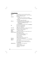
cm CPU: Socket 478, supports Intel® Pentium® 4 / Celeron® (Prescott, Northwood, Willamatte) processor Chipsets: North Bridge: Intel® 865PE chipset, FSB @ 800 / 533 / 400MHz, supports Hyper-Threading Technology (see CAUTION 1) South Bridge: Intel® ICH5, supports SATA 1.5Gb/s Memory: 4 DDR - ASRock P4i65PE | User Manual - Page 7
, it will run at DDR320 if you adopt a DDR333 memory module. 3. This motherboard supports Dual Channel Memory Technology. Before you implement Dual Channel Memory Technology, make sure to read the installation guide of memory modules on page 12 for proper installation. 4. While CPU overheat - ASRock P4i65PE | User Manual - Page 8
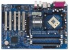
Center: FRONT Bottom: MIC IN ATXPWR1 Intel 865PE Chipset CD1 2Mb BIOS JR1 JL1 1 AUDIO1 AUDIO CODEC GAME1 Super IO AGP 8X 1.5V_AGP1 PCI LAN PCI 1 ` PCI 2 USB2.0 PCI 3 SATA PCI 4 7.1CH FLOPPY1 PCI 5 1 USB45 Intel ICH5 1 USB67 P4i65PE CMOS Battery 1 IR1 1 SPEAKER1 CLRCMOS0 PLED PWRBTN - ASRock P4i65PE | User Manual - Page 9
1.4 ASRock 8CH I/O 1 13 12 11 2 3 6 4 7 5 8 10 9 1 Parallel Port 2 RJ-45 Port 3 table below for connection details in accordance with the type of speaker you use. TABLE for Audio Output Connection Audio Output Channels Front Speaker Rear Speaker Central / Bass (No. 7) (No. 3) (No - ASRock P4i65PE | User Manual - Page 10
Precautions Take note of the following precautions before you install motherboard components or change any motherboard settings. 1. Unplug the power cord from the wall socket before touching any component. 2. To avoid damaging the motherboard components due to static electricity, NEVER place your - ASRock P4i65PE | User Manual - Page 11
Corner to The Socket Marked Corner STEP 4: Push Down And Lock The Socket Lever 2.2 Installation of CPU Fan and Heatsink This motherboard adopts 478-pin CPU socket to support Intel® Pentium®4 For proper installation, please kindly refer to the instruction manuals of the CPU fan and the heatsink. 11 - ASRock P4i65PE | User Manual - Page 12
2.3 Installation of Memory Modules (DIMM) P4i65PE motherboard provides four 184-pin DDR (Double Data Rate) DIMM slots, and supports Dual Channel Memory Technology. For dual channel configuration, you always need to install identical (the same brand, speed, size and chip-type) DDR DIMM pair in the - ASRock P4i65PE | User Manual - Page 13
matches the break on the slot. notch break notch break The DIMM only fits in one correct orientation. It will cause permanent damage to the motherboard and the DIMM if you force the DIMM into the slot at incorrect orientation. Step 3. Firmly insert the DIMM into the slot until the retaining - ASRock P4i65PE | User Manual - Page 14
Slots) There are 5 PCI slots and 1 AGP slot on P4i65PE motherboard. PCI slots: The PCI slots are used to install expansion before you start the installation. Step 2. Remove the system unit cover (if your motherboard is already installed in a chassis). Step 3. Remove the bracket facing the slot that - ASRock P4i65PE | User Manual - Page 15
Note: If the jumpers JL1 and JR1 are short, both the front panel and the rear panel audio connectors can work. Clear CMOS (CLRCMOS0, 2-pin jumper) (see p.8 No. 15) 2-pin need to clear the CMOS when you just finish updating the BIOS, you must boot up the system first, and then shut it down - ASRock P4i65PE | User Manual - Page 16
ATA (SATA) connectors support SATA data cables for internal storage devices. The current SATA interface allows up to 1.5 Gb/s data transfer rate. Serial ATA (SATA) Data Cable Either end of the SATA data cable can be connected to the SATA hard disk or the SATA connector on the motherboard. 16 - ASRock P4i65PE | User Manual - Page 17
support 2 extra USB 2.0 ports. USB 2.0 Header (9-pin USB45) (see p.8, No. 20) USB_PWR P-5 P+5 GND DUMMY 1 GND P+4 P-4 USB_PWR ASRock allow you to receive stereo audio input from sound sources such as a CD-ROM, DVD-ROM, TV tuner card, or MPEG card. Front Panel Audio Header (9-pin AUDIO1) (see - ASRock P4i65PE | User Manual - Page 18
System Panel Header (9-pin PANEL1) (see p.8 No. 16) Chassis Speaker Header (4-pin SPEAKER 1) (see p.8 No. 17) Chassis Fan Connector (3-pin CHA_FAN1) (see p.8 No. 14) CPU Fan Connector (3-pin CPU_FAN1) (see p.8 No. 2) ATX Power Connector (20-pin ATXPWR1) (see p.8 No. 29) PLED+ PLEDPWRBTN# GND 1 - ASRock P4i65PE | User Manual - Page 19
adopts Intel ICH5 south bridge chipset that supports Serial ATA (SATA) hard disks. You may install SATA hard disks on this motherboard for internal storage devices. This section will guide you to install the SATA hard disks. STEP 1: Install the SATA hard disks into the drive bays of your chassis - ASRock P4i65PE | User Manual - Page 20
software is constantly being updated, the following BIOS setup screens and descriptions are for reference purpose only, and they may not exactly match what you see on your screen. 3.1.1 BIOS Menu Bar The top of the screen has a menu bar with the following selections: Main To set up the system - ASRock P4i65PE | User Manual - Page 21
Main Advanced H/W Monitor Boot Security Exit System Overview System Time System Date [14:00:09] [Fri 10/22/2004] BIOS Version : P4i65PE BIOS P1.00 Processor Type : Intel (R) Pentium (R) CPU 3.20 GHz Processor Speed : 3200 MHz Cache Size : 1024KB Microcode Update : 0F34/0E Total Memory - ASRock P4i65PE | User Manual - Page 22
Main BIOS SETUP UTILITY Advanced H/W Monitor Boot Security Exit Advanced Settings WARNING : Setting wrong values in below sections may cause system to malfunction. CPU Configuration Chipset item, which displays whether the ratio status of this motherboard is "Locked" or "Unlocked". If it shows - ASRock P4i65PE | User Manual - Page 23
Limit For Prescott CPU only, some OSes (ex. NT4.0) cannot handle the function with disable. This should be enabled in order to boot legacy OSes that cannot support CPUs with extended CPUID functions. 3.3.2 Chipset Configuration BIOS SETUP UTILITY Advanced Chipset Configuration Bypass Access - ASRock P4i65PE | User Manual - Page 24
selected, the motherboard will detect the memory module(s) inserted memory. It is recommended to leave this field at the default value unless the installed AGP card's specifications requires other sizes. OnBoard LAN This allows you to enable or disable the "OnBoard LAN" feature. OnBoard AC'97 Audio - ASRock P4i65PE | User Manual - Page 25
3.3.3 ACPI Configuration BIOS SETUP UTILITY Advanced ACPI Configuration Suspend To RAM Restore on AC auto-detect or disable the Suspend-toRAM feature. Select [Auto] will enable this feature if the OS supports it. Restore on AC/Power Loss Use this item to set the power state after an unexpected AC/ - ASRock P4i65PE | User Manual - Page 26
3.3.4 IDE Configuration BIOS SETUP UTILITY Advanced IDE SATA + Sec IDE], then the primary IDE will not work. Because Intel® ICH5 south bridge only supports four IDE devices under legacy OS (Windows ME / 98SE), you have to choose either [Pri IDE + SATA] or [SATA + Sec IDE] when the installed SATA - ASRock P4i65PE | User Manual - Page 27
IDE Master" as the example in the following instruction, which can be applied to the configurations of ST340014A :40.0 GB :Supported :16Sectors :4 :MultiWord DMA-2 :Ultra DMA-5 :Supported [Auto] [Auto] drive. After selecting the hard disk information into BIOS, use a disk utility, such as FDISK, to - ASRock P4i65PE | User Manual - Page 28
[Enabled]. 32-Bit Data Transfer Use this item to enable 32-bit access to maximize the IDE hard disk data transfer rate. 3.3.5 PCIPnP Configuration BIOS SETUP UTILITY Advanced PCI / PnP Configuration PCI Latency Timer PCI IDE BusMaster [32] [Enabled] Value in units of PCI clocks for PCI device - ASRock P4i65PE | User Manual - Page 29
Defaults Save and Exit Exit v02.54 (C) Copyright 1985-2003, American Megatrends, Inc. 3.3.7 Super IO Configuration Advanced BIOS SETUP UTILITY Configure Super IO Chipset OnBoard Floppy Controller Serial Port Address Infrared Port Address Parallel Port Address Parallel Port Mode EPP Version ECP - ASRock P4i65PE | User Manual - Page 30
Parallel Port Address Use this item to set the address for the onboard parallel port or disable it. Configuration options: [Disabled], [378], and [278]. Parallel Port Mode Use this item to set the operation mode of the parallel port. The default value is [ECP+EPP]. If this option is set to [ECP+EPP - ASRock P4i65PE | User Manual - Page 31
USB support. 3.4 Hardware Health Event Monitoring Screen In this section, it allows you to monitor the status of the hardware on your system, including the parameters of the CPU temperature, motherboard temperature, CPU fan speed, chassis fan speed, and the critical voltage. Main Advanced BIOS - ASRock P4i65PE | User Manual - Page 32
section, it will display the available devices on your system for you to configure the boot settings and the boot priority. Main Advanced BIOS SETUP UTILITY H/W Monitor Boot Security Exit Boot Settings Boot Settings Configuration 1st Boot Device 2nd Boot Device 3rd Boot Device Hard Disk - ASRock P4i65PE | User Manual - Page 33
set or change the supervisor/user password for the system. For the user password, you may also clear it. BIOS SETUP UTILITY Main Advanced H/W Monitor Boot Security Exit Security Settings Supervisor Password : Not Installed User Password : Not Installed Change Supervisor Password Change - ASRock P4i65PE | User Manual - Page 34
3.7 Exit Screen BIOS SETUP UTILITY Main Advanced H/W Monitro Boot Security Exit Exit Options Save , "Save configuration changes and exit setup?" Select [OK] to save the changes and exit the BIOS SETUP UTILITY. Discard Changes and Exit When you select this option, it will pop-out the following - ASRock P4i65PE | User Manual - Page 35
necessary drivers to activate the devices. 4.2.3 Utilities Menu The Utilities Menu shows the applications software that the motherboard supports. Click on a specific item then follow the installation wizard to install it. 4.2.4 ASRock "PC-DIY Live Demo" Program ASRock presents you a multimedia PC
-
 1
1 -
 2
2 -
 3
3 -
 4
4 -
 5
5 -
 6
6 -
 7
7 -
8
-
9
-
10
-
11
-
12
-
13
-
14
-
15
-
16
-
17
-
18
-
19
-
20
-
21
-
22
-
23
-
24
-
25
-
26
-
27
-
28
-
29
-
30
-
31
-
32
-
33
-
34
-
35
 |
 |

1
P4i65PE
User Manual
Version 1.1
Published May 2005
Copyright©2005 ASRock INC. All rights reserved.