ASRock P4i65PE Quick Installation Guide
ASRock P4i65PE Manual
 |
View all ASRock P4i65PE manuals
Add to My Manuals
Save this manual to your list of manuals |
ASRock P4i65PE manual content summary:
- ASRock P4i65PE | Quick Installation Guide - Page 1
for backup purpose, without written consent of ASRock Inc. Products and corporate names appearing in this guide may or may not be registered trademarks or ASRock Website: http://www.asrock.com Published October 2004 Copyright©2004 ASRock INC. All rights reserved. 1 ASRock P4i65PE Motherboard - ASRock P4i65PE | Quick Installation Guide - Page 2
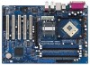
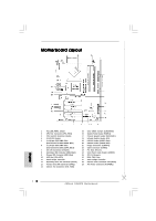
(USB45, Blue) 21 Floppy Connector (FLOPPY1) 22 Game Connector (GAME1) 23 PCI Slots (PCI1- 5) 24 Front Panel Audio Header (AUDIO1) 25 JR1 / JL1 Jumpers 26 BIOS FWH Chip 27 North Bridge Controller 28 Internal Audio Connector: CD1 (Black) 29 ATX Power Connector (ATXPWR1) 2 ASRock P4i65PE Motherboard - ASRock P4i65PE | Quick Installation Guide - Page 3
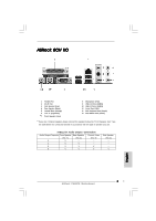
details in accordance with the type of speaker you use. TABLE for Audio Output Connection Audio Output Channels Front Speaker Rear Speaker Central / Bass (No. 7) (No. 4) (No. 5) 2 V -- -- 4 V V -- 6 V V V 8 V V V Side Speaker (No. 3) ---V 3 ASRock P4i65PE Motherboard English - ASRock P4i65PE | Quick Installation Guide - Page 4
modifications of this manual occur, the updated version will be available on ASRock website without further notice. You may find the latest memory and CPU support lists on ASRock website as well. ASRock website http://www.asrock.com 1.1 Package Contents ASRock P4i65PE Motherboard (ATX Form Factor - ASRock P4i65PE | Quick Installation Guide - Page 5
cm CPU: Socket 478, supports Intel® Pentium® 4 / Celeron® (Prescott, Northwood, Willamatte) processor Chipsets: North Bridge: Intel® 865PE chipset, FSB @ 800 / 533 / 400MHz, supports Hyper-Threading Technology (see CAUTION 1) South Bridge: Intel® ICH5, supports SATA 1.5Gb/s Memory: 4 DDR - ASRock P4i65PE | Quick Installation Guide - Page 6
"User Manual" in the Support CD. 2. Please check the table below for the memory support frequency and its corresponding CPU FSB frequency. CPU FSB Frequency Memory Support Frequency 800 DDR266, DDR320*, DDR400 533 DDR266, DDR333 400 DDR266 * When you use an FSB800-CPU on this motherboard - ASRock P4i65PE | Quick Installation Guide - Page 7
while you push down the socket lever to secure the CPU. The lever clicks on the side tab to indicate that it is locked. Install CPU fan and heatsink. For proper installation, please kindly refer to the instruction manuals of your CPU fan and heatsink vendors. English 7 ASRock P4i65PE Motherboard - ASRock P4i65PE | Quick Installation Guide - Page 8
is unable to activate the Dual Channel Memory Technology. 3. If a pair of memory modules is NOT installed in the same Dual Channel, for example, installing a pair of memory modules in DDR1 and DDR2, it is unable to activate the Dual Channel Memory Technology. English 8 ASRock P4i65PE Motherboard - ASRock P4i65PE | Quick Installation Guide - Page 9
Installation of Memory Modules (DIMM) Please make sure to disconnect power supply before adding the slot. The DIMM only fits in one correct orientation. It will cause permanent damage to the motherboard and the DIMM if you force the DIMM into the slot at incorrect orientation. Step 3. Firmly insert - ASRock P4i65PE | Quick Installation Guide - Page 10
: The AGP slot is used to install a graphics card. The ASRock AGP slot has a special locking mechanism which can securely fasten the graphics card inserted. Do NOT use a 3.3V AGP card on the AGP slot of P4i65PE motherboard! It may cause permanent damage! Installing an expansion card Step 1. Before - ASRock P4i65PE | Quick Installation Guide - Page 11
jumpers JL1 and JR1 are short, both the front panel and the rear panel audio connectors can work. Clear CMOS (CLRCMOS0, 2-pin jumper) (see p.2 No. updating the BIOS, you must boot up the system first, and then shut it down before you do the clear-CMOS action. English 11 ASRock P4i65PE Motherboard - ASRock P4i65PE | Quick Installation Guide - Page 12
support SATA data cables for internal storage devices. The current SATA interface allows up to 1.5 Gb/s data transfer rate. Serial ATA (SATA) Data Cable Either end of the SATA data cable can be connected to the SATA hard disk or the SATA connector on the motherboard. 12 ASRock P4i65PE Motherboard - ASRock P4i65PE | Quick Installation Guide - Page 13
audio input from sound sources such as a CD-ROM, DVD-ROM, TV tuner card, or MPEG card. Front Panel Audio Header (9-pin AUDIO1) (see p.2 No. 24) This is an interface for front panel audio cable that allows convenient connection and control of audio devices. English 13 ASRock P4i65PE Motherboard - ASRock P4i65PE | Quick Installation Guide - Page 14
ATX 12V plug to this connector so that it can provides sufficient power. Failing to do so will cause the failure to power up. 14 ASRock P4i65PE Motherboard - ASRock P4i65PE | Quick Installation Guide - Page 15
need to check and ensure the configuration of the OnBoard IDE Operate Mode option in BIOS setup is correct according to the condition of your system. For the configuration details, please refer to the instruction on page 26 of "User Manual" in the Support CD. 15 ASRock P4i65PE Motherboard English - ASRock P4i65PE | Quick Installation Guide - Page 16
the BIOS Setup Utility, please refer to the User Manual (PDF file) contained in the Support CD. 4. Software Support CD information This motherboard supports various Microsoft® Windows® operating systems: 98 SE/ ME / 2000 / XP. The Support CD that came with the motherboard contains necessary drivers - ASRock P4i65PE | Quick Installation Guide - Page 17
17 ASRock P4i65PE Motherboard - ASRock P4i65PE | Quick Installation Guide - Page 18
® ® Intel® ICH5, ® ® 18 ASRock P4i65PE Motherboard - ASRock P4i65PE | Quick Installation Guide - Page 19
® ® 19 ASRock P4i65PE Motherboard - ASRock P4i65PE | Quick Installation Guide - Page 20
20 ASRock P4i65PE Motherboard - ASRock P4i65PE | Quick Installation Guide - Page 21
21 ASRock P4i65PE Motherboard - ASRock P4i65PE | Quick Installation Guide - Page 22
22 ASRock P4i65PE Motherboard - ASRock P4i65PE | Quick Installation Guide - Page 23
23 ASRock P4i65PE Motherboard - ASRock P4i65PE | Quick Installation Guide - Page 24
" " SATA2 SATA1 24 ASRock P4i65PE Motherboard - ASRock P4i65PE | Quick Installation Guide - Page 25
CD1 25 ASRock P4i65PE Motherboard - ASRock P4i65PE | Quick Installation Guide - Page 26
26 ASRock P4i65PE Motherboard - ASRock P4i65PE | Quick Installation Guide - Page 27
27 ASRock P4i65PE Motherboard - ASRock P4i65PE | Quick Installation Guide - Page 28
"PC-DIY Live Demo" " ® ® " 28 ASRock P4i65PE Motherboard - ASRock P4i65PE | Quick Installation Guide - Page 29
Kartoninhalt ASRock P4i65PE Motherboard (ATX-Formfaktor: 30.5 cm x 20.8 cm; 12.0 Zoll x 8.2 Zoll) ASRock P4i65PE Schnellinstallationsanleitung ASRock P4i65PE_ Support-CD Ein 80-adriges Ultra-ATA 66/100 IDE-Flachbandkabel Ein Flachbandkabel für ein 3,5-Zoll-Diskettenlaufwerk Ein Seriell-ATA- (SATA - ASRock P4i65PE | Quick Installation Guide - Page 30
x 8.2 Zoll CPU: Socket 478 für Intel® Pentium® 4 / Celeron® (Prescott, Northwood, Willamatte) Prozessoren Chipsatz: North Bridge: Intel® 865PE-Chipsatz, FSB @ 800/533/400 MHz, unterstützt Hyper-Threading Technology (siehe VORSICHT 1) South Bridge: Intel® ICH5, unterstützt SATA 1.5Gb/s RAM - ASRock P4i65PE | Quick Installation Guide - Page 31
BIOS: AMI legal BIOS der Support-CD Motherboards unterstützt Stereo- und Mono- Modi. Der Audioausgang dieses Motherboards unterstützt 2-Kanal-, 4-Kanal-, 6-Kanal- und 8-Kanal-Modi. Stellen Sie die richtige Verbindung anhand der Tabelle auf Seite 3 her. Deutsch 31 ASRock P4i65PE Motherboard - ASRock P4i65PE | Quick Installation Guide - Page 32
der Montage Bitte nehmen Sie die folgende Sicherheitshinweise zur Kenntnis, bevor Sie das Motherboard einbauen oder Veränderungen an den Einstellungen vornehmen. 1. Trennen Sie das . Weitere Hinweise finden Sie der Installationsanleitung für Ihren CPU-Kühler. 32 ASRock P4i65PE Motherboard Deutsch - ASRock P4i65PE | Quick Installation Guide - Page 33
2.2 Installation der Speichermodule (DIMM) Die Motherboards P4i65PE bieten vier 184-pol. DDR (Double Data Rate) DIMMSteckplätze und unterstützen die Dual-Kanal- wird in DDR1 und DDR2 installiert, kann es die Dual-Kanal-Speichertechnologie nicht aktivieren. Deutsch 33 ASRock P4i65PE Motherboard - ASRock P4i65PE | Quick Installation Guide - Page 34
in die Steckplätze, so dass die Halteklammern an beiden Enden des Moduls einschnappen und das DIMM-Modul fest an Ort und Stelle sitzt. 34 ASRock P4i65PE Motherboard - ASRock P4i65PE | Quick Installation Guide - Page 35
5 PCI- und 1 AGP-Slot auf dem P4i65PE Motherboard zur Verfügung. PCI-Slots: PCI-Slots werden zur Installation von Erweiterungskarten mit dem 32bit PCI-Interface genutzt. AGP-Slot: Der AGP-Steckplatz dient zur Installation einer Grafikkarte. Der ASRock AGP-Steckplatz hat speziell entwickelte Klammern - ASRock P4i65PE | Quick Installation Guide - Page 36
Sie nicht, den Jumper wieder zu entfernen, nachdem das CMOS gelöscht wurde. Wenn Sie den CMOS- Inhalt gleich nach dem Aktualisieren des BIOS löschen müssen, müssen Sie zuerst das System starten und dann wieder ausschalten, bevor Sie den CMOS-Inhalt löschen. Deutsch 36 ASRock P4i65PE Motherboard - ASRock P4i65PE | Quick Installation Guide - Page 37
wird das Motherboard unreparierbar beschä SATA-Schnittstelle ermöglicht eine Datenübertragungsrate bis 1,5 Gb/s. Serial ATA- (SATA-) Datenkabel Sie können beide Enden des SATA-Datenkabels entweder mit der SATA-Festplatte oder dem SATA-Anschluss am Mainboard verbinden. 37 ASRock P4i65PE Motherboard - ASRock P4i65PE | Quick Installation Guide - Page 38
ein optionales, drahtloses Sendeund Empfangs-Infrarotmodul. Interne Audio-Anschlüsse (4-Pin CD1) (CD1: siehe S.2 - No. 28) CD1 Diese ermöglichen Ihnen Stereo-Signalquellen, wie z. B. CD-ROM, DVD-ROM, TV-Tuner oder MPEG-Karten mit Ihrem System zu verbinden. Deutsch 38 ASRock P4i65PE Motherboard - ASRock P4i65PE | Quick Installation Guide - Page 39
- No. 29) Game Port-Anschluss (15-pin GAME1) (siehe S.2 - No. 22) Dieses Interface zu einem Audio-Panel auf der Vorderseite Ihres Gehäuses, ermöglicht Ihnen eine bequeme Anschlussmöglichkeit und Kontrolle über , wenn der Game Port-Halter installiert ist. Deutsch 39 ASRock P4i65PE Motherboard - ASRock P4i65PE | Quick Installation Guide - Page 40
auf der SATA-Festplatte müssen Sie sicherstellen, dass die Konfiguration der Option "OnBoard IDE Operate Mode" im BIOS-Setup entsprechend den Bedingungen Ihres Systems richtig ist. Konfigurationsdetails finden Sie auf Seite 26 des Benutzerhandbuchs auf der Support CD. 40 ASRock P4i65PE Motherboard - ASRock P4i65PE | Quick Installation Guide - Page 41
durch Drücken der Reset-Tasten am Systemgehäuse. Details über das BIOS-Setup-Programm entnehmen Sie bitte der Bedienungsanleitung (PDF-Datei) auf der Support-CD. 4. Software Support CD information Dieses Motherboard unterstützt eine Reiche von Microsoft Windows Betriebssystemen: 98 SE / ME / 2000 - ASRock P4i65PE | Quick Installation Guide - Page 42
ASRock P4i65PE CD de soutien ASRock P4i65PE Un câble ruban IDE Ultra ATA 66/100 80 conducteurs Un câble ruban pour un lecteur de disquettes 3,5 pouces Un câble de données Serial ATA (SATA) Un cordon d'alimentation DD série ATA (SATA) (en option) Un écran ASRock 8CH I/O 42 ASRock P4i65PE Motherboard - ASRock P4i65PE | Quick Installation Guide - Page 43
20.8 cm CPU: Socket 478 pour processeurs Intel® Pentium® 4 (Prescott, Northwood, Willamatte) / Celeron® Chipsets: North Bridge: Chipset Intel® 865PE, FSB de 800/533/400 MHz, supporte la Technologie Hyper-Threading (voir ATTENTION 1) South Bridge: Intel® ICH5, supporte SATA 1.5Go/s Mémoire - ASRock P4i65PE | Quick Installation Guide - Page 44
quence de prise en charge mémoire 800 DDR266, DDR320*, DDR400 533 DDR266, assurez- vous de bien lire le guide d'installation des modules mémoire en supporte les deux modes stéréo et mono. Pour la sortie audio, cette carte mère supporte les modes 2- Français 44 ASRock P4i65PE Motherboard - ASRock P4i65PE | Quick Installation Guide - Page 45
support pour bloquer le CPU. Le verrouillage du levier dans son encoche latérale est annoncé par un clic. Etape 5. Installez le ventilateur et le radiateur du CPU. Pour une installation correcte, reportez-vous aux manuels du fabricant du ventilateur et du radiateur de 45 ASRock P4i65PE Motherboard - ASRock P4i65PE | Quick Installation Guide - Page 46
des modules m émoire [DIMM] La carte mère P4i65PE dispose de quatre emplacements DIMM DDR (Double Data Rate) de 184-broches, et supporte la Technologie de Mémoire à Canal Double. Pour effectuer impossible d'activer la Technologie de Mémoire à Canal Double. Français 46 ASRock P4i65PE Motherboard - ASRock P4i65PE | Quick Installation Guide - Page 47
jusqu'à ce que les clips de maintien situés aux deux extrémités se ferment complètement et que le module DIMM soit inséré correctement. 47 ASRock P4i65PE Motherboard - ASRock P4i65PE | Quick Installation Guide - Page 48
32 bits. Slot AGP: Le slot AGP est utilisé pour installer une carte graphique. Le slot AGP ASRock utilise un design de fermoir spécial qui permet de fixer correctement la carte graphique insérée. Ne PAS 4. Fixez la carte sur le châssis à l'aide d'une vis. 48 ASRock P4i65PE Motherboard Français - ASRock P4i65PE | Quick Installation Guide - Page 49
. 25) Note: Si les cavaliers JL1 et JR1 sont reliés, les connecteurs audio du panneau avant et du panneau arrière peuvent fonctionner. Effacer la CMOS ( BIOS, vous devrez d'abord démarrer le système puis l'arrêter avant d'effectuer l'effacement de la CMOS. Français 49 ASRock P4i65PE Motherboard - ASRock P4i65PE | Quick Installation Guide - Page 50
Maître". Veuillez vous reporter aux instructions du fabricant de votre IDE pé SATA) prennent en charge les câbles SATA pour les périphériques de stockage internes. L'interface SATA actuelle permet des taux transferts de données pouvant aller jusqu'à 1,5 Go/s. Français 50 ASRock P4i65PE Motherboard - ASRock P4i65PE | Quick Installation Guide - Page 51
2.0-Header (USB_H45) zur Unterstützung 2 weiterer USB 2.0-Anschlüsse zur Verfügung. En-tête du module infrarouge (5-pin IR1) (voir p.2 No. 18) Cet en-tête supporte un module infrarouge optionnel de transfert et de réception sans fil. Français 51 ASRock P4i65PE Motherboard - ASRock P4i65PE | Quick Installation Guide - Page 52
carte MPEG. C'est une interface pour un câble audio en façade qui permet le branchement et le contrôle commodes de périphériques audio. Cet en-tête permet d'utiliser plusieurs fonctions du câble Port Jeux à ce connecteur si le support Port Jeux est installé. Français 52 ASRock P4i65PE Motherboard - ASRock P4i65PE | Quick Installation Guide - Page 53
de l'option"OnBoard IDE Operate Mode" dans la configuration du BIOS en fonction de l'état de votre système. Pour les détails de la configuration, veuillez vous reporter aux instructions à la page 26 du "Manuel de l'utilisateur" sur le CD d'assistance. Français 53 ASRock P4i65PE Motherboard - ASRock P4i65PE | Quick Installation Guide - Page 54
multimédia, qui vous présente un guide pas à pas pour l'installation de votre propre système PC. Pour voir cette démo, vous pouvez exécuter "Microsoft Lecteur multimédia" pour lire le fichier. Le fichier se trouve sur le chemin suivant : ..\ MPEG \ AVSEQ01.DAT 54 ASRock P4i65PE Motherboard Français - ASRock P4i65PE | Quick Installation Guide - Page 55
cm) Guida di installazione rapida ASRock P4i65PE CD di supporto ASRock P4i65PE Un cavo IDE 80-pin Ultra ATA 66/100 Un cavo per floppy drive a 1,44 Mb Un cavo dati Serial ATA (SATA) Un cavo alimentatore HDD Serial ATA (SATA) (Opzionale) Un ASRock 8CH I/O Shield 55 ASRock P4i65PE Motherboard Italiano - ASRock P4i65PE | Quick Installation Guide - Page 56
x 20.8 cm Processore: Socket 478 per Intel® Pentium® 4(Prescott, Northwood, Willamatte)/ Celeron® processore Chipset: North Bridge: Chipset Intel® 865PE, FSB @ 800/533/400 MHz, Supporto tecnologia Hyper-Threading (vedi ATTENZIONE 1) South Bridge: Intel® ICH5, supporta SATA 1.5Gb/s Memoria - ASRock P4i65PE | Quick Installation Guide - Page 57
les deux modes stéréo et mono. Pour la sortie audio, cette carte mère supporte les modes 2- canaux, 4-canaux, 6-canaux et 8-canaux. Veuillez vous référer au tableau en page 3 pour effectuer la bonne connexion. 8. Anche se questa motherboard offre il controllo stepless, non si consiglia di - ASRock P4i65PE | Quick Installation Guide - Page 58
ventola del processore e l'heatsink. Per una corretta installazione, per favore fare riferimento ai manuali di istruzione dei produttori della ventola e dell'heatsink del processore. 58 ASRock P4i65PE Motherboard Italiano - ASRock P4i65PE | Quick Installation Guide - Page 59
attivare la tecnologia Dual Channel Memory. 3. Se una coppia di moduli di memoria NON è installata nello stesso "canale doppio", ad esempio se si installa una coppia di moduli di memoria su DDR1 e DD2, è impossibile attivare la tecnologia Dual Channel Memory. Italiano 59 ASRock P4i65PE Motherboard - ASRock P4i65PE | Quick Installation Guide - Page 60
DIMM nello slot fino a far scattare completamente in posizione i fermagli di ritegno alle due estremità e fino ad installare correttamente la DIMM nella sua sede. 60 ASRock P4i65PE Motherboard - ASRock P4i65PE | Quick Installation Guide - Page 61
della scheda con lo slot e premere con decisione finché la scheda è completamente inserita nello slot. Step 4. Agganciare la scheda allo chassis con le viti. 61 ASRock P4i65PE Motherboard Italiano - ASRock P4i65PE | Quick Installation Guide - Page 62
Se i jumper JL1 e JR1 sono chiusi, funzionano sia i connettori audio frontali che posteriori. Resettare la CMOS (CLRCMOS0, jumper a 2 BIOS, prima di eseguire tale operazione di cancellazione è necessario riavviare innanzitutto il sistema, e quindi spegnerlo. Italiano 62 ASRock P4i65PE Motherboard - ASRock P4i65PE | Quick Installation Guide - Page 63
due connettori Serial ATA (SATA) supportano cavi dati SATA per dispositivi di immagazzinamento interni. ATA (SATA) supportano cavi SATA per dispositivi di memoria interni. L'interfaccia SATA attuale permette velocità di trasferimento dati fino a 1.5 Gb/s. Italiano 63 ASRock P4i65PE Motherboard - ASRock P4i65PE | Quick Installation Guide - Page 64
supporta moduli ad infrarossi optional per la trasmissione e la ricezione senza fili. Connettori audio interni Permettono di ricevere input (4-pin CD1) stereo audio da fonti di (CD1: vedi p.2 Nr. 28) suono come CD-ROM, DVD - CD1 ROM,TV tuner, o schede MPEG. 64 ASRock P4i65PE Motherboard - ASRock P4i65PE | Quick Installation Guide - Page 65
Nr. 22) È un'interfaccia per il cavo del pannello audio. Che consente connessione facile e controllo dei dispositivi audio. Questo collettore accomoda diverse funzioni di sistema pannello frontale. collettore se la staffa per la porta giochi è installata. Italiano 65 ASRock P4i65PE Motherboard - ASRock P4i65PE | Quick Installation Guide - Page 66
ATA Seriali (SATA) Questa scheda madre adotta il Chipset South bridge ICH5 che supporta dischi rigidi Serial ATA (SATA). Potete installare hard disk SATA su questa riferimento alle istruzioni di pagina 26 del "Manuale dell'utente" contenuto nel CD di supporto. Italiano 66 ASRock P4i65PE Motherboard - ASRock P4i65PE | Quick Installation Guide - Page 67
del sistema. Fare riferimento al Manuale dell'utente (file PDF), contenuto nel CD di supporto, per informazioni dettagliate sull'utilità di configurazione del BIOS. 4. Software di supporto e eseguire il file. Il percorso del file è: ..\ MPEGAV \ AVSEQ01.DAT 67 ASRock P4i65PE Motherboard Italiano - ASRock P4i65PE | Quick Installation Guide - Page 68
de ASRock P4i65PE Una cinta de datos IDE de conducción 80 Ultra ATA 66/100 Una cinta de datos para una unidad de disco de 3,5" Un Cable de Datos Serial ATA (SATA) Un cable serie ATA (SATA) de alimentación de disco duro (Opcional) Una protección ASRock 8CH I/O 68 ASRock P4i65PE Motherboard Espa - ASRock P4i65PE | Quick Installation Guide - Page 69
: Factor forma ATX: 30,5 cm x 20,8 cm, 12,0" x 8,2" Procesador: Zócalo 478 para procesador Intel® Pentium® 4 (Prescott, Northwood, Willamatte) / Celeron® Chipset: North Bridge: Intel® 865PE chipset, FSB @ 800/533/400 MHz, soporta la tecnología Hyper-Threading (vea ATENCIÓN 1) South bridge - ASRock P4i65PE | Quick Installation Guide - Page 70
audio: Altavoz lateral / Altavoz trasero / Central/Bajos / Entrada de línea / Altavoz frontal / Micrófono (ver ATENCIÓN 7) AMI legal BIOS, Soporta "Plug and Play", ACPI 1.1 compliance wake up events, Soporta "jumper free en el sistema o dañar la CPU. 70 ASRock P4i65PE Motherboard Español - ASRock P4i65PE | Quick Installation Guide - Page 71
. Paso 4. Encierre el zócalo bajando la palanca. Paso 5. Instale el disipador de calor con ventilador del CPU ( consulte la documentación del disipador de calor). 71 ASRock P4i65PE Motherboard Español - ASRock P4i65PE | Quick Installation Guide - Page 72
2.2 Instalación de Memoria La placa P4i65PE ofrece cuatro ranuras DIMM DDR de 184 pines, y soporta Tecnología de Memoria de Doble Canal. Para la configuración de dulos de memoria en DDR1 y DDR2, no será posible activar la Tecnología de Memoria de Doble Canal. Español 72 ASRock P4i65PE Motherboard - ASRock P4i65PE | Quick Installation Guide - Page 73
de la ranura hasta que los clips de sujeción de ambos lados queden completamente introducidos en su sitio y la DIMM se haya asentado apropiadamente. 73 ASRock P4i65PE Motherboard Español - ASRock P4i65PE | Quick Installation Guide - Page 74
desea utilizar. Paso 3. Encaje el conector de la tarjeta a la slot. Empuje firmemente la tarjeta en la slot. Paso 4. Asegure la tarjeta con tornillos. 74 ASRock P4i65PE Motherboard Español - ASRock P4i65PE | Quick Installation Guide - Page 75
Si los puentes JL1 y JR1 son cortos, tanto el conector de audio del panel frontal como del panel posterior pueden funcionar. Limpiar CMOS ( BIOS, debe arrancar primero el sistema y, a continuación, apagarlo antes de realizar la acción de borrado de CMOS. Español 75 ASRock P4i65PE Motherboard - ASRock P4i65PE | Quick Installation Guide - Page 76
cables SATA para dispositivos de almacenamiento internos. La interfaz SATA actual permite una velocidad de transferencia de 1.5 Gb/s. Cable de datos de serie ATA (SATA) Ambos extremos del cable pueden conectarse al disco duro SATA o la conexión de la placa base. 76 ASRock P4i65PE Motherboard - ASRock P4i65PE | Quick Installation Guide - Page 77
18) Este cabezal soporta un módulo infrarrojos de transmisión y recepción wireless opcional. Conector de audio interno (4-pin CD1) (CD1: vea p. 2, N. 28) CD1 Permite recepción de input audio de fuente sónica como CDROM, DVD-ROM, TV tuner, o tarjeta MPEG. Español 77 ASRock P4i65PE Motherboard - ASRock P4i65PE | Quick Installation Guide - Page 78
vea p.2, N. 22) Este es una interface para cable de audio de panel frontal que permite conexión y control conveniente de apparatos de Audio. Este cabezar acomoda varias dunciones de panel frontal de sistema. Conecte si el Puerto de Juegos está instalado. Español 78 ASRock P4i65PE Motherboard - ASRock P4i65PE | Quick Installation Guide - Page 79
configuración de la opción "OnBoard IDE Operate Mode" en la BIOS está correcta según la condición de su sistema. Para obtener detalles sobre la configuración, consulte las instrucciones que aparecen en la página 26 del "Manual del usuario" en el CD de soporte. Español 79 ASRock P4i65PE Motherboard - ASRock P4i65PE | Quick Installation Guide - Page 80
BIOS, consulte el Manual del usuario (archivo PDF), que se encuentra en el CD de soporte. 4.Información de Software Support para iniciar la instalación. "PC-DIY Live Demo" ASRock presenta una demostración en vivo multimedia PC-DIY, que le muestra una guía paso 80 ASRock P4i65PE Motherboard Español
-
 1
1 -
 2
2 -
 3
3 -
 4
4 -
 5
5 -
 6
6 -
 7
7 -
8
-
9
-
10
-
11
-
12
-
13
-
14
-
15
-
16
-
17
-
18
-
19
-
20
-
21
-
22
-
23
-
24
-
25
-
26
-
27
-
28
-
29
-
30
-
31
-
32
-
33
-
34
-
35
-
36
-
37
-
38
-
39
-
40
-
41
-
42
-
43
-
44
-
45
-
46
-
47
-
48
-
49
-
50
-
51
-
52
-
53
-
54
-
55
-
56
-
57
-
58
-
59
-
60
-
61
-
62
-
63
-
64
-
65
-
66
-
67
-
68
-
69
-
70
-
71
-
72
-
73
-
74
-
75
-
76
-
77
-
78
-
79
-
80
 |
 |
1
ASRock
P4i65PE
Motherboard
English
English
English
English
English
Copyright Notice:
Copyright Notice:
Copyright Notice:
Copyright Notice:
Copyright Notice:
No part of this installation guide may be reproduced, transcribed, transmitted, or
translated in any language, in any form or by any means, except duplication of
documentation by the purchaser for backup purpose, without written consent of
ASRock Inc.
Products and corporate names appearing in this guide may or may not be registered
trademarks or copyrights of their respective companies, and are used only for
identification or explanation and to the owners’ benefit, without intent to infringe.
Disclaimer:
Disclaimer:
Disclaimer:
Disclaimer:
Disclaimer:
Specifications and information contained in this guide are furnished for informational
use only and subject to change without notice, and should not be constructed as a
commitment by ASRock. ASRock assumes no responsibility for any errors or
omissions that may appear in this guide.
With respect to the contents of this guide, ASRock does not provide warranty of any
kind, either expressed or implied, including but not limited to the implied warranties or
conditions of merchantability or fitness for a particular purpose.
In no event shall ASRock, its directors, officers, employees, or agents be liable for
any indirect, special, incidental, or consequential damages (including damages for
loss of profits, loss of business, loss of data, interruption of business and the like),
even if ASRock has been advised of the possibility of such damages arising from any
defect or error in the guide or product.
This device complies with Part 15 of the FCC Rules. Operation is subject to the
following two conditions:
(1)
this device may not cause harmful interference, and
(2)
this device must accept any interference received, including interference that
may cause undesired operation.
ASRock Website: http://www.asrock.com
Published October 2004
Copyright
©
2004 ASRock INC. All rights reserved.