ASRock P55 Deluxe User Manual
ASRock P55 Deluxe Manual
 |
View all ASRock P55 Deluxe manuals
Add to My Manuals
Save this manual to your list of manuals |
ASRock P55 Deluxe manual content summary:
- ASRock P55 Deluxe | User Manual - Page 1
P55 Deluxe User Manual Version 1.1 Published August 2009 Copyright©2009 ASRock INC. All rights reserved. 1 - ASRock P55 Deluxe | User Manual - Page 2
commitment by ASRock. ASRock assumes no responsibility for any errors or omissions that may appear in this manual. With respect to the contents of this manual, ASRock does not , USA ONLY The Lithium battery adopted on this motherboard contains Perchlorate, a toxic substance controlled in Perchlorate - ASRock P55 Deluxe | User Manual - Page 3
2.17 Hot Plug and Hot Swap Functions for SATA / SATAII HDDs 44 2.18 SATA / SATAII HDD Hot Plug Feature and Operation Guide 45 2.19 Driver Installation Guide 47 2.20 Installing Windows® XP / XP 64-bit / VistaTM / VistaTM 64-bit With RAID Functions 47 2.20.1 Installing Windows® XP / XP 64-bit With - ASRock P55 Deluxe | User Manual - Page 4
VistaTM 64-bit Without RAID Functions 51 2.21.1 Installing Windows® XP / XP 64-bit Without RAID Functions 51 2.21.2 Installing Windows® VistaTM / VistaTM 64-bit Without RAID Functions 52 2.22 DTS Operation Guide 53 2.23 Untied Overclocking Technology 55 3 BIOS SETUP UTILITY 56 3.1 Introduction - ASRock P55 Deluxe | User Manual - Page 5
Package Contents ASRock P55 Deluxe Motherboard (ATX Form Factor: 12.0-in x 9.6-in, 30.5 cm x 24.4 cm) ASRock P55 Deluxe Quick Installation Guide ASRock P55 Deluxe Support CD 1 x 80-conductor Ultra ATA 66/100/133 IDE Ribbon Cable 1 x Ribbon Cable for a 3.5-in Floppy Drive 4 x Serial ATA (SATA) Data - ASRock P55 Deluxe | User Manual - Page 6
NVIDIA® SLITM and Quad SLITM - 7.1 CH Windows® VistaTM Premium Level HD Audio with Content Protection - DAC with 110dB dynamic range (ALC890 Audio Codec) - DTS (Digital Theater Systems) support (see CAUTION 6) - Premium Blu-ray audio support - PCIE x1 Gigabit LAN 10/100/1000 Mb/s - Realtek RTL8111DL - ASRock P55 Deluxe | User Manual - Page 7
" - ACPI 1.1 Compliance Wake Up Events - Supports jumperfree - SMBIOS 2.3.1 Support - CPU, VCCM, SB, VTT Voltage Multi-adjustment - Supports I. O. T. (Intelligent Overclocking Technology) - Supports Smart BIOS - Drivers, Utilities, AntiVirus Software (Trial Version) - ASRock OC Tuner (see CAUTION 10 - ASRock P55 Deluxe | User Manual - Page 8
This motherboard supports Untied Overclocking Technology. Please read "Untied Overclocking Technology" on page 55 for details. 3. This motherboard supports Dual Channel Memory Technology. Before you implement Dual Channel Memory Technology, make sure to read the installation guide of memory modules - ASRock P55 Deluxe | User Manual - Page 9
digital surround sound format. To enable DTS function, you need to adjust the settings after audio driver installation. Please refer to "DTS Operation Guide" on page 53 for details. 7. For microphone input, this motherboard supports both stereo and mono modes. For audio output, this motherboard - ASRock P55 Deluxe | User Manual - Page 10
LGA 775 and LGA 1156. an EuP ready motherboard and an EuP ready Name Driver GeForce supported under Windows® XP / XP 64-bit only. * For the latest updates of the supported PCI Express VGA card list for SLITM Mode, please visit our website for details. ASRock website: http://www.asrock.com/support - ASRock P55 Deluxe | User Manual - Page 11
.asrock.com/support/index.htm 1.5 Three CrossFireXTM Graphics Card Support List (for Windows® VistaTM / VistaTM 64-bit) Chipset Vendor ATI Model Name Powercolor AX4670 512MD3-P Gecube GC-HD485PG3-E3 Chipset Name RADEON 4670 RADEON 4850 Driver Catalyst 9.6 Catalyst 9.6 * For the latest updates - ASRock P55 Deluxe | User Manual - Page 12
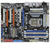
Motherboard P55 Deluxe PCIE1 CHA_FAN3 LAN PHY Dual GLAN PCI1 PCIE2 EuP Ready CMOS Battery CrossFireX 1394a Super I/O PCIE3 PCI Express 2.0 16Mb BIOS Intel P55 IDE1 SATAII_5_6 SATAII_3_4 SATAII_1_2 PCI2 RoHS AUDIO USB8_9, Blue) 3 1156-Pin CPU Socket 24 Intel P55 Chipset 4 Chassis - ASRock P55 Deluxe | User Manual - Page 13
below for connection details in accordance with the type of speaker you use. TABLE for Audio Output Connection Audio Output Channels Front Speaker Rear Speaker Central / Bass Side Speaker (No. 11) (No. 8) (No. 9) (No. 7) 2 V -- -- -- 4 V -- -- V 6 V -- V V 8 V V V V To - ASRock P55 Deluxe | User Manual - Page 14
settings. 1. Unplug the power cord from the wall socket before touching any component. 2. To avoid damaging the motherboard components due to static electricity, NEVER place your motherboard directly on the carpet or the like. Also remember to use a grounded wrist strap or touch a safety grounded - ASRock P55 Deluxe | User Manual - Page 15
please follow the steps below. Load Plate Load Lever Contact Array Socket Body 1156-Pin Socket Overview Before you insert the 1156-Pin CPU into the socket, please check if the CPU surface is unclean off the PnP cap. 2. This cap must be placed if returning the motherboard for after service. 15 - ASRock P55 Deluxe | User Manual - Page 16
Heat Sink) up. Locate Pin1 and the two orientation key notches. orientation key notch alignment key Pin1 Pin1 orientation key notch 1156-Pin CPU alignment key 1156-Pin Socket For proper inserting, please ensure to match the two orientation key notches of the CPU with the two alignment keys - ASRock P55 Deluxe | User Manual - Page 17
with fan operation or contact other components. Please be noticed that this motherboard supports Combo Cooler Option (C.C.O.), which provides the flexible option to adopt two different CPU cooler types, Socket LGA 775 and LGA 1156. The white throughholes are for Socket LGA 1156 CPU fan. 17 - ASRock P55 Deluxe | User Manual - Page 18
of Memory Modules (DIMM) This motherboard provides four 240-pin DDR3 (Double Data Rate 3) DIMM slots, and supports Dual Channel Memory Technology. all four slots. 1. If you want to install two memory modules, for optimal compatibility and reliability, it is recommended to install them in the - ASRock P55 Deluxe | User Manual - Page 19
matches the break on the slot. notch break notch break The DIMM only fits in one correct orientation. It will cause permanent damage to the motherboard and the DIMM if you force the DIMM into the slot at incorrect orientation. Step 3. Firmly insert the DIMM into the slot until the retaining - ASRock P55 Deluxe | User Manual - Page 20
lane width graphics cards, or used to install PCI Express graphics cards to support CrossFireXTM or SLITM function. PCIE4 (PCIE x16 slot; Orange) is used the installation. Step 2. Remove the system unit cover (if your motherboard is already installed in a chassis). Step 3. Remove the bracket facing - ASRock P55 Deluxe | User Manual - Page 21
Guide This motherboard supports NVIDIA® SLITM and Quad SLITM (Scalable Link Interface) technology that allows you to install up to two identical PCI Express x16 graphics cards. Currently, NVIDIA® SLITM technology supports Windows card driver supports NVIDIA® SLITM technology. Download the driver from - ASRock P55 Deluxe | User Manual - Page 22
Step3. Align and insert ASRock SLI_Bridge_2S Card to the goldfingers on each graphics card. Make sure ASRock SLI_Bridge_2S Card is firmly in place. ASRock SLI_Bridge_2S Card Step4. Connect a VGA cable or a DVI cable to the monitor connector or the DVI connector of the graphics card that is inserted - ASRock P55 Deluxe | User Manual - Page 23
Installation and Setup Install the graphics card drivers to your system. After that, you can enable the MultiGraphics Processing Unit (GPU) feature in the NVIDIA® nView system tray utility. Please follow the below procedures to enable the multi-GPU feature. For Windows® XP / XP 64-bit OS: (For SLITM - ASRock P55 Deluxe | User Manual - Page 24
® VistaTM / VistaTM 64-bit OS: (For SLITM and Quad SLITM mode) A. Click the Start icon on your Windows taskbar. B. From the pop-up menu, select All Programs, and then click NVIDIA Corporation. C. Select NVIDIA Control Panel tab. D. Select Control Panel tab. E. From the - ASRock P55 Deluxe | User Manual - Page 25
Guide This motherboard supports supported with Windows® XP with Service Pack 2 and VistaTM OS. 3-Way CrossFireXTM and Quad CrossFireXTM feature are supported with Windows® VistaTM OS only. Please check AMD website for ATITM CrossFireXTM driver updates card manuals for detailed installation guide. - ASRock P55 Deluxe | User Manual - Page 26
Bridge Interconnects on the top of Radeon graphics cards. (CrossFire Bridge is provided with the graphics card you purchase, not bundled with this motherboard. Please refer to your graphics card vendor for details.) CrossFire Bridge or Step 3. Connect the DVI monitor cable to the DVI connector - ASRock P55 Deluxe | User Manual - Page 27
connect Radeon graphics cards on PCIE3 and PCIE4 slots. (CrossFire Bridge is provided with the graphics card you purchase, not bundled with this motherboard. Please refer to your graphics card vendor for details.) CrossFire Bridge Step 3. Connect the DVI monitor cable to the DVI connector on the - ASRock P55 Deluxe | User Manual - Page 28
to installation. Please check AMD website for ATITM driver updates. Step 3. Step 4. Step 5. Install the required drivers to your system. For Windows® XP OS: A. ATITM recommends Windows® XP Service Pack 2 or higher to be installed (If you have Windows® XP Service Pack 2 or higher installed in your - ASRock P55 Deluxe | User Manual - Page 29
for identification or explanation and to the owners' benefit, without intent to infringe. * For further information of ATITM CrossFireXTM technology, please check AMD website for updates and details. 29 - ASRock P55 Deluxe | User Manual - Page 30
Display Feature This motherboard supports Surround Display upgrade. With the external add-on PCI Express VGA cards, you can easily enjoy the benefits of Surround Display feature. For the detailed instruction, please refer to the document at the following path in the Support CD: ..\ Surround Display - ASRock P55 Deluxe | User Manual - Page 31
will cause permanent damage of the motherboard! FDD connector (33-pin instruction of your IDE device vendor for the details. Serial ATAII Connectors (SATAII_1_2: see p.12, No. 14) (SATAII_3_4: see p.12, No. 15) (SATAII_5_6: see p.12, No. 16) These six Serial ATAII (SATAII) connectors support SATA - ASRock P55 Deluxe | User Manual - Page 32
on the I/O panel, there are three USB 2.0 headers on this motherboard. Each USB 2.0 header can support two USB 2.0 ports. This connector supports a Trusted Platform Module (TPM) system, which can securely store keys, digital certificates, passwords, and data. A TPM system also helps enhance network - ASRock P55 Deluxe | User Manual - Page 33
cable that allows convenient connection and control of audio devices. 1. High Definition Audio supports Jack Sensing, but the panel wire on the chassis must support HDA to function correctly. Please follow the instruction in our manual and chassis manual to install your system. 2. If you use AC - ASRock P55 Deluxe | User Manual - Page 34
3 +12V 2 GND 1 Please connect a CPU fan cable to this connector and match the black wire to the ground pin. Though this motherboard provides 4-Pin CPU fan (Quiet Fan) support, the 3-Pin CPU fan still can work successfully even without the fan speed control function. If you plan to connect the - ASRock P55 Deluxe | User Manual - Page 35
motherboard. This IEEE 1394 header can support one IEEE 1394 port. This COM1 header supports a serial port module. HDMI_SPDIF Header (3-pin HDMI_SPDIF1) (see p.12 No. 30) 1 GND SPDIFOUT +5V HDMI_SPDIF header, providing SPDIF audio output to HDMI VGA card, allows the system to connect HDMI Digital - ASRock P55 Deluxe | User Manual - Page 36
HDMI_SPDIF Cable (Optional) C B A Please connect the black end (A) of HDMI_SPDIF cable to the HDMI_SPDIF header on the motherboard. Then connect the white end (B or C) of HDMI_SPDIF cable to the HDMI_SPDIF connector of HDMI VGA card. A. black end +5V SPDIFOUT GND B. white end (2-pin) C. - ASRock P55 Deluxe | User Manual - Page 37
2.12 Smart Switches This motherboard has three smart switches: power switch, reset switch and clear CMOS switch, allowing users to quickly turn on/off or reset the system or clear - ASRock P55 Deluxe | User Manual - Page 38
chipset initialization. Re-enable CACHE. Verify that flat mode is enabled. Test base 512KB memory. Adjust policies and cache first 8MB. Set stack. Bootblock code is copied from ROM to lower system memory and control is given to it. BIOS now executes out of RAM. Both key sequence and OEM specific - ASRock P55 Deluxe | User Manual - Page 39
boot strap proccessor Early CPU Init Exit Initializes the 8042 compatible Key Board Controller. Detects the presence of PS/2 mouse. Detects the presence of Keyboard in KBC port. Testing and initialization of different Input Devices. Also, update the Kernel Variables. Traps the INT09h vector, so that - ASRock P55 Deluxe | User Manual - Page 40
needed. 52 Updates CMOS memory size from memory found in memory test. Allocates memory for Extended BIOS Data Area from base memory. 60 error. 87 Execute BIOS setup if needed / requested. 8C Late POST initialization of chipset registers. 8D Build ACPI tables (if ACPI is supported - ASRock P55 Deluxe | User Manual - Page 41
receiver and a compatible digital audio or video monitor, such as a digital television (DTV). A complete HDMI system requires a HDMI VGA card and a HDMI ready motherboard with a HDMI_SPDIF header. This motherboard is equipped with a HDMI_SPDIF header, which provides SPDIF audio output to HDMI VGA - ASRock P55 Deluxe | User Manual - Page 42
instruction with different vendors to correctly adjust your SATAII hard disk to SATAII mode in advance; otherwise, your SATAII hard disk may fail to run at SATAII mode. Western Digital 7531 8642 If pin 5 and pin 6 are shorted, SATA http://www.hitachigst.com/hdd/support/download.htm The above examples - ASRock P55 Deluxe | User Manual - Page 43
motherboard adopts Intel® P55 chipset that supports Serial ATA (SATA) / Serial ATAII (SATAII) hard disks and RAID (RAID 0, RAID 1, RAID 10, RAID 5, and Intel Matrix Storage) functions. You may install SATA / SATAII hard disks on this motherboard for internal storage devices. This section will guide - ASRock P55 Deluxe | User Manual - Page 44
Hot Swap Functions for SATA / SATAII HDDs This motherboard supports Hot Plug and Hot Swap functions for SATA / SATAII in RAID / AHCI mode. Intel® P55 chipset provides hardware support for Advanced Host controller Interface (AHCI), a new programming interface for SATA host controllers developed thru - ASRock P55 Deluxe | User Manual - Page 45
make sure the SATA / SATAII driver is installed into system properly. The latest SATA / SATAII driver is available on our support website: www.asrock.com 4. Make sure to use the SATA power cable & data cable, which are from our motherboard package. 5. Please follow below instructions step by step - ASRock P55 Deluxe | User Manual - Page 46
follow below instruction sequence to process the Hot Plug, improper procedure will cause the SATA / SATAII HDD damage and data loss. Step 1 Please connect SATA power cable 1x4-pin end Step 2 Connect SATA data cable to (White) to the power supply 1x4-pin cable. the motherboard's SATAII connector - ASRock P55 Deluxe | User Manual - Page 47
functions, please follow below steps. STEP 1: Set up BIOS. A. Enter BIOS SETUP UTILITY Advanced screen B. Set the option "SATAII Operation Mode" to [RAID]. STEP 2: Make a SATA / SATAII Driver Diskette. Storage Configuration. A. Insert the Support CD into your optical drive to boot your system - ASRock P55 Deluxe | User Manual - Page 48
Support CD, "Guide to SATA Hard Disks Installation and RAID Configuration", which is located in the folder at the following path: .. \ RAID Installation Guide STEP 4: Install Windows® XP / XP 64-bit OS on your system. After making a SATA / SATAII driver diskette and using "RAID Installation Guide - ASRock P55 Deluxe | User Manual - Page 49
(R) ICH8R/ ICH9R/ICH10R/DO/PCH SATA RAID Controller - Windows XP64" for Windows® XP 64-bit. 5. Finish the Windows® installation and install all necessary drivers. 6. Install the Intel(R) Matrix Storage Manager software via the CD-ROM included with your motherboard or after downloading it from the - ASRock P55 Deluxe | User Manual - Page 50
the instruction to install Windows® VistaTM / VistaTM 64-bit OS on your system. When you see "Where do you want to install Windows?" page, please insert the ASRock Support CD into your optical drive, and click the "Load Driver" button on the left on the bottom to load the Intel® RAID drivers. Intel - ASRock P55 Deluxe | User Manual - Page 51
® XP / XP 64-bit Without RAID Functions If you want to install Windows® XP / XP 64-bit OS on your SATA / SATAII HDDs without RAID functions, please follow below steps. Using SATA / SATAII HDDs with NCQ function STEP 1: Set Up BIOS. A. Enter BIOS SETUP UTILITY Advanced screen Storage Configuration - ASRock P55 Deluxe | User Manual - Page 52
drive to boot your system, and follow the instruction to install Windows® VistaTM / VistaTM 64-bit OS on your system. When you see "Where do you want to install Windows?" page, please insert the ASRock Support CD into your optical drive, and click the "Load Driver" button on the left on the bottom - ASRock P55 Deluxe | User Manual - Page 53
mixes dramatically improves content. Please follow below steps to enable DTS function: 1. Install the drivers to your system from ASRock support CD. 2. Reboot your system. 3. You will find the icon (Realtek HD Audio Manager) on the Windows® task bar. 4. Double-click this icon to open Realtek HD - ASRock P55 Deluxe | User Manual - Page 54
Music Mode Cinema Mode Music Mode The music mode is for use with any stereo music recordings, which preserves the integrity of the stereo mix while augmenting it with a center channel to anchor the image, and deriving enough surround content to yield a spacious, three-dimensional listening - ASRock P55 Deluxe | User Manual - Page 55
Technology This motherboard supports Untied Overclocking Technology, which means during overclocking, FSB enjoys better margin due to fixed PCI / PCIE buses. Before you enable Untied Overclocking function, please enter "Overclock Mode" option of BIOS setup to set the selection from [Auto] to [Manual - ASRock P55 Deluxe | User Manual - Page 56
BIOS FWH chip on the motherboard stores the BIOS SETUP UTILITY. You may run the BIOS SETUP UTILITY when you start up the computer. Please press or during the Power-On-Self-Test (POST) to enter the BIOS To set up overclocking features Advanced To set up the advanced BIOS features H/W - ASRock P55 Deluxe | User Manual - Page 57
System Time System Date [14:00:09] [Thu 06/04/2009] BIOS Version : P55 Deluxe P1.00 Processor Type : Intel (R) Core (TM) CPU 860 @ 2.80GHz (64bit) Processor Speed : 2800MHz Microcode Update : 106E5/3 Cache Size : 8192KB Total Memory DDR3_A2 DDR3_A1 DDR3_B2 DDR3_B1 : 2048MB Single-Channel - ASRock P55 Deluxe | User Manual - Page 58
setting. Please note that overclocing may cause damage to your memory and motherboard. It should be done at your own risk and expense. Overclock Mode Use this to select Overclock Mode. Configuration options: [Auto], [Manual], [I.O.T.] and [Optimized]. The default value is [Auto]. If you select - ASRock P55 Deluxe | User Manual - Page 59
memory. Configuration options: [Profile 1] and [Profile 2]. The default value is [Auto]. DRAM Timing Control Use this item to control DRAM Timing. BIOS SETUP UTILITY Advanced DRAM Timing Control DRAM tCL DRAM tRCD DRAM tRP DRAM tRAS DRAM tRFC DRAM tWR DRAM tWTR DRAM tRRD DRAM tRTP DRAM tFAW DRAM - ASRock P55 Deluxe | User Manual - Page 60
. Configuration options : [Disabled], [Enabled] and [Auto]. CPU Voltage Use this to select CPU Voltage. Configuration options: [Auto], [Manual] and [Overdrive Offset]. The default value is [Auto]. DRAM Voltage Use this to select DRAM Voltage. Configuration options: [Auto], [1.559V] to [2.008V]. The - ASRock P55 Deluxe | User Manual - Page 61
section may cause the system to malfunction. ASRock Instant Flash ASRock Instant Flash is a BIOS flash utility embedded in Flash ROM. This convenient BIOS update tool allows you to update system BIOS without entering operating systems first like MS-DOS or Windows®. Just launch this tool and save - ASRock P55 Deluxe | User Manual - Page 62
system. If you execute ASRock Instant Flash utility, the utility will show the BIOS files and their respective information. Select the proper BIOS file to update your BIOS, and reboot your system after BIOS update process completes. 3.4.1CPU Configuration BIOS SETUP UTILITY Advanced Configure - ASRock P55 Deluxe | User Manual - Page 63
install Windows® VistaTM and want to enable this function, please set this item to [Enabled]. This item will be hidden if the current CPU does not support Intel (R) SpeedStep(tm) tech.. Please note that enabling this function may reduce CPU voltage and lead to system stability or compatibility issue - ASRock P55 Deluxe | User Manual - Page 64
3.4.2Chipset Configuration BIOS SETUP UTILITY Advanced Chipset Settings Memory Remap Feature Primary Graphics Adapter Onboard HD Audio Front Panel OnBoard Lan 1 OnBoard Lan 2 Onboard 1394 [Disabled] [PCI] [Auto] [Enabled] [Enabled] [Enabled] [Enabled] Intelligent Energy Saver [Disabled] Intel - ASRock P55 Deluxe | User Manual - Page 65
3.4.3 ACPI Configuration BIOS SETUP UTILITY Advanced ACPI Configuration Suspend To RAM Restore on AC/Power Loss Ring-In Power On PCI Devices Power On PS / 2 Keyboard Power On RTC Alarm Power On ACPI HPET Table EUP Support [Disabled] [Power Off] [Disabled] [Disabled] [Disabled] [Disabled] [ - ASRock P55 Deluxe | User Manual - Page 66
use this motherboard to submit Windows® VistaTM certification. 3.4.4 Storage Configuration BIOS SETUP UTILITY RAID] or [AHCI] mode, the options "Hot Plug" and "Link Power Management" will appear. AHCI (Advanced Host Controller Interface) supports NCQ and other new features that will improve SATA - ASRock P55 Deluxe | User Manual - Page 67
" as the example in the following instruction. BIOS SETUP UTILITY Advanced Primary IDE Master Device :ST340014A :40.0 GB :Supported :16Sectors :4 :MultiWord DMA-2 :Ultra DMA-5 :Supported [Auto] [Auto] [ for a hard disk > 512 MB under DOS and Windows; for Netware and UNIX user, select [Disabled] to - ASRock P55 Deluxe | User Manual - Page 68
and data-integrity for compatible IDE devices. S.M.A.R.T. Use hard disk data transfer rate. AHCI CD/DVD Boot Time Out Some SATA CD / DVD in AHCI mode need to wait ready longer. 35]. The default value is [35]. 3.4.5PCIPnP Configuration BIOS SETUP UTILITY Advanced Advanced PCI / PnP Settings PCI - ASRock P55 Deluxe | User Manual - Page 69
SETUP UTILITY Advanced Configure Super IO Chipset OnBoard Floppy Controller Serial Port Address Infrared Port Address [Enabled] [3F8 / IRQ4] [Disabled] Allow BIOS to Enable or Disable Floppy Controller. +F1 F9 F10 ESC Select Screen Select Item Change Option General Help Load Defaults Save and - ASRock P55 Deluxe | User Manual - Page 70
not allowed to use under legacy OS and BIOS setup when [Disabled] is selected. If you have USB compatibility issue, it is recommended to select [Disabled] to enter OS. [BIOS Setup Only] - USB devices are allowed to use only under BIOS setup and Windows / Linux OS. USB 2.0 Rate Matching hub Use this - ASRock P55 Deluxe | User Manual - Page 71
the CPU temperature, motherboard temperature, CPU fan speed, chassis fan speed, and the critical voltage. BIOS SETUP UTILITY Main OC allows you to set the chassis fan 1 speed. Configuration options: [Full On] and [Manual mode]. The default is value [Full On]. Chassis Fan 2 Setting This allows you to - ASRock P55 Deluxe | User Manual - Page 72
F1 General Help F9 Load Defaults F10 Save and Exit ESC Exit v02.54 (C) Copyright 1985-2005, American Megatrends, Inc. 3.6.1 Boot Settings Configuration BIOS SETUP UTILITY Boot Boot Settings Configuration Full Screen Logo AddOn ROM Display Boot Logo Boot From Onboard LAN Bootup Num-Lock [Enabled - ASRock P55 Deluxe | User Manual - Page 73
option "Full Screen Logo". Configuration options: [Auto], [EuP], [Scenery] and [ASRock]. The default value is [Auto]. Boot From Onboard LAN Use this item to enable system. For the user password, you may also clear it. BIOS SETUP UTILITY Main OC Tweaker Advanced H/W Monitor Boot Security Exit - ASRock P55 Deluxe | User Manual - Page 74
Changes Load BIOS Defaults Load Performance Setup Default (IDE/SATA) Load Performance Setup AHCI Mode Load Performance Setup RAID Mode Load Performance Setup AHCI Mode This performance setup AHCI mode may not be compatible with all system configurations. If system boot failure occurs after loading, - ASRock P55 Deluxe | User Manual - Page 75
install the necessary drivers to activate the devices. 4.2.3 Utilities Menu The Utilities Menu shows the applications software that the motherboard supports. Click on a specific item then follow the installation wizard to install it. 4.2.4 Contact Information If you need to contact ASRock or want to
-
 1
1 -
 2
2 -
 3
3 -
 4
4 -
 5
5 -
 6
6 -
 7
7 -
8
-
9
-
10
-
11
-
12
-
13
-
14
-
15
-
16
-
17
-
18
-
19
-
20
-
21
-
22
-
23
-
24
-
25
-
26
-
27
-
28
-
29
-
30
-
31
-
32
-
33
-
34
-
35
-
36
-
37
-
38
-
39
-
40
-
41
-
42
-
43
-
44
-
45
-
46
-
47
-
48
-
49
-
50
-
51
-
52
-
53
-
54
-
55
-
56
-
57
-
58
-
59
-
60
-
61
-
62
-
63
-
64
-
65
-
66
-
67
-
68
-
69
-
70
-
71
-
72
-
73
-
74
-
75
 |
 |

1
P55 Deluxe
User Manual
Version 1.1
Published August 2009
Copyright©2009 ASRock INC. All rights reserved.