ASRock P55 Extreme User Manual
ASRock P55 Extreme Manual
 |
View all ASRock P55 Extreme manuals
Add to My Manuals
Save this manual to your list of manuals |
ASRock P55 Extreme manual content summary:
- ASRock P55 Extreme | User Manual - Page 1
P55 Extreme User Manual Version 1.1 Published August 2009 Copyright©2009 ASRock INC. All rights reserved. 1 - ASRock P55 Extreme | User Manual - Page 2
commitment by ASRock. ASRock assumes no responsibility for any errors or omissions that may appear in this manual. With respect to the contents of this manual, ASRock does not , USA ONLY The Lithium battery adopted on this motherboard contains Perchlorate, a toxic substance controlled in Perchlorate - ASRock P55 Extreme | User Manual - Page 3
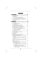
Installation 43 2.17 Hot Plug and Hot Swap Functions for SATA / SATAII HDDs 44 2.18 SATA / SATAII HDD Hot Plug Feature and Operation Guide 45 2.19 Driver Installation Guide 47 2.20 Installing Windows® XP / XP 64-bit / VistaTM / VistaTM 64-bit With RAID Functions 47 2.20.1 Installing Windows® XP - ASRock P55 Extreme | User Manual - Page 4
Health Event Monitoring Screen 69 3.6 Boot Screen 70 3.6.1 Boot Settings Configuration 70 3.7 Security Screen 71 3.8 Exit Screen 72 4 Software Support 73 4.1 Install Operating System 73 4.2 Support CD Information 73 4.2.1 Running Support CD 73 4.2.2 Drivers Menu 73 4.2.3 Utilities Menu 73 - ASRock P55 Extreme | User Manual - Page 5
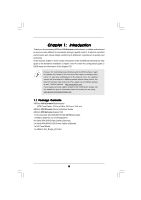
guide to BIOS setup and information of the Support CD. Because the motherboard specifications and the BIOS software might be updated, the content of this manual will be subject to change without notice. In case any modifications of this manual occur, the updated version will be available on ASRock - ASRock P55 Extreme | User Manual - Page 6
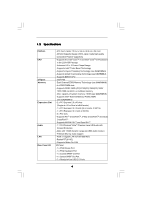
1.2 Specifications Platform CPU Chipset Memory Expansion Slot Audio LAN Rear Panel I/O - ATX Form Factor: 12.0-in x 9.6-in, 30.5 cm x 24.4 cm - All Solid Capacitor design (100% Japan-made high-quality Conductive Polymer Capacitors) - Supports the Intel® CoreTM i7 and Intel® CoreTM i5 Processors in - ASRock P55 Extreme | User Manual - Page 7
, VTT Voltage Multi-adjustment - Supports I. O. T. (Intelligent Overclocking Technology) - Supports Smart BIOS - Drivers, Utilities, AntiVirus Software (Trial Version) - ASRock OC Tuner (see CAUTION 9) - Intelligent Energy Saver (see CAUTION 10) - Instant Boot - ASRock Instant Flash (see CAUTION 11 - ASRock P55 Extreme | User Manual - Page 8
This motherboard supports Untied Overclocking Technology. Please read "Untied Overclocking Technology" on page 53 for details. 3. This motherboard supports Dual Channel Memory Technology. Before you implement Dual Channel Memory Technology, make sure to read the installation guide of memory modules - ASRock P55 Extreme | User Manual - Page 9
ASRock website: http://www.asrock.com/feature/IES/index.html 11. ASRock Instant Flash is a BIOS flash utility embedded in Flash ROM. This convenient BIOS update tool allows you to update system BIOS adopt two different CPU cooler types, Socket LGA 775 and LGA 1156. Please be noticed that not all the - ASRock P55 Extreme | User Manual - Page 10
Intel -N26-896H-B LEADTEK GTX 275 Chipset Name Driver GeForce 8500 GT GeForce 8600 GT supported under Windows® XP / XP 64-bit only. * For the latest updates of the supported PCI Express VGA card list for SLITM Mode, please visit our website for details. ASRock website: http://www.asrock.com/support - ASRock P55 Extreme | User Manual - Page 11
AX4670 512MD3-P Gecube GC-HD485PG3-E3 Chipset Name RADEON 4670 RADEON 4850 Driver Catalyst 9.6 Catalyst 9.6 * For the latest updates of the supported PCI Express VGA card list for CrossFireXTM Mode, please visit our website for details. ASRock website: http://www.asrock.com/support/index.htm 11 - ASRock P55 Extreme | User Manual - Page 12
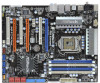
USB 2.0 T: USB4 Top: RJ-45 B: USB5 PWRBTN Top: SIDE SPK Center: REAR SPK Bottom: CTR BASS PWR_FAN1 CHA_FAN3 Top: LINE IN Center: FRONT Bottom: MIC IN 40 LAN PHY CPU_FAN1 P55 Extreme 39 PCIE1 38 PCI1 VIA VT6330 16Mb BIOS 37 CMOS CrossFireX Battery PCIE2 36 1394a Intel - ASRock P55 Extreme | User Manual - Page 13
1.7 I/O Panel 1 2 3 4 5 69 7 10 8 11 18 17 16 15 1 PS/2 Mouse Port (Green) 2 Coaxial SPDIF Out Port 3 USB 2.0 Port (USB6) 4 IEEE 1394 Port (IEEE 1394) * 5 LAN RJ-45 Port 6 Side Speaker (Gray) 7 Rear Speaker (Black) 8 Central / Bass (Orange) 9 Line In (Light Blue) 14 13 12 ** 10 11 12 13 14 - ASRock P55 Extreme | User Manual - Page 14
settings. 1. Unplug the power cord from the wall socket before touching any component. 2. To avoid damaging the motherboard components due to static electricity, NEVER place your motherboard directly on the carpet or the like. Also remember to use a grounded wrist strap or touch a safety grounded - ASRock P55 Extreme | User Manual - Page 15
Installation For the installation of Intel 1156-Pin CPU, please follow the steps below. Load Plate Load Lever Contact Array Socket Body 1156-Pin Socket Overview Before you insert the 1156-Pin CPU into the socket, cap. 2. This cap must be placed if returning the motherboard for after service. 15 - ASRock P55 Extreme | User Manual - Page 16
Heat Sink) up. Locate Pin1 and the two orientation key notches. orientation key notch alignment key Pin1 Pin1 orientation key notch 1156-Pin CPU alignment key 1156-Pin Socket For proper inserting, please ensure to match the two orientation key notches of the CPU with the two alignment keys - ASRock P55 Extreme | User Manual - Page 17
with fan operation or contact other components. Please be noticed that this motherboard supports Combo Cooler Option (C.C.O.), which provides the flexible option to adopt two different CPU cooler types, Socket LGA 775 and LGA 1156. The white throughholes are for Socket LGA 1156 CPU fan. 17 - ASRock P55 Extreme | User Manual - Page 18
2.5 Installation of Memory Modules (DIMM) This motherboard provides four 240-pin DDR3 (Double Data Rate 3) DIMM slots, and supports Dual Channel Memory Technology. For dual channel configuration, you always need to install identical (the same brand, speed, size and chiptype) DDR3 DIMM pair in the - ASRock P55 Extreme | User Manual - Page 19
matches the break on the slot. notch break notch break The DIMM only fits in one correct orientation. It will cause permanent damage to the motherboard and the DIMM if you force the DIMM into the slot at incorrect orientation. Step 3. Firmly insert the DIMM into the slot until the retaining - ASRock P55 Extreme | User Manual - Page 20
lane width cards, such as Gigabit LAN card, SATA2 card, etc., or used to install PCI Express graphics cards to support 3-Way CrossFireXTM function. 1. In the installation. Step 2. Remove the system unit cover (if your motherboard is already installed in a chassis). Step 3. Remove the bracket facing - ASRock P55 Extreme | User Manual - Page 21
Guide This motherboard supports NVIDIA® SLITM and Quad SLITM (Scalable Link Interface) technology that allows you to install up to two identical PCI Express x16 graphics cards. Currently, NVIDIA® SLITM technology supports card driver supports NVIDIA® SLITM technology. Download the driver from - ASRock P55 Extreme | User Manual - Page 22
Step3. Align and insert ASRock SLI_Bridge_2S Card to the goldfingers on each graphics card. Make sure ASRock SLI_Bridge_2S Card is firmly in place. ASRock SLI_Bridge_2S Card Step4. Connect a VGA cable or a DVI cable to the monitor connector or the DVI connector of the graphics card that is inserted - ASRock P55 Extreme | User Manual - Page 23
Installation and Setup Install the graphics card drivers to your system. After that, you can enable the MultiGraphics Processing Unit (GPU) feature in the NVIDIA® nView system tray utility. Please follow the below procedures to enable the multi-GPU feature. For Windows® XP / XP 64-bit OS: (For - ASRock P55 Extreme | User Manual - Page 24
item, please select Enable SLI. And click Apply. F. Reboot your system. G. You can freely enjoy the benefit of SLITM or Quad SLITM feature. * SLITM appearing here is a registered trademark of NVIDIA® Technologies Inc., and is used only for identification or explanation and to the owners - ASRock P55 Extreme | User Manual - Page 25
feature is supported with Windows® XP with Service Pack 2 and VistaTM OS. 3-Way CrossFireXTM and Quad CrossFireXTM feature are supported with Windows® VistaTM OS only. Please check AMD website for ATITM CrossFireXTM driver updates ATITM graphics card manuals for detailed installation guide. Step 1. - ASRock P55 Extreme | User Manual - Page 26
Bridge is provided with the graphics card you purchase, not bundled with this motherboard. Please refer to your graphics card vendor for details.) CrossFire Bridge or Step 3. Connect the DVI monitor cable to the DVI connector on the Radeon graphics card on PCIE1 slot. (You may use the DVI - ASRock P55 Extreme | User Manual - Page 27
Bridge is provided with the graphics card you purchase, not bundled with this motherboard. Please refer to your graphics card vendor for details.) CrossFire Bridge Step 3. Connect the DVI monitor cable to the DVI connector on the Radeon graphics card on PCIE1 slot. (You may use the DVI to - ASRock P55 Extreme | User Manual - Page 28
utility to uninstall any previously installed Catalyst drivers prior to installation. Please check AMD website for ATITM driver updates. Step 3. Step 4. Step 5. Install the required drivers to your system. For Windows® XP OS: A. ATITM recommends Windows® XP Service Pack 2 or higher to be installed - ASRock P55 Extreme | User Manual - Page 29
feature. * CrossFireXTM appearing here is a registered trademark of ATITM Technologies Inc., and is used only for identification or explanation and to the owners' benefit, without intent to infringe. * For further information of ATITM CrossFireXTM technology, please check AMD website for updates - ASRock P55 Extreme | User Manual - Page 30
Surround Display Feature This motherboard supports Surround Display upgrade. With the external add-on PCI Express VGA cards, you can easily enjoy the benefits of Surround Display feature. For the detailed instruction, please refer to the document at the following path in the Support CD: ..\ Surround - ASRock P55 Extreme | User Manual - Page 31
) (39-pin IDE1, see p.12 No. 12) PIN1 IDE1 connect the blue end to the motherboard connect the black end to the IDE devices 80-conductor ATA 66/100/133 cable Note: Please refer to the instruction of your IDE device vendor for the details. Serial ATAII Connectors (SATAII_1_2: see p.12, No - ASRock P55 Extreme | User Manual - Page 32
to the power connector of the power supply. Besides seven default USB 2.0 ports on the I/O panel, there are three USB 2.0 headers on this motherboard. Each USB 2.0 header can support two USB 2.0 ports. This connector supports a Trusted Platform Module (TPM) system, which can securely store keys - ASRock P55 Extreme | User Manual - Page 33
sources such as a CD-ROM, DVD-ROM, supports Jack Sensing, but the panel wire on the chassis must support HDA to function correctly. Please follow the instruction in our manual and chassis manual . E. Enter BIOS Setup Utility. Enter Advanced Settings, and then select Chipset Configuration. Set - ASRock P55 Extreme | User Manual - Page 34
CPU fan cable 2 +12V 3 CPU_FAN_SPEED to this connector and match 4 FAN_SPEED_CONTROL the black wire to the ground pin. Though this motherboard provides 4-Pin CPU fan (Quiet Fan) support, the 3-Pin CPU fan still can work successfully even without the fan speed control function. If you plan to - ASRock P55 Extreme | User Manual - Page 35
one default IEEE 1394 port on the I/O panel, there is one IEEE 1394 header (FRONT_1394) on this motherboard. This IEEE 1394 header can support one IEEE 1394 port. This COM1 header supports a serial port module. HDMI_SPDIF Header (3-pin HDMI_SPDIF1) (see p.12 No. 30) 1 GND SPDIFOUT +5V HDMI_SPDIF - ASRock P55 Extreme | User Manual - Page 36
HDMI_SPDIF Cable (Optional) C B A Please connect the black end (A) of HDMI_SPDIF cable to the HDMI_SPDIF header on the motherboard. Then connect the white end (B or C) of HDMI_SPDIF cable to the HDMI_SPDIF connector of HDMI VGA card. A. black end +5V SPDIFOUT GND B. white end (2-pin) C. - ASRock P55 Extreme | User Manual - Page 37
2.12 Smart Switches This motherboard has three smart switches: power switch, reset switch and clear CMOS switch, allowing users to quickly turn on/off or reset the system or clear - ASRock P55 Extreme | User Manual - Page 38
sizing in Bootblock code. Do additional chipset initialization. Re-enable CACHE. Verify that flat mode is enabled. Test base 512KB memory. Adjust policies and cache first 8MB. Set stack. Bootblock code is copied from ROM to lower system memory and control is given to it. BIOS now executes out of - ASRock P55 Extreme | User Manual - Page 39
in KBC port. Testing and initialization of different Input Devices. Also, update the Kernel Variables. Traps the INT09h vector, so that the POST INT09h handler gets control for IRQ1. Uncompress all available language, BIOS logo, and Silent logo modules. Early POST initialization of chipset registers - ASRock P55 Extreme | User Manual - Page 40
needed. 52 Updates CMOS memory size from memory found in memory test. Allocates memory for Extended BIOS Data Area from base memory. 60 Initializes the ADM module. AB Prepare BBS for Int 19 boot. AC End of POST initialization of chipset registers. B1 Save system context for ACPI. 00 - ASRock P55 Extreme | User Manual - Page 41
motherboard with a HDMI_SPDIF header. This motherboard motherboard. For the proper installation of HDMI VGA card, please refer to the installation guide manual of HDMI VGA card vendor. Incorrect connection may cause permanent damage to this motherboard Otherwise, the motherboard and the user manual for - ASRock P55 Extreme | User Manual - Page 42
please remove the jumpers from pin 3 and pin 4. HITACHI Please use the Feature Tool, a DOS-bootable tool, for changing various ATA features. Please visit HITACHI's website for details: http://www.hitachigst.com/hdd/support/download.htm The above examples are just for your reference. For different - ASRock P55 Extreme | User Manual - Page 43
adopts Intel® P55 chipset that supports Serial ATA (SATA) / Serial ATAII (SATAII) hard disks and RAID (RAID 0, RAID 1, RAID 10, RAID 5, and Intel Matrix Storage) functions. You may install SATA / SATAII hard disks on this motherboard for internal storage devices. This section will guide you - ASRock P55 Extreme | User Manual - Page 44
2.17 Hot Plug and Hot Swap Functions for SATA / SATAII HDDs This motherboard supports Hot Plug and Hot Swap functions for SATA / SATAII in RAID / AHCI mode. Intel® P55 chipset provides hardware support for Advanced Host controller Interface (AHCI), a new programming interface for SATA host - ASRock P55 Extreme | User Manual - Page 45
SATA / SATAII HDD Hot Plug. * The SATA / SATAII Hot Plug feature might not be supported by the chipset because of its limitation, the SATA / SATAII Hot Plug support information of our motherboard is indicated in the product spec on our website: www.asrock.com 2. Make sure your SATA / SATAII HDD can - ASRock P55 Extreme | User Manual - Page 46
cable to (White) to the power supply 1x4-pin cable. the motherboard's SATAII connector. SATA power cable 1x4-pin power connector (White) Step attention, before you process the Hot Unplug: Please do follow below instruction sequence to process the Hot Unplug, improper procedure will cause the SATA - ASRock P55 Extreme | User Manual - Page 47
follow below steps. STEP 1: Set up BIOS. A. Enter BIOS SETUP UTILITY Advanced screen B. Set the option "SATAII Operation Mode" to [RAID]. STEP 2: Make a SATA / SATAII Driver Diskette. Storage Configuration. A. Insert the Support CD into your optical drive to boot your system. B. During POST at - ASRock P55 Extreme | User Manual - Page 48
in the support CD, "Guide to Intel Matrix Storage Manager", which is located in the folder at the following path: .. \ Intel Matrix Storage Manager Information If you want to use "Intel Matrix Storage Manager" in Windows® environment, please install "SATAII driver" from the Support CD again so - ASRock P55 Extreme | User Manual - Page 49
-bit. 5. Finish the Windows® installation and install all necessary drivers. 6. Install the Intel(R) Matrix Storage Manager software via the CD-ROM included with your motherboard or after downloading it from the Internet. This will add the Intel(R) Matrix Storage Console which can be used to manage - ASRock P55 Extreme | User Manual - Page 50
the instruction to install Windows® VistaTM / VistaTM 64-bit OS on your system. When you see "Where do you want to install Windows?" page, please insert the ASRock Support CD into your optical drive, and click the "Load Driver" button on the left on the bottom to load the Intel® RAID drivers. Intel - ASRock P55 Extreme | User Manual - Page 51
beginning of Windows® setup, press F6 to install a thirdparty AHCI driver. When prompted, insert the SATA / SATAII driver diskette containing the Intel® AHCI driver. After reading the floppy disk, the driver will be presented. Select the driver to install according to the mode you choose and the OS - ASRock P55 Extreme | User Manual - Page 52
the instruction to install Windows® VistaTM / VistaTM 64-bit OS on your system. When you see "Where do you want to install Windows?" page, please insert the ASRock Support CD into your optical drive, and click the "Load Driver" button on the left on the bottom to load the Intel® AHCI drivers. Intel - ASRock P55 Extreme | User Manual - Page 53
Technology This motherboard supports Untied Overclocking Technology, which means during overclocking, FSB enjoys better margin due to fixed PCI / PCIE buses. Before you enable Untied Overclocking function, please enter "Overclock Mode" option of BIOS setup to set the selection from [Auto] to [Manual - ASRock P55 Extreme | User Manual - Page 54
selections: Main To set up the system time/date information OC Tweaker To set up overclocking features Advanced To set up the advanced BIOS features H/W Monitor To display current hardware status Boot To set up the default system device to locate and load the Operating System Security To - ASRock P55 Extreme | User Manual - Page 55
H/W Monitor Boot Security Exit System Overview System Time System Date [14:00:09] [Thu 06/04/2009] BIOS Version : P55 Extreme P1.00 Processor Type : Intel (R) Core (TM) CPU 860 @ 2.80GHz (64bit) Processor Speed : 2800MHz Microcode Update : 106E5/3 Cache Size : 8192KB Total Memory DDR3_A2 - ASRock P55 Extreme | User Manual - Page 56
Tweaker screen, you can set up overclocking features. BIOS SETUP UTILITY Main OC Tweaker Advanced H/W Monitor Boot Security Exit OC Tweaker Settings Load CPU EZ OC Setting Load Memory EZ OC Setting Overclock Mode BCLK Frequency (MHz) PCIE Frequency (MHz) Boot Failure Guard Spread Spectrum [Press - ASRock P55 Extreme | User Manual - Page 57
Auto]. DRAM Frequency If [Auto] is selected, the motherboard will detect the memory module(s) inserted and assigns appropriate frequency automatically. You may Auto]. DRAM Timing Control Use this item to control DRAM Timing. BIOS SETUP UTILITY Advanced DRAM Timing Control DRAM tCL DRAM tRCD DRAM - ASRock P55 Extreme | User Manual - Page 58
VDrop Control Use this to enable or disable ASRock VDrop control. Configuration options: [With VDrop] and [Without VDrop]. The default value is [With VDrop]. CPU Voltage Use this to select CPU Voltage. Configuration options: [Auto], [Manual] and [Overdrive Offset]. The default value is [Auto]. DRAM - ASRock P55 Extreme | User Manual - Page 59
in below sections may cause system to malfunction. CPU Configuration Chipset Configuration ACPI Configuration Storage Configuration PCIPnP Configuration Floppy Configuration SuperIO Configuration USB Configuration BIOS Update Utility ASRock Instant Flash Select Screen Select Item Enter Go to Sub - ASRock P55 Extreme | User Manual - Page 60
(NX) Memory Protection" can prevent data pages from being used by malicious software to execute code. This option will be hidden if the current CPU does not support No-Excute Memory Protection. Hyper Threading Technology To enable this feature, it requires a computer system with an Intel CoreTM i7 - ASRock P55 Extreme | User Manual - Page 61
[Enabled]. This item will be hidden if the current CPU does not support Intel (R) SpeedStep(tm) tech.. Please note that enabling this function may reduce CPU of both cores' requests, portraying a single CPU entity to the chipset power management hardware and flows. Thus, software can manage each - ASRock P55 Extreme | User Manual - Page 62
BIOS SETUP UTILITY Advanced Chipset Settings Memory Remap Feature Primary Graphics Adapter Onboard HD Audio Front Panel OnBoard Lan Onboard 1394 [Disabled] [PCI] [Auto] [Enabled] [Enabled] [Enabled] Intelligent Energy Saver [Disabled] Intel VT-d Configuration ENABLE: Allow remapping - ASRock P55 Extreme | User Manual - Page 63
BIOS SETUP UTILITY Advanced ACPI Configuration Suspend To RAM Restore on AC/Power Loss Ring-In Power On PCI Devices Power On PS / 2 Keyboard Power On RTC Alarm Power On ACPI HPET Table EUP Support disable the Suspend-toRAM feature. Select [Auto] will enable this feature if the OS supports it. If you - ASRock P55 Extreme | User Manual - Page 64
to use this motherboard to submit Windows® VistaTM certification. 3.4.4 Storage Configuration BIOS SETUP UTILITY Advanced Power Management" will appear. AHCI (Advanced Host Controller Interface) supports NCQ and other new features that will improve SATA disk performance but IDE mode does not - ASRock P55 Extreme | User Manual - Page 65
the example in the following instruction. BIOS SETUP UTILITY Advanced Primary IDE 40.0 GB :Supported :16Sectors :4 :MultiWord DMA-2 :Ultra DMA-5 :Supported [Auto] [ to active. [CD/DVD]: This is used for IDE CD/DVD drives. [ARMD this item is [Auto]. If this feature is enabled, it will enhance hard - ASRock P55 Extreme | User Manual - Page 66
(Self-Monitoring, Analysis, and Reporting Technology) feature. Configuration options: [Disabled], [Auto], [Enabled]. 32-Bit Data Transfer Use this item to enable 32-bit access to maximize the IDE hard disk data transfer rate. AHCI CD/DVD Boot Time Out Some SATA CD / DVD in AHCI mode need to wait - ASRock P55 Extreme | User Manual - Page 67
Help Load Defaults Save and Exit Exit v02.54 (C) Copyright 1985-2005, American Megatrends, Inc. 3.4.7Super IO Configuration BIOS SETUP UTILITY Advanced Configure Super IO Chipset OnBoard Floppy Controller Serial Port Address Infrared Port Address [Enabled] [3F8 / IRQ4] [Disabled] Allow - ASRock P55 Extreme | User Manual - Page 68
3.4.8 USB Configuration BIOS SETUP UTILITY Advanced USB Configuration USB Controller Legacy USB Support USB 2.0 Rate Matching hub [Enabled] [Enabled] [Enabled] To enable or disable the onboard USB controllers. +F1 F9 F10 ESC Select Screen Select Item Change Option General Help Load Defaults - ASRock P55 Extreme | User Manual - Page 69
motherboard temperature, CPU fan speed, chassis fan speed, and the critical voltage. BIOS SETUP UTILITY Main OC Tweaker Advanced H/W Monitor Boot to set the chassis fan 1 speed. Configuration options: [Full On] and [Manual mode]. The default is value [Full On]. Chassis Fan 2 Setting This allows you - ASRock P55 Extreme | User Manual - Page 70
Exit ESC Exit v02.54 (C) Copyright 1985-2005, American Megatrends, Inc. 3.6.1 Boot Settings Configuration BIOS SETUP UTILITY Boot Boot Settings Configuration Full Screen Logo AddOn ROM Display Boot Logo Boot From Onboard LAN Bootup Num-Lock [Enabled] [Enabled] [Auto] [Disabled] [On] Disabled - ASRock P55 Extreme | User Manual - Page 71
[Scenery] and [ASRock]. The default value is [Auto]. Boot From Onboard LAN Use this item to enable or disable the Boot From Onboard LAN feature. Boot Up Num-Lock you may also clear it. BIOS SETUP UTILITY Main OC Tweaker Advanced H/W Monitor Boot Security Exit Security Settings Supervisor Password - ASRock P55 Extreme | User Manual - Page 72
SETUP UTILITY Main OC Tweaker Advanced H/W Monitor Boot Security Exit Exit Options Save Changes and Exit Discard Changes and Exit Discard Changes Load BIOS Defaults Load Performance Setup Default (IDE/SATA) Load Performance Setup AHCI Mode Load Performance Setup RAID Mode Load Power Saving Setup - ASRock P55 Extreme | User Manual - Page 73
information. 4.2 Support CD Information The Support CD that came with the motherboard contains necessary drivers and useful utilities that enhance the motherboard features. 4.2.1 Running The Support CD To begin using the support CD, insert the CD into your CD-ROM drive. The CD automatically displays
-
 1
1 -
 2
2 -
 3
3 -
 4
4 -
 5
5 -
 6
6 -
 7
7 -
8
-
9
-
10
-
11
-
12
-
13
-
14
-
15
-
16
-
17
-
18
-
19
-
20
-
21
-
22
-
23
-
24
-
25
-
26
-
27
-
28
-
29
-
30
-
31
-
32
-
33
-
34
-
35
-
36
-
37
-
38
-
39
-
40
-
41
-
42
-
43
-
44
-
45
-
46
-
47
-
48
-
49
-
50
-
51
-
52
-
53
-
54
-
55
-
56
-
57
-
58
-
59
-
60
-
61
-
62
-
63
-
64
-
65
-
66
-
67
-
68
-
69
-
70
-
71
-
72
-
73
 |
 |

1
P55 Extreme
User Manual
Version 1.
1
Published August 2009
Copyright©2009 ASRock INC. All rights reserved.