ASRock P55 Extreme Quick Installation Guide
ASRock P55 Extreme Manual
 |
View all ASRock P55 Extreme manuals
Add to My Manuals
Save this manual to your list of manuals |
ASRock P55 Extreme manual content summary:
- ASRock P55 Extreme | Quick Installation Guide - Page 1
by ASRock. ASRock assumes no responsibility for any errors or omissions that may appear in this guide. With respect to the contents of this guide, ASRock does ASRock Website: http://www.asrock.com Published August 2009 Copyright©2009 ASRock INC. All rights reserved. 1 ASRock P55 Extreme Motherboard - ASRock P55 Extreme | Quick Installation Guide - Page 2
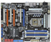
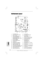
Motherboard Layout English 1 PS2_USB_PWR1 Jumper 22 Dr. Debug (LED) 2 ATX 12V Power Connector (ATX12V1) 23 USB 2.0 Header (USB8_9, Blue) 3 1156-Pin CPU Socket 24 Intel P55 Chipset 4 Chassis Fan Connector (CHA_FAN3) 25 Front Panel IEEE 1394 Header 5 2 x 240-pin DDR3 DIMM Slots (FRONT_1394, - ASRock P55 Extreme | Quick Installation Guide - Page 3
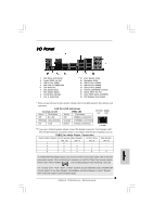
USB 2.0 Ports (USB45) USB 2.0 Ports (USB23) USB 2.0 Ports (USB01) Powered eSATAII/USB Connector Optical SPDIF Out Port Clear CMOS Switch (CLRCBTN) PS/2 Keyboard Port (Purple) * There are two LED next to the LAN HDA Audio 2nd output" to use front panel audio. 3 ASRock P55 Extreme Motherboard English - ASRock P55 Extreme | Quick Installation Guide - Page 4
information about the model you are using. www.asrock.com/support/index.asp 1.1 Package Contents ASRock P55 Extreme Motherboard (ATX Form Factor: 12.0-in x 9.6-in, 30.5 cm x 24.4 cm) ASRock P55 Extreme Quick Installation Guide ASRock P55 Extreme Support CD 1 x 80-conductor Ultra ATA 66/100/133 IDE - ASRock P55 Extreme | Quick Installation Guide - Page 5
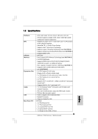
Blu-ray audio support - PCIE x1 Gigabit LAN 10/100/1000 Mb/s - Realtek RTL8111DL - Supports Wake-On-LAN I/O Panel - 1 x PS/2 Mouse Port - 1 x PS/2 Keyboard Port - 1 x Coaxial SPDIF Out Port - 1 x Optical SPDIF Out Port - 7 x Ready-to-Use USB 2.0 Ports 5 ASRock P55 Extreme Motherboard English - ASRock P55 Extreme | Quick Installation Guide - Page 6
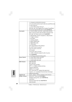
) - Supports Smart BIOS Support CD - Drivers, Utilities, AntiVirus Software (Trial Version) Unique Feature - ASRock OC Tuner (see CAUTION 9) - Intelligent Energy Saver (see CAUTION 10) - Instant Boot - ASRock Instant Flash (see CAUTION 11) - Hybrid Booster: 6 ASRock P55 Extreme Motherboard - ASRock P55 Extreme | Quick Installation Guide - Page 7
is supported through overclocking. 6. For microphone input, this motherboard supports both stereo and mono modes. For audio output, this motherboard supports 2-channel, 4-channel, 6-channel, and 8-channel modes. Please check the table on page 3 for proper connection. English 7 ASRock P55 Extreme - ASRock P55 Extreme | Quick Installation Guide - Page 8
operation procedures of Intelligent Energy Saver. ASRock website: http://www.asrock.com/feature/IES/index.html 11. ASRock Instant Flash is a BIOS flash utility embedded in Flash ROM. This convenient BIOS update tool allows you to update system BIOS without entering operating systems first like MS - ASRock P55 Extreme | Quick Installation Guide - Page 9
Intel Chipset Name Driver supported under Windows® XP / XP 64-bit only. * For the latest updates of the supported PCI Express VGA card list for SLITM Mode, please visit our website for details. ASRock website: http://www.asrock.com/support/index.htm English 9 ASRock P55 Extreme Motherboard - ASRock P55 Extreme | Quick Installation Guide - Page 10
Chipset Name RADEON 4670 RADEON 4850 Driver Catalyst 9.6 Catalyst 9.6 * For the latest updates of the supported PCI Express VGA card list for CrossFireXTM Mode, please visit our website for details. ASRock website: http://www.asrock.com/support/index.htm English 10 ASRock P55 Extreme Motherboard - ASRock P55 Extreme | Quick Installation Guide - Page 11
you insert the 1156-Pin CPU into the socket, please check if the CPU surface is unclean or if there is any bent pin on the socket. Do not force to insert the CPU into the socket if above situation is found. Otherwise, the CPU will be seriously damaged. English 11 ASRock P55 Extreme Motherboard - ASRock P55 Extreme | Quick Installation Guide - Page 12
be placed if returning the motherboard for after service. Step 3. Insert the 1156-Pin CPU: Step 3-1. 1156-Pin Socket 1156-Pin CPU For proper inserting, please ensure to match the two orientation key notches of the CPU with the two alignment keys of the socket. 12 ASRock P55 Extreme Motherboard - ASRock P55 Extreme | Quick Installation Guide - Page 13
components. et Please be noticed that this motherboard supports Combo Cooler Option (C.C.O.), which provides the flexible option to adopt two different CPU cooler types, Socket LGA 775 and LGA 1156. The white throughholes are for Socket LGA 1156 CPU fan. 13 ASRock P55 Extreme Motherboard English - ASRock P55 Extreme | Quick Installation Guide - Page 14
the Dual Channel Memory Technology. 3. It is not allowed to install a DDR or DDR2 memory module into DDR3 slot;otherwise, this motherboard and DIMM may be damaged. 4. Please install the memory module into the white slot (DDR3_B1) for the first priority. English 14 ASRock P55 Extreme Motherboard - ASRock P55 Extreme | Quick Installation Guide - Page 15
It will cause permanent damage to the motherboard and the DIMM if you force the DIMM into the slot at incorrect orientation. Step 3. Firmly insert the DIMM into the slot until the retaining clips at both ends fully snap back in place and the DIMM is properly seated. 15 ASRock P55 Extreme Motherboard - ASRock P55 Extreme | Quick Installation Guide - Page 16
used for PCI Express x1 lane width cards, such as Gigabit LAN card, SATA2 card, etc., or used to install PCI Express graphics cards to support 3-Way CrossFireXTM function. 1. In single VGA card mode, it chassis with screws. Step 6. Replace the system cover. 16 ASRock P55 Extreme Motherboard English - ASRock P55 Extreme | Quick Installation Guide - Page 17
cards that are NVIDIA® certified. 2. Make sure that your graphics card driver supports NVIDIA® SLITM technology. Download the driver from NVIDIA® website (www.nvidia.com). 3. Make sure that your power power source to the PCI Express graphics cards. 17 ASRock P55 Extreme Motherboard English - ASRock P55 Extreme | Quick Installation Guide - Page 18
PCIE1 slot. 2.5.2 Driver Installation and Setup Install the graphics card drivers to your system. After that, you can enable the MultiGraphics Processing Unit (GPU) feature in the NVIDIA® your system. D. You can freely enjoy the benefit of SLITM feature. 18 ASRock P55 Extreme Motherboard English - ASRock P55 Extreme | Quick Installation Guide - Page 19
. G. You can freely enjoy the benefit of SLITM or Quad SLITM feature. * SLITM appearing here is a registered trademark of NVIDIA® Technologies Inc., and is used only for identification or explanation and to the owners' benefit, without intent to infringe. 19 ASRock P55 Extreme Motherboard English - ASRock P55 Extreme | Quick Installation Guide - Page 20
in the future, please refer to ATITM graphics card manuals for detailed installation guide. Step 1. Insert one Radeon graphics card into PCIE1 slot and the other Radeon graphics card to PCIE3 slot. Make sure that the cards are properly seated on the slots. 20 ASRock P55 Extreme Motherboard English - ASRock P55 Extreme | Quick Installation Guide - Page 21
provided with the graphics card you purchase, not bundled with this motherboard. Please refer to your graphics card vendor for details.) CrossFire Bridge or Step 3. Connect the DVI monitor cable to the DVI the cards are properly seated on the slots. English 21 ASRock P55 Extreme Motherboard - ASRock P55 Extreme | Quick Installation Guide - Page 22
check AMD website for details. Restart your computer. Install the VGA card drivers to your system, and restart your computer. Then you will find "ATI Catalyst Control Center" on your Windows® taskbar. (Driver Version: 8-12_vista32_dd_ccc_wdm_enu_72275.exe) ASRock P55 Extreme Motherboard English - ASRock P55 Extreme | Quick Installation Guide - Page 23
to enjoy the benefit of CrossFireXTM feature. Step 7. You can freely enjoy the benefit of CrossFireXTM, 3-Way CrossFireXTM or Quad CrossFireXTM feature. * CrossFireXTM appearing here is technology, please check AMD website for updates and details. 23 ASRock P55 Extreme Motherboard English - ASRock P55 Extreme | Quick Installation Guide - Page 24
for 5 seconds. However, please do not clear the CMOS right after you update the BIOS. If you need to clear the CMOS when you just finish updating the BIOS, you must boot up the system first, and then shut it down before you do the clearCMOS action. English 24 ASRock P55 Extreme Motherboard - ASRock P55 Extreme | Quick Installation Guide - Page 25
instruction of your IDE device vendor for the details. Serial ATAII Connectors (SATAII_1_2: see p.2, No. 14) (SATAII_3_4: see p.2, No. 15) (SATAII_5_6: see p.2, No. 16) These six Serial ATAII (SATAII) connectors support or the SATAII connector on this motherboard. 25 ASRock P55 Extreme Motherboard - ASRock P55 Extreme | Quick Installation Guide - Page 26
supply. Besides seven default USB 2.0 ports on the I/O panel, there are three USB 2.0 headers on this motherboard. Each USB 2.0 header can support two USB 2.0 ports. (9-pin . This header supports an optional wireless transmitting and receiving infrared module. 26 ASRock P55 Extreme Motherboard - ASRock P55 Extreme | Quick Installation Guide - Page 27
such as a CD-ROM, DVD-ROM supports Jack Sensing, but the panel wire on the chassis must support HDA to function correctly. Please follow the instruction in our manual and chassis manual BIOS Setup Utility. Enter Advanced Settings, and then select Chipset ASRock P55 Extreme Motherboard English - ASRock P55 Extreme | Quick Installation Guide - Page 28
3-Pin CPU fan to the CPU fan connector on this motherboard, please connect it to Pin 1-3. Pin 1-3 Connected 3-Pin Fan Installation ATX Power Connector (24-pin ATXPWR1) (see p.2, No. 9) 12 24 1 13 Please connect an ATX power supply to this connector. English 28 ASRock P55 Extreme Motherboard - ASRock P55 Extreme | Quick Installation Guide - Page 29
there is one IEEE 1394 header (FRONT_1394) on this motherboard. This IEEE 1394 header can support one IEEE 1394 port. This COM1 header supports a serial port module. HDMI_SPDIF Header HDMI_SPDIF header, connector of HDMI VGA card to this header. English 29 ASRock P55 Extreme Motherboard - ASRock P55 Extreme | Quick Installation Guide - Page 30
of HDMI VGA card. B. white end (2-pin) C. white end (3-pin) 2.10 Smart Switches This motherboard has three smart switches: power switch, reset switch and clear CMOS switch, allowing users to quickly turn on page 24 "Clear CMOS jumper" description instead. English 30 ASRock P55 Extreme Motherboard - ASRock P55 Extreme | Quick Installation Guide - Page 31
Uncompressed pointer for future use in PMM. Copying Main BIOS into memory. Leaves all RAM below 1MB Read-Write including E000 and F000 shadow areas but closing SMRAM. Restore CPUID value back into register. Give control to BIOS POST (ExecutePOSTKernel). English 31 ASRock P55 Extreme Motherboard - ASRock P55 Extreme | Quick Installation Guide - Page 32
adapter installed in the system that have optional ROMs. Initializes all the output devices. Allocate memory for ADM module and uncompress it. Give control to ADM module for initialization. Initialize language and font modules for ADM. Activate ADM module. ASRock P55 Extreme Motherboard English - ASRock P55 Extreme | Quick Installation Guide - Page 33
Uninstall POST INT1Ch vector and INT09h vector. Deinitializes the ADM module. AB Prepare BBS for Int 19 boot. AC End of POST initialization of chipset registers. B1 Save system context for ACPI. 00 Passes control to OS Loader (typically INT19h). English 33 ASRock P55 Extreme Motherboard - ASRock P55 Extreme | Quick Installation Guide - Page 34
below steps. Using SATA / SATAII HDDs without NCQ function STEP 1: Set up BIOS. A. Enter BIOS SETUP UTILITY Advanced screen Storage Configuration. B. Set the option "SATAII Operation Mode" to [IDE]. STEP 2: Install Windows® XP / XP 64-bit OS on your system. 34 ASRock P55 Extreme Motherboard English - ASRock P55 Extreme | Quick Installation Guide - Page 35
drivers are in the following path in our Support CD: .. \ I386 (For Windows® VistaTM OS) .. \ AMD64 (For Windows® VistaTM 64-bit OS) After that, please insert Windows® VistaTM / VistaTM 64-bit optical disk into the optical drive again to continue the installation. 35 ASRock P55 Extreme Motherboard - ASRock P55 Extreme | Quick Installation Guide - Page 36
your CD-ROM drive. It will display the Main Menu automatically if "AUTORUN" is enabled in your computer. If the Main Menu does not appear automatically, locate and double-click on the file "ASSETUP. EXE" from the BIN folder in the Support CD to display the menus. 36 ASRock P55 Extreme Motherboard - ASRock P55 Extreme | Quick Installation Guide - Page 37
benötigen, besuchen Sie bitte unsere Webseite: www.asrock.com/support/index.asp 1.1 Kartoninhalt ASRock P55 Extreme Motherboard (ATX-Formfaktor: 30.5 cm x 24.4 cm; 12.0 Zoll x 9.6 Zoll) ASRock P55 Extreme Schnellinstallationsanleitung ASRock P55 Extreme Support-CD Ein 80-adriges Ultra-ATA 66/100/133 - ASRock P55 Extreme | Quick Installation Guide - Page 38
® VistaTM Premium Niveau HD Audio mit dem Inhalt Schutz - DAC mit 110dB Aussteuerungsbereich (ALC890 Audio Codec) - Premium Blu-ray-Audio-Unterstützung - PCIE x1 Gigabit LAN 10/100/1000 Mb/s - Realtek RTL8111DL - Unterstützt Wake-On-LAN Deutsch 38 ASRock P55 Extreme Motherboard - ASRock P55 Extreme | Quick Installation Guide - Page 39
AMI BIOS - AMI legal BIOS mit Unterstützung für "Plug and Play" - ACPI 1.1-Weckfunktionen - JumperFree-Übertaktungstechnologie - SMBIOS 2.3.1 - Zentraleinheit, VCCM, SB, VTT Stromspannung Multianpassung - Unterstützt I. O. T. (Intelligente Übertakten Technologie) 39 ASRock P55 Extreme Motherboard - ASRock P55 Extreme | Quick Installation Guide - Page 40
äte Ihres Systems beschädigen. Es geschieht dann auf eigene Gefahr und auf Ihre Kosten. Wir übernehmen keine Verantwortung für mögliche Schäden, die aufgrund von Overclocking verursacht wurden. Deutsch 40 ASRock P55 Extreme Motherboard - ASRock P55 Extreme | Quick Installation Guide - Page 41
Seite 42 der "Bedienungsanleitung" auf der Support-CD, um Ihre SATAII-Festplatte dem SATAII -Anschluss verbinden. 8. Das Power Management für USB 2.0 arbeitet unter Microsoft® Windows® VistaTM 64 ASRock-Website: http://www.asrock.com/feature/IES/index.html 41 ASRock P55 Extreme Motherboard Deutsch - ASRock P55 Extreme | Quick Installation Guide - Page 42
BIOS-Setup-Menü Zugang zu ASRock Instant Flash. Sie brauchen dieses Werkzeug einfach nur zu starten und die neue BIOS-Datei auf Ihrem USB Socket LGA 775 und LGA 1156. Motherboard und eine EuP-fähige Stromversorgung erforderlich. Gemäß einer Empfehlung von Intel ASRock P55 Extreme Motherboard Deutsch - ASRock P55 Extreme | Quick Installation Guide - Page 43
) 1156-Pin Sockel Übersicht Bevor Sie die 1156-Pin CPU in den Sockel sitzen, prüfen Sie bitte, ob die CPU-Oberfläche sauber ist und keine der Kontakte verbogen sind. Setzen Sie die CPU nicht mit Gewalt in den Sockel, dies kann die CPU schwer beschädigen. Deutsch 43 ASRock P55 Extreme Motherboard - ASRock P55 Extreme | Quick Installation Guide - Page 44
mit dem IHS (Integrated Heat Sink - integrierter Kühlkörper) nach oben. Suchen Sie Pin 1 und die zwei Orientierungseinkerbungen. Orientierungskerbe Ausrichtungsmarkierung Pin1 Pin1 Ausrichtungsmarkierung 44 Orientierungskerbe 1156-Pin CPU 1156-Pin Sockel ASRock P55 Extreme Motherboard - ASRock P55 Extreme | Quick Installation Guide - Page 45
(IHS). Schritt 4-2. Drücken Sie leicht auf die Ladeplatte und schließen Sie den Ladehebel. Schritt 4-3. Sichern Sie Ladehebel und Ladeplatte mithilfe des Hebelverschlusses. 45 ASRock P55 Extreme Motherboard Deutsch - ASRock P55 Extreme | Quick Installation Guide - Page 46
dass dieses Motherboard die ComboKühleroption unterstützt, die eine flexible Möglichkeit zur Aufnahme von zwei verschiedenen CPU-Kühlertypen, Socket LGA 775 und LGA 1156, bietet. Das weiße Durchgangsloch ist für den CPULüfter im Socket LGA 1156 vorgesehen. 46 ASRock P55 Extreme Motherboard Deutsch - ASRock P55 Extreme | Quick Installation Guide - Page 47
nicht aktivieren. 3. Es ist nicht zulässig, DDR oder DDR2 in einen DDR3 Steckplatz zu installieren; andernfalls könnten Motherboard und DIMMs beschädigt werden. 4. Installieren Sie das Speichermodul für die erste Priorität im weißen Steckplatz (DDR3_B1). Deutsch 47 ASRock P55 Extreme Motherboard - ASRock P55 Extreme | Quick Installation Guide - Page 48
in die Steckplätze, so dass die Halteklammern an beiden Enden des Moduls einschnappen und das DIMM-Modul fest an Ort und Stelle sitzt. 48 ASRock P55 Extreme Motherboard - ASRock P55 Extreme | Quick Installation Guide - Page 49
-Karten mit x1 Lane-Breite-Karten verwendet, z.B. Gigabit LAN-Karte, SATA2-Karte. PCIE3 (PCIE x16-Steckplatz; orange Motherboard- Gehäuselüfteranschluss (CHA_FAN1 oder CHA_FAN2), wenn Sie mehrere Grafikkarten für eine bessere Wärmeumgebung verwenden. Deutsch 49 ASRock P55 Extreme Motherboard - ASRock P55 Extreme | Quick Installation Guide - Page 50
Derzeit wird die CrossFireXTMFunktion von den Betriebssystemen Windows® XP mit Service Pack 2 und VistaTM unterstützt. Die 3-Way CrossFireXTM- ATITM CrossFireXTM-Treiber-Updates gibt. Beachten Sie den detailliert erklärten Installationsablauf auf Seite 20. 50 ASRock P55 Extreme Motherboard Deutsch - ASRock P55 Extreme | Quick Installation Guide - Page 51
Sie nicht, den Jumper wieder zu entfernen, nachdem das CMOS gelöscht wurde. Wenn Sie den CMOS-Inhalt gleich nach dem Aktualisieren des BIOS löschen müssen, müssen Sie zuerst das System starten und dann wieder ausschalten, bevor Sie den CMOS-Inhalt löschen. 51 ASRock P55 Extreme Motherboard Deutsch - ASRock P55 Extreme | Quick Installation Guide - Page 52
Header und Anschlüsse. Wenn Sie Jumperkappen auf Header und Anschlüsse setzen, wird das Motherboard unreparierbar beschädigt! Anschluss für das Floppy-Laufwerk (33-Pin FLOPPY1) (siehe S.2 - das SATAII Verbindungsstück auf dieser Hauptplatine angeschlossen werden. 52 ASRock P55 Extreme Motherboard - ASRock P55 Extreme | Quick Installation Guide - Page 53
Zusätzlich zu den sieben üblichen USB 2.0-Ports an den I/O-Anschlüssen befinden sich drei USB 2.0Anschlussleisten am Motherboard. Pro USB 2.0Anschlussleiste werden zwei USB 2.0-Ports unterstützt. (9-pol. ein optionales, drahtloses Sendeund Empfangs-Infrarotmodul. 53 ASRock P55 Extreme Motherboard - ASRock P55 Extreme | Quick Installation Guide - Page 54
No. 32) Diese ermöglichen Ihnen Stereo-Signalquellen, wie z. B. CD1 CD-ROM, DVD-ROM, TV-Tuner oder MPEG-Karten mit Ihrem System zu Sie das BIOS-Setup-Dienstprogramm auf. Wechseln Sie zu Erweiterte Einstellungen und wählen Sie Chipset-Konfiguration. Setzen ren, dann 54 ASRock P55 Extreme Motherboard - ASRock P55 Extreme | Quick Installation Guide - Page 55
ohne Geschwindigkeitsregulierung. Wenn Sie einen dreipoligen CPU-Lüfter an den CPU-Lüferanschluss dieses Motherboards anschließen möchten, verbinden Sie ihn bitte mit den Pins 1 - 3. Pins 1-3 anschließen Lüfter mit dreipoligem Anschluss installieren 55 ASRock P55 Extreme Motherboard Deutsch - ASRock P55 Extreme | Quick Installation Guide - Page 56
- No. 9) 12 24 Verbinden Sie die ATXStromversorgung mit diesem Header. 1 13 Obwohl dieses Motherboard einen 24-pol. ATX-Stromanschluss 12 24 bietet, kann es auch mit einem modifizierten traditionellen 20 , um ein COM-Anschlussmodul zu unterstützen. Deutsch 56 ASRock P55 Extreme Motherboard - ASRock P55 Extreme | Quick Installation Guide - Page 57
HDMI_SPDIF-Kabels mit dem HDMI_SPDIF-Anschluss am Motherboard. Schließen Sie dann das weiße Ende (B oder C) des HDMI_SPDIF-Kabels an den HDMI_SPDIF-Anschluss der HDMI-VGA-Karte an. A. Schwarzes Ende B. Weißes Ende (zweipolig) C. Weißes Ende (dreipolig) Deutsch 57 ASRock P55 Extreme Motherboard - ASRock P55 Extreme | Quick Installation Guide - Page 58
2.10 Schnellschalter Dieses Motherboard besitzt drei Schnellschalter: Netzschalter, Rücksetzschalter (Reset) und CMOS löschen-Schalter, mit denen Benutzer das System auch auf die Beschreibung "Clear CMOS jumper" (CMOS löschen-Jumper) auf Seite 51 beziehen. Deutsch 58 ASRock P55 Extreme Motherboard - ASRock P55 Extreme | Quick Installation Guide - Page 59
1: BIOS einrichten. A. Rufen Sie das BIOS SETUP UTILITY auf, wählen Sie den „Advanced"- Bildschirm (Erweitert), dann „Storage Configuration". B. Stellen Sie "SATAII Operation Mode" auf [IDE]. SCHRITT 2: Installieren Sie Windows® XP / XP 64-Bit in Ihrem System. 59 ASRock P55 Extreme Motherboard - ASRock P55 Extreme | Quick Installation Guide - Page 60
auf der Support CD: .. \ I386 (Für Windows® VistaTM-Benutzer) .. \ AMD64 (Für Windows® VistaTM 64-Bit Benutzer) Legen Sie danach noch einmal die Windows® VistaTM / VistaTM 64-Bit optische Disc in das optische Laufwerk, um die Installation fortzusetzen. 60 ASRock P55 Extreme Motherboard Deutsch - ASRock P55 Extreme | Quick Installation Guide - Page 61
der Support-CD, um die Menüs aufzurufen. Das Setup-Programm soll es Ihnen so leicht wie möglich machen. Es ist menügesteuert, d.h. Sie können in den verschiedenen Untermenüs Ihre Auswahl treffen und die Programme werden dann automatisch installiert. 61 ASRock P55 Extreme Motherboard Deutsch - ASRock P55 Extreme | Quick Installation Guide - Page 62
asrock.com/support/index.asp 1.1 Contenu du paquet Carte mère ASRock P55 Extreme (Facteur de forme ATX: 12.0 pouces x 9.6 pouces, 30.5 cm x 24.4 cm) Guide d'installation rapide ASRock P55 Extreme CD de soutien ASRock P55 Extreme Un carte 2S_Pont_ASRock SLI 62 ASRock P55 Extreme Motherboard Français - ASRock P55 Extreme | Quick Installation Guide - Page 63
Audio avec protection de contenu - DAC avec une gamme dynamique 110dB (ALC890 Audio Codec) - Prise en charge de l'audio Premium Blu-ray - PCIE x1 Gigabit LAN 10/100/1000 Mb/s - Realtek RTL8111DL - Support du Wake-On-LAN 63 ASRock P55 Extreme Motherboard Français - ASRock P55 Extreme | Quick Installation Guide - Page 64
BIOS I/O Panel - 1 x port souris PS/2 - 1 x port clavier PS/2 - 1 x Port de sortie coaxial SPDIF - 1 x Port de sortie optique SPDIF - 7 x ports USB 2.0 par défaut - 1 x Connecteur eSATAII/USB alimenté - 1 x port LAN 0Go/s, supporte RAID BIOS AMI - BIOS AMI Français 64 ASRock P55 Extreme Motherboard - ASRock P55 Extreme | Quick Installation Guide - Page 65
d'Overclocking Intelligent) - Prise en charge du Smart BIOS CD d'assistance - Pilotes, utilitaires, logiciel anti-virus (Version d'essai) Caractéristique - Tuner ASRock OC (voir ATTENTION 9) unique - Économiseur d'énergie intelligent (voir ATTENTION 10) - l'Instant Boot - ASRock Instant - ASRock P55 Extreme | Quick Installation Guide - Page 66
, veuillez lire le Guide « Installation du disque dur SATAII » à la page 42 du « Manuel de l'utilisateur » qui se trouve sur le CD de support pour régler votre d'Intelligent Energy Saver. Site Web ASRock : http://www.asrock.com/feature/IES/index.html 66 ASRock P55 Extreme Motherboard Français - ASRock P55 Extreme | Quick Installation Guide - Page 67
teste de arranque POST ou premir a tecla para exibir o menu de configuração do BIOS para aceder ao ASRock Instant Flash. Execute esta ferramenta para guardar o novo ficheiro de BIOS numa unidade flash USB LGA 775 et LGA 1156 suggestions d'Intel', l' ASRock P55 Extreme Motherboard Français - ASRock P55 Extreme | Quick Installation Guide - Page 68
4. A chaque désinstallation de composant, placez-le sur un support antistatique ou dans son sachet d'origine. 5. Lorsque vous placez mère. 2.1 Installation du CPU Pour l'installation du processeur Intel 1156 broches, veuillez suivre la procédure ci-dessous. (Plaque ASRock P55 Extreme Motherboard - ASRock P55 Extreme | Quick Installation Guide - Page 69
en place si vous renvoyez la carte mère pour service après vente. Etape 3. Insérez le processeur 1156 broches : Etape 3-1. Tenez le processeur par ses bords trompeur Encoche d'orientation Processeur 1156 broches Détrompeur Socket 1156 broches ASRock P55 Extreme Motherboard broche 1 69 Français - ASRock P55 Extreme | Quick Installation Guide - Page 70
et dissipateur thermique Pour une installation correcte, veuillez vous reporter aux manuels d'instructions de votre ventilateur de processeur et de votre dissipateur thermique. L'exemple d'interface thermique au centre de IHS sur la surface du socket. Français 70 ASRock P55 Extreme Motherboard - ASRock P55 Extreme | Quick Installation Guide - Page 71
en charge l'option Combo Cooler Option (C.C.O.), qui offre un choix flexible pour adopter deux types différents de refroidisseurs de CPU, les sockets LGA 775 et LGA 1156. Les trous traversant blancs sont pour le ventilateur de CPU au socket LGA 1156. Français 71 ASRock P55 Extreme Motherboard - ASRock P55 Extreme | Quick Installation Guide - Page 72
des modules m émoire [DIMM] La carte mère P55 Extreme dispose de quatre emplacements DIMM DDR3 (Double Data Rate 3) de 240-broches, et supporte la Technologie de Mémoire à Canal Double. Pour installer le module de mémoire dans la fente blanche (DDR3_B1). Français 72 ASRock P55 Extreme Motherboard - ASRock P55 Extreme | Quick Installation Guide - Page 73
jusqu'à ce que les clips de maintien situés aux deux extrémités se ferment complètement et que le module DIMM soit inséré correctement. 73 ASRock P55 Extreme Motherboard - ASRock P55 Extreme | Quick Installation Guide - Page 74
PCIE x1; blanc) sert aux cartes PCI Express avec les cartes de largeur x1 voie, comme la carte Gigabit LAN, la carte SATA2. Le PCIE3 (slot PCIE x16; orange) sert aux cartes graphiques PCI Express de largeur x16 4. Fixez la carte sur le châssis à l'aide d'une vis. 74 ASRock P55 Extreme Motherboard - ASRock P55 Extreme | Quick Installation Guide - Page 75
, vous pouvez facilement jouir des avantages de la caractéristique de l'affichage Surround. Pour les instructions détaillées, veuillez vous reporter au document qui se trouve sur le chemin suivant dans le CD d'assistance : ..\ Surround Display Information 75 ASRock P55 Extreme Motherboard Français - ASRock P55 Extreme | Quick Installation Guide - Page 76
PS/2 ou USB de réveiller BIOS à jour. Si vous avez besoin d'effacer la CMOS lorsque vous avez fini de mettre le BIOS à jour, vous devez d'abord initialiser le système, puis le mettre hors tension avant de procéder à l'opération d'effacement de la CMOS. Français 76 ASRock P55 Extreme Motherboard - ASRock P55 Extreme | Quick Installation Guide - Page 77
mère vers le disque dur Câble ATA 66/100/133 80 conducteurs Note: Veuillez vous reporter aux instructions du fabricant de votre IDE périphérique pour les détails. Connecteurs Série ATAII (SATAII_1_2: voir p.2 SATAII ou au connecteur SATAII sur la carte mere. 77 ASRock P55 Extreme Motherboard - ASRock P55 Extreme | Quick Installation Guide - Page 78
option) connecter au connecteur d'alimentation du disque dur SATA connecter à l'unité d'alimentation électrique En-tête USB 2.0 (US12_13 br.9) (voir p.2 No. 19) (US10_11 br.9) (voir p.2 No. 21) Veuillez és numériques, et assure l'intégrité de la plate-forme. 78 ASRock P55 Extreme Motherboard - ASRock P55 Extreme | Quick Installation Guide - Page 79
p.2 No. 31) Cet en-tête supporte un module infrarouge optionnel de transfert et CD1 stéréo comme un CD-ROM, DVD-ROM, un correctement. Veuillez suivre les instructions dans notre manuel et dans l'utilitaire de configuration du BIOS. Saisir les Paramètres ASRock P55 Extreme Motherboard Français - ASRock P55 Extreme | Quick Installation Guide - Page 80
à la broche de terre. Veuillez connecter le câble de ventilateur d'UC sur ce connecteur et brancher le fil noir sur la broche de terre. 80 ASRock P55 Extreme Motherboard Français - ASRock P55 Extreme | Quick Installation Guide - Page 81
onnecteurs pour es correspondre oche de terre. ien que cette carte mère offre un support de (Ventilateur silencieux) ventilateur de CPU à 4 broches , le ventilateur de CPU sur cette carte mere. Le header de IEEE 1394 peut supporter un port de IEEE 1394. 81 ASRock P55 Extreme Motherboard Français - ASRock P55 Extreme | Quick Installation Guide - Page 82
émité blanche (B ou C) du câble HDMI_SPDIF au connecteur HDMI_SPDIF de la carte VGA HDMI. B. extrémité blanche (2 briches) C. extrémité blanche (3 briches) Français 82 ASRock P55 Extreme Motherboard - ASRock P55 Extreme | Quick Installation Guide - Page 83
passe de votre système ou vous référer plutôt à la description "Clear CMOS jumper (Cavalier d'effacement du CMOS)" de la page 76. Français 83 ASRock P55 Extreme Motherboard - ASRock P55 Extreme | Quick Installation Guide - Page 84
le BIOS. A. Accédez à BIOS SETUP UTILITY (Utilitaire de configuration BIOS) écran Avancé Configuration Storage. B. Réglez «SATAII Operation Mode « sur [IDE]. ETAPE 2 : Installez le système d'exploitation Windows® XP / XP 64 bits sur votre système. 84 ASRock P55 Extreme Motherboard Français - ASRock P55 Extreme | Quick Installation Guide - Page 85
CD Support: .. \ I386 (Pour les utilisateurs de Windows® VistaTM) .. \ AMD64 (Pour les utilisateurs de Windows® VistaTM 64-bits) Ensuite, veuillez insérer le disque optique de Windows® VistaTM / VistaTM 64-bits dans le lecteur optique de nouveau pour continuer l'installation. 85 ASRock P55 Extreme - ASRock P55 Extreme | Quick Installation Guide - Page 86
le BIOS, veuillez consulter le Guide de l'utilisateur (fichier PDF) dans le CD technique. 4. Informations sur le CD de support Cette carte mère supporte divers CD technique le fichier "ASSETUP.EXE" dans le dossier BIN et double-cliquez dessus pour afficher les menus. 86 ASRock P55 Extreme Motherboard - ASRock P55 Extreme | Quick Installation Guide - Page 87
sul modello che si sta usando. www.asrock.com/support/index.asp 1.1 Contenuto della confezione Scheda madre ASRock P55 Extreme (ATX Form Factor: 12.0-in x 9.6-in, 30.5 cm x 24.4 cm) Guida di installazione rapida ASRock P55 Extreme CD di supporto ASRock P55 Extreme Un cavo IDE 80-pin Ultra ATA 66 - ASRock P55 Extreme | Quick Installation Guide - Page 88
la tecnologia overclocking "slegata" (vedi ATTENZIONE 2) - Supporto CPU EM64T - Intel® P55 - Supporto tecnologia Dual Channel Memory (vedi ATTENZIONE LAN 10/100/1000 Mb/s - Realtek RTL8111DL - Supporta Wake-On-LAN I/O Panel - 1 x porta PS/2 per mouse Italiano 88 ASRock P55 Extreme Motherboard - ASRock P55 Extreme | Quick Installation Guide - Page 89
legal BIOS - Supporta "Plug and Play" - Compatibile con ACPI 1.1 wake up events - Supporta jumperfree - Supporta SMBIOS 2.3.1 - Regolazione multi-voltaggio CPU, VCCM, SB, VTT - Supporto I. O. T. (Intelligent Overclocking Technology) - Smart BIOS supportato 89 ASRock P55 Extreme Motherboard Italiano - ASRock P55 Extreme | Quick Installation Guide - Page 90
della "Tecnologia Hyper-Threading", per favore controllare pagina 60 del Manuale dell'utente all'interno del CD di supporto. 2. Questa scheda madre supporta la tecnologia overclocking "slegata". Per i dettagli leggere "Tecnologia di Untied Overclocking" a pagina 36. 90 ASRock P55 Extreme Motherboard - ASRock P55 Extreme | Quick Installation Guide - Page 91
a pagina 42 del "Manuale utente" nel CD in dotazione in modo da BIOS con pochi clic, senza preparare altri dischetti (dischi floppy) o altre complicate utilità Flash. Si prega di notare che l'unità Flash USB o il disco rigido devono usare il File System FAT32/16/ 12. 91 ASRock P55 Extreme Motherboard - ASRock P55 Extreme | Quick Installation Guide - Page 92
motherboard offre il controllo stepless, non si consiglia di effettuare l'overclocking dispersori di calore CPU, Socket LGA 775 e LGA 1156. Notare che non possono essere EuP. In base ai suggerimenti Intel l'alimentatore predisposto EuP deve soddisfare lo ASRock P55 Extreme Motherboard Italiano - ASRock P55 Extreme | Quick Installation Guide - Page 93
la CPU da 1156-Pin nel socket, verificare che la superficie della CPU sia pulita e che non ci siano pin piegati nel socket. Non forzare l'inserimento della CPU nel socket se ci sono pin piegati. In caso contrario la CPU potrebbe essere seriamente danneggiata. 93 ASRock P55 Extreme Motherboard - ASRock P55 Extreme | Quick Installation Guide - Page 94
se la scheda madre deve essere restituita per l'assistenza. Fase 3. Inserire la CPU 1156-Pin: Fase 3-1. Tenere la CPU dai bordi segnati con linee nere. Fase 3-2. Pin1 Dente di orientamento CPU da 1156-Pin Tacca di allineamento Socket da 1156-Pin Pin1 94 ASRock P55 Extreme Motherboard - ASRock P55 Extreme | Quick Installation Guide - Page 95
carico con la linguetta della piastra di carico che si trova sulla parte inferiore della linguetta di ritenzione della leva di carico. Italiano o ento 95 ASRock P55 Extreme Motherboard - ASRock P55 Extreme | Quick Installation Guide - Page 96
che questa scheda mare supporta l'opzione C.C.O. (Combo Cooler Option), che fornisce la flessibilità di impiegare due tipi diversi di dispersori di calore CPU, Socket LGA 775 e LGA 1156. I fori di colore bianco sono per la ventola CPU Socket LGA 1156. 96 ASRock P55 Extreme Motherboard Italiano - ASRock P55 Extreme | Quick Installation Guide - Page 97
la tecnologia Dual Channel Memory. 3. Non è consentito installare la DDR o DDR2 nello slot DDR3, altrimenti si possono danneggiare questa scheda madre e la DIMM. 4. Installare il modulo di memoria nell'alloggio bianco (DDR3_B1) per la prima priorità. Italiano 97 ASRock P55 Extreme Motherboard - ASRock P55 Extreme | Quick Installation Guide - Page 98
DIMM nello slot fino a far scattare completamente in posizione i fermagli di ritegno alle due estremità e fino ad installare correttamente la DIMM nella sua sede. 98 ASRock P55 Extreme Motherboard - ASRock P55 Extreme | Quick Installation Guide - Page 99
alloggio PCIE2 (PCIE x1; bianco) è usato per le schede PCI Express x1 lane, come schede Gigabit LAN e SATA2. L'alloggio PCIE3 (PCIE x16; arancione) è usato per le schede grafiche PCI Express x16 lane nello slot. Step 4. Agganciare la scheda allo chassis con le viti. 99 ASRock P55 Extreme Motherboard - ASRock P55 Extreme | Quick Installation Guide - Page 100
Windows® VistaTM. Visitare il sito AMD per gli aggiornamenti dei driver ATITM CrossFireXTM. Attenersi alle procedure d'installazione, a pagina 20, riferimento al documento nel seguente percorso sul CD di supporto: ..\ Surround Display Information Italiano 100 ASRock P55 Extreme Motherboard - ASRock P55 Extreme | Quick Installation Guide - Page 101
) e abilitare PS/2 o USB wake up events. Nota: Per BIOS. Se è necessario cancellare la CMOS una volta completato l'aggiornamento del BIOS, è necessario riavviare prima il sistema, e poi spegnerlo prima di procedere alla cancellazione della CMOS. Italiano ASRock P55 Extreme Motherboard - ASRock P55 Extreme | Quick Installation Guide - Page 102
) Una o altra estremità del cavo di dati SATA può essere collegata al disco rigido SATA / SATAII o al connettore di SATAII su questa cartolina base. 102 ASRock P55 Extreme Motherboard - ASRock P55 Extreme | Quick Installation Guide - Page 103
SATA) (Opzionale) Connettere all'ailmentazione dei dischi SATA Connettere al gruppo di alimentazione Collettore USB 2.0 (9-pin USB12_13) (vedi p.2 Nr. 19) (9-pin USB10_11) (vedi p.2 Nr ad infrarossi optional per la trasmissione e la ricezione senza fili. ASRock P55 Extreme Motherboard 103 - ASRock P55 Extreme | Quick Installation Guide - Page 104
input CD1 stereo audio da fonti di suono come CD-ROM, DVD - ROM,TV tuner, o schede MPEG alle istruzioni del nostro manuale e del manuale del telaio per installare BIOS. Entrare su Impostazioni avanzate, quindi selezionare Configurazione chipset. ASRock P55 Extreme Motherboard Italiano - ASRock P55 Extreme | Quick Installation Guide - Page 105
si intende collegare la ventola CPU a 3 piedini al connettore della ventola CPU su questa scheda madre, collegarla ai piedini 1-3. Piedini 1-3 collegati Installazione della ventola a 3 piedini ASRock P55 Extreme Motherboard 105 Italiano - ASRock P55 Extreme | Quick Installation Guide - Page 106
scheda madre. Questa intestazione IEEE 1394 puo' supportare una porta IEEE 1394. Questo collettore porta COM è utilizzato per supportare il modulo porta COM. Italiano 106 ASRock P55 Extreme Motherboard - ASRock P55 Extreme | Quick Installation Guide - Page 107
HDMI_SPDIF sulla scheda madre. Quindi collegare l'estremità bianca (B o C) del cavo HDMI_SPDIF al connettore HDMI_SPDIF della scheda HDMI VGA. B. estremità bianca (2 pin) C. estremità bianca (3 pin) Italiano ASRock P55 Extreme Motherboard 107 - ASRock P55 Extreme | Quick Installation Guide - Page 108
CMOS, prima è necessario annullare la password di sistema, oppure fare riferimento alla descrizione della sezione "Jumper Clear CMOS" (Jumper cancella CMOS) a pagina 101. Italiano 108 ASRock P55 Extreme Motherboard - ASRock P55 Extreme | Quick Installation Guide - Page 109
1: Configurare il BIOS. A. Entrare in BIOS SETUP UTILITY (UTILITÀ DI CONFIGURAZIONE DEL BIOS) Advanced screen (Avanzate) Storage Configuration. B. Impostare "SATAII Operation Mode" su [IDE]. Passo 2: Installazione di Windows® XP / XP 64-bit sul sistema. ASRock P55 Extreme Motherboard 109 Italiano - ASRock P55 Extreme | Quick Installation Guide - Page 110
sul seguente percorso del CD di supporto: .. \ I386 (per utenti Windows® VistaTM) .. \ AMD64 (per utenti Windows® VistaTM 64-bit) Dopodiché, inserire di nuovo il disco Windows® VistaTM / VistaTM 64-bit nell'unità ottica per continuare l'installazione. Italiano 110 ASRock P55 Extreme Motherboard - ASRock P55 Extreme | Quick Installation Guide - Page 111
funzione "AUTORUN" è attivata nel computer, apparirà automaticamente il Menù principale. Se il Menù principale non appare automaticamente, posizionarsi sul file "ASSETUP.EXE" nel CESTINO del CD di supporto e cliccare due volte per visualizzare i menù. Italiano ASRock P55 Extreme Motherboard 111 - ASRock P55 Extreme | Quick Installation Guide - Page 112
de modelo específico de su placa. www.asrock.com/support/index.asp 1.1 Contenido de la caja Placa base ASRock P55 Extreme (Factor forma ATX: 30,5 cm x 24,4 cm, 12,0" x 9,6") Guía de instalación rápida de ASRock P55 Extreme CD de soporte de ASRock P55 Extreme Una cinta de datos IDE de conducción 80 - ASRock P55 Extreme | Quick Installation Guide - Page 113
- DAC con rango dinámico de 110dB (ALC890 Audio Codec) - Compatible con audio Blu-ray de alta calidad - PCIE x1 Gigabit LAN 10/100/1000 Mb/s - Realtek RTL8111DL - Soporta Wake-On-LAN I/O Panel - 1 x puerto de ratón PS/2 - 1 x puerto de teclado PS/2 ASRock P55 Extreme Motherboard 113 Español - ASRock P55 Extreme | Quick Installation Guide - Page 114
memoria CMOS con indicador LED - 1 x conmutador de encendido con indicador LED - 1 x conmutador de reinicio con indicador LED - 16Mb AMI BIOS - AMI legal BIOS - Soporta "Plug and Play" - ACPI 1.1 compliance wake up events - Soporta "jumper free" - Soporta SMBIOS 2.3.1 ASRock P55 Extreme Motherboard - ASRock P55 Extreme | Quick Installation Guide - Page 115
de Overclocking) - Compatible con Smart BIOS CD de soport - Controladores, Utilerías, Software de Anti Virus (Versión de prueba) Característica - Sintonizador de ASRock OC (vea ATENCIÓN 9) Única - Administrador de energía inteligente (vea ATENCIÓN 10) - Instant Boot - ASRock Instant Flash - ASRock P55 Extreme | Quick Installation Guide - Page 116
eficiencia energética sin sacrificar el rendimiento del procesador. Visite nuestro sitio web para más información acerca del funcionamiento de Intelligent Energy Saver. Sitio web de ASRock: http://www.asrock.com/feature/IES/index.html Español 116 ASRock P55 Extreme Motherboard - ASRock P55 Extreme | Quick Installation Guide - Page 117
BIOS y a la utilidad ASRock Instant Flash. Ejecute esta herramienta y guarde el archivo correspondiente al sistema BIOS nuevo en su unidad flash USB los zócalos LGA 775 y LGA 1156. Recuerde que no EuP. Según las directrices de Intel, una fuente de alimentación que ASRock P55 Extreme Motherboard 117 - ASRock P55 Extreme | Quick Installation Guide - Page 118
la placa madre. Español 2.1 Instalación de Procesador Para la instalación de la CPU Intel de 1156 agujas, siga los siguientes pasos. (Placa de carga) (Matriz de contacto) (Cuerpo del socket) Introducción al Si lo hace, puede producir daños graves en la CPU. 118 ASRock P55 Extreme Motherboard - ASRock P55 Extreme | Quick Installation Guide - Page 119
si la placa base vuelve tras ser reparada. Paso 3. Inserte la CPU de 1156 agujas: Paso 3-1. Sostenga la CPU por los bordes marcados con líneas negras. 1 Muesca de orientación CPU de 1156 agujas Tecla de alineación Socket de 1156 agujas ASRock P55 Extreme Motherboard aguja 1 119 Español - ASRock P55 Extreme | Quick Installation Guide - Page 120
Para una correcta instalación, consulte los manuales de instrucciones del ventilador y el disipador 1156 agujas. Paso 1. Aplique el material termal de interfaz en el centro del IHS de la superficie del socket. (Aplique el material termal de interfaz) Español 120 ASRock P55 Extreme Motherboard - ASRock P55 Extreme | Quick Installation Guide - Page 121
(C.C.O.), una opción flexible que puede adaptarse a dos tipos de disipador de CPU diferentes, correspondientes a los zócalos LGA 775 y LGA 1156. Los orificios perforados de color blanco están destinados al ventilador de CPU para zócalos LGA 1156. Español ASRock P55 Extreme Motherboard 121 - ASRock P55 Extreme | Quick Installation Guide - Page 122
2.3 Instalación de Memoria La placa P55 Extreme ofrece cuatro ranuras DIMM DDR3 de 240 pines, y soporta Tecnología de Memoria de Doble Canal. Para la configuración módulo de memoria en la ranura blanca (DDR3_B1) para que se le asigne la máxima prioridad. Español 122 ASRock P55 Extreme Motherboard - ASRock P55 Extreme | Quick Installation Guide - Page 123
dentro de la ranura hasta que los clips de sujeción de ambos lados queden completamente introducidos en su sitio y la DIMM se haya asentado apropiadamente. ASRock P55 Extreme Motherboard 123 - ASRock P55 Extreme | Quick Installation Guide - Page 124
PCIE x1, Blanca) se utiliza con tarjetas PCI Express con ancho de banda x1, como las tarjetas Gigabit LAN, y SATA2. La ranura PCIE3 (ranura PCIE x16, Anaranjado) se utiliza con tarjetas PCI Express con ancho si desea utilizar varias tarjetas gráficas. Español 124 ASRock P55 Extreme Motherboard - ASRock P55 Extreme | Quick Installation Guide - Page 125
tarjeta en la ranura. Paso 4. Asegure la tarjeta con tornillos. 2.5 Manual de uso de SLITM y Quad SLITM Esta placa base es compatible con CrossFireXTM es compatible con los sistemas operativos Windows® XP con Service Pack 2 y VistaTM. La función CrossFireXTM de 3 ASRock P55 Extreme Motherboard 125 - ASRock P55 Extreme | Quick Installation Guide - Page 126
en la siguiente ruta del CD de soporte: ..\ Surround +5VSB (standby) para PS/2 o USB wake up events. Atención: Para elegir +5VSB BIOS, debe arrancar primero el sistema y, a continuación, apagarlo antes de realizar la acción de borrado de CMOS. Español 126 ASRock P55 Extreme Motherboard - ASRock P55 Extreme | Quick Installation Guide - Page 127
del cable de los datos de SATA puede ser conectado con el disco duro de SATA / SATAII o el conectador de SATAII en esta placa base. ASRock P55 Extreme Motherboard 127 - ASRock P55 Extreme | Quick Installation Guide - Page 128
ATA (SATA) Connettere (Opcional) all'ailmentazione dei dischi SATA Connettere al gruppo di alimentazione Cabezal USB 2.0 (9-pin USB12_13) (vea p.2, N. 19) (9-pin USB10_11) (vea p.2, N. 21) módulo infrarrojos de transmisión y recepción wireless opcional. 128 ASRock P55 Extreme Motherboard - ASRock P55 Extreme | Quick Installation Guide - Page 129
de input CD1 audio de fuente sónica como CD- ROM, DVD-ROM, TV tuner, o tarjeta , siga las instrucciones en nuestro manual y en el manual de chasis para instalar su sistema en la Utilidad de configuración del BIOS Entre en Configuración avanzada y, a ASRock P55 Extreme Motherboard 129 Español - ASRock P55 Extreme | Quick Installation Guide - Page 130
de 3 contactos en el conector del ventilador de procesador de esta placa base, conéctelo al contacto 1-3. Contacto 1-3 conectado Instalación del ventilador de 3 contactos 130 ASRock P55 Extreme Motherboard Español - ASRock P55 Extreme | Quick Installation Guide - Page 131
jefe de IEEE 1394 puede apoyar un puerto de IEEE 1394. Este cabezal del puerto COM se utiliza para admitir un módulo de puerto COM. ASRock P55 Extreme Motherboard 131 Español - ASRock P55 Extreme | Quick Installation Guide - Page 132
CMOS El conmutador de borrado de memoria CMOS es un conmutador rápido que permite al usuario borrar rápidamente el 132 contenido de la memoria CMOS. ASRock P55 Extreme Motherboard Español - ASRock P55 Extreme | Quick Installation Guide - Page 133
con funciones RAID, consulte la documentación de la ruta siguiente del CD de soporte para conocer el procedimiento detallado: ..\ RAID Installation Guide 2.14 Instalación de Windows® XP / XP 64 bits / funciones RAID, por favor siga los pasos siguientes. ASRock P55 Extreme Motherboard 133 Español - ASRock P55 Extreme | Quick Installation Guide - Page 134
ón de la BIOS. A. Entre en BIOS SETUP UTILITY Ò CD de soporte de ASRock en la unidad óptica y haga clic en el botón "Load Driver" (Cargar controlador) situado en la parte inferior izquierda para cargar los controladores AHCI de Intel®. Los controladores AHCI de Intel ASRock P55 Extreme Motherboard - ASRock P55 Extreme | Quick Installation Guide - Page 135
el CD en el lector de CD y se desplegará el Menú Principal automáticamente si «AUTORUN» está habilitado en su computadora. Si el Menú Principal no aparece automáticamente, localice y doble-pulse en el archivo "ASSETUP.EXE" para iniciar la instalación. Español ASRock P55 Extreme Motherboard 135 - ASRock P55 Extreme | Quick Installation Guide - Page 136
ASRock P55 Extreme Motherboard 159 - ASRock P55 Extreme | Quick Installation Guide - Page 137
® ® ® ® ® ® ® 160 ASRock P55 Extreme Motherboard - ASRock P55 Extreme | Quick Installation Guide - Page 138
ASRock P55 Extreme Motherboard 161 - ASRock P55 Extreme | Quick Installation Guide - Page 139
® 162 ASRock P55 Extreme Motherboard - ASRock P55 Extreme | Quick Installation Guide - Page 140
" " ® ® ® ® " " " " ® ® ASRock P55 Extreme Motherboard 163 - ASRock P55 Extreme | Quick Installation Guide - Page 141
164 ASRock P55 Extreme Motherboard - ASRock P55 Extreme | Quick Installation Guide - Page 142
ASRock P55 Extreme Motherboard 165 - ASRock P55 Extreme | Quick Installation Guide - Page 143
Pin1 Pin1 166 ASRock P55 Extreme Motherboard - ASRock P55 Extreme | Quick Installation Guide - Page 144
ASRock P55 Extreme Motherboard 167 - ASRock P55 Extreme | Quick Installation Guide - Page 145
- 168 ASRock P55 Extreme Motherboard - ASRock P55 Extreme | Quick Installation Guide - Page 146
ASRock P55 Extreme Motherboard 169 - ASRock P55 Extreme | Quick Installation Guide - Page 147
170 ASRock P55 Extreme Motherboard - ASRock P55 Extreme | Quick Installation Guide - Page 148
® ® ® ® ® ® ® ASRock P55 Extreme Motherboard 171 - ASRock P55 Extreme | Quick Installation Guide - Page 149
"" "" "" "" 172 ASRock P55 Extreme Motherboard - ASRock P55 Extreme | Quick Installation Guide - Page 150
SATAII_5_6 SATAII_3_4 SATAII_1_2 ASRock P55 Extreme Motherboard 173 - ASRock P55 Extreme | Quick Installation Guide - Page 151
174 CD1 ASRock P55 Extreme Motherboard - ASRock P55 Extreme | Quick Installation Guide - Page 152
® ® ® ® " " " " " " ® " " " "" " ASRock P55 Extreme Motherboard 175 - ASRock P55 Extreme | Quick Installation Guide - Page 153
1 2 3 4 176 12 24 1 13 ASRock P55 Extreme Motherboard - ASRock P55 Extreme | Quick Installation Guide - Page 154
8 5 4 1 12 24 1 13 8 5 4 1 ASRock P55 Extreme Motherboard 177 - ASRock P55 Extreme | Quick Installation Guide - Page 155
C B A RESET clr CMOS " " 178 ASRock P55 Extreme Motherboard - ASRock P55 Extreme | Quick Installation Guide - Page 156
® ® \ ® ® ® ® ® ASRock P55 Extreme Motherboard 179 - ASRock P55 Extreme | Quick Installation Guide - Page 157
® ® ® ® ® ® ® ® \ ® \ ® ® 180 ASRock P55 Extreme Motherboard - ASRock P55 Extreme | Quick Installation Guide - Page 158
" " \\ " " ASRock P55 Extreme Motherboard 181 - ASRock P55 Extreme | Quick Installation Guide - Page 159
182 ASRock P55 Extreme Motherboard - ASRock P55 Extreme | Quick Installation Guide - Page 160
® ® ® ® ® ® ASRock P55 Extreme Motherboard 183 - ASRock P55 Extreme | Quick Installation Guide - Page 161
184 ASRock P55 Extreme Motherboard - ASRock P55 Extreme | Quick Installation Guide - Page 162
® ® ® " " ASRock P55 Extreme Motherboard 185 - ASRock P55 Extreme | Quick Installation Guide - Page 163
® ® ® ® ® ® TM TM ® ® 186 ASRock P55 Extreme Motherboard - ASRock P55 Extreme | Quick Installation Guide - Page 164
ASRock P55 Extreme Motherboard 187 - ASRock P55 Extreme | Quick Installation Guide - Page 165
188 ASRock P55 Extreme Motherboard - ASRock P55 Extreme | Quick Installation Guide - Page 166
ASRock P55 Extreme Motherboard 189 - ASRock P55 Extreme | Quick Installation Guide - Page 167
190 ASRock P55 Extreme Motherboard - ASRock P55 Extreme | Quick Installation Guide - Page 168
ASRock P55 Extreme Motherboard 191 - ASRock P55 Extreme | Quick Installation Guide - Page 169
192 ASRock P55 Extreme Motherboard - ASRock P55 Extreme | Quick Installation Guide - Page 170
ASRock P55 Extreme Motherboard 193 - ASRock P55 Extreme | Quick Installation Guide - Page 171
® ® ® ® ® ® ® 194 ASRock P55 Extreme Motherboard - ASRock P55 Extreme | Quick Installation Guide - Page 172
\ ASRock P55 Extreme Motherboard 195 - ASRock P55 Extreme | Quick Installation Guide - Page 173
196 SATAII_5_6 SATAII_3_4 SATAII_1_2 ASRock P55 Extreme Motherboard - ASRock P55 Extreme | Quick Installation Guide - Page 174
CD1 ASRock P55 Extreme Motherboard 197 - ASRock P55 Extreme | Quick Installation Guide - Page 175
® ® ® ® ® 198 ASRock P55 Extreme Motherboard - ASRock P55 Extreme | Quick Installation Guide - Page 176
1 2 3 4 12 24 1 13 12 24 1 13 ASRock P55 Extreme Motherboard 199 - ASRock P55 Extreme | Quick Installation Guide - Page 177
8 5 4 1 8 5 4 1 200 C B A ASRock P55 Extreme Motherboard - ASRock P55 Extreme | Quick Installation Guide - Page 178
8 5 4 1 RESET clr CMOS ® ® \ ASRock P55 Extreme Motherboard 201 - ASRock P55 Extreme | Quick Installation Guide - Page 179
® ® ® ® ® ® ® ® 202 ASRock P55 Extreme Motherboard - ASRock P55 Extreme | Quick Installation Guide - Page 180
® ® ® ® ® \ ® \ ® ® ASRock P55 Extreme Motherboard 203 - ASRock P55 Extreme | Quick Installation Guide - Page 181
® ® TM TM 204 ASRock P55 Extreme Motherboard - ASRock P55 Extreme | Quick Installation Guide - Page 182
ASRock P55 Extreme Motherboard 205 - ASRock P55 Extreme | Quick Installation Guide - Page 183
® ® ® ® ® ® ® 206 ASRock P55 Extreme Motherboard - ASRock P55 Extreme | Quick Installation Guide - Page 184
ASRock P55 Extreme Motherboard 207 - ASRock P55 Extreme | Quick Installation Guide - Page 185
® ® ® ® ® ® 208 ASRock P55 Extreme Motherboard - ASRock P55 Extreme | Quick Installation Guide - Page 186
® ® ® ® ASRock P55 Extreme Motherboard 209 - ASRock P55 Extreme | Quick Installation Guide - Page 187
210 ASRock P55 Extreme Motherboard - ASRock P55 Extreme | Quick Installation Guide - Page 188
ASRock P55 Extreme Motherboard 211 - ASRock P55 Extreme | Quick Installation Guide - Page 189
212 ASRock P55 Extreme Motherboard - ASRock P55 Extreme | Quick Installation Guide - Page 190
ASRock P55 Extreme Motherboard 213 - ASRock P55 Extreme | Quick Installation Guide - Page 191
214 ASRock P55 Extreme Motherboard - ASRock P55 Extreme | Quick Installation Guide - Page 192
ASRock P55 Extreme Motherboard 215 - ASRock P55 Extreme | Quick Installation Guide - Page 193
® ® ® ® ® ® ® ® ® ® 216 ASRock P55 Extreme Motherboard - ASRock P55 Extreme | Quick Installation Guide - Page 194
ASRock P55 Extreme Motherboard 217 - ASRock P55 Extreme | Quick Installation Guide - Page 195
218 SATAII_5_6 SATAII_3_4 SATAII_1_2 ASRock P55 Extreme Motherboard - ASRock P55 Extreme | Quick Installation Guide - Page 196
CD1 ASRock P55 Extreme Motherboard 219 - ASRock P55 Extreme | Quick Installation Guide - Page 197
® ® ® ® 220 ASRock P55 Extreme Motherboard - ASRock P55 Extreme | Quick Installation Guide - Page 198
1 2 3 4 12 24 1 13 8 5 4 1 12 24 1 13 8 5 4 1 ASRock P55 Extreme Motherboard 221 - ASRock P55 Extreme | Quick Installation Guide - Page 199
C B A 222 ASRock P55 Extreme Motherboard - ASRock P55 Extreme | Quick Installation Guide - Page 200
RESET clr CMOS ASRock P55 Extreme Motherboard 223 - ASRock P55 Extreme | Quick Installation Guide - Page 201
® ® ® ® ® ® ® ® ® ® ® ® ® 224 ® ASRock P55 Extreme Motherboard - ASRock P55 Extreme | Quick Installation Guide - Page 202
® ® ® ® ® ® ® ® ® ® ® ® ® ® ® ASRock P55 Extreme Motherboard 225 - ASRock P55 Extreme | Quick Installation Guide - Page 203
® ® 226 ASRock P55 Extreme Motherboard - ASRock P55 Extreme | Quick Installation Guide - Page 204
X O O O X O O O O: X: O O O O ASRock P55 Extreme Motherboard 227 - ASRock P55 Extreme | Quick Installation Guide - Page 205
228 ASRock P55 Extreme Motherboard - ASRock P55 Extreme | Quick Installation Guide - Page 206
® ® ® ® ® ® ® ASRock P55 Extreme Motherboard 229 - ASRock P55 Extreme | Quick Installation Guide - Page 207
230 ASRock P55 Extreme Motherboard - ASRock P55 Extreme | Quick Installation Guide - Page 208
® ® ® ® ® ® ® ASRock P55 Extreme Motherboard 231 - ASRock P55 Extreme | Quick Installation Guide - Page 209
® ® ® 232 ASRock P55 Extreme Motherboard - ASRock P55 Extreme | Quick Installation Guide - Page 210
ASRock P55 Extreme Motherboard 233 - ASRock P55 Extreme | Quick Installation Guide - Page 211
234 ASRock P55 Extreme Motherboard - ASRock P55 Extreme | Quick Installation Guide - Page 212
ASRock P55 Extreme Motherboard 235 - ASRock P55 Extreme | Quick Installation Guide - Page 213
236 ASRock P55 Extreme Motherboard - ASRock P55 Extreme | Quick Installation Guide - Page 214
ASRock P55 Extreme Motherboard 237 - ASRock P55 Extreme | Quick Installation Guide - Page 215
238 ASRock P55 Extreme Motherboard - ASRock P55 Extreme | Quick Installation Guide - Page 216
® ® ® ® ® ® ® ® ® ® ASRock P55 Extreme Motherboard 239 - ASRock P55 Extreme | Quick Installation Guide - Page 217
240 ASRock P55 Extreme Motherboard - ASRock P55 Extreme | Quick Installation Guide - Page 218
SATAII_5_6 SATAII_3_4 SATAII_1_2 ASRock P55 Extreme Motherboard 241 - ASRock P55 Extreme | Quick Installation Guide - Page 219
CD1 242 ® ASRock P55 Extreme Motherboard - ASRock P55 Extreme | Quick Installation Guide - Page 220
® ® ® ® ASRock P55 Extreme Motherboard 243 - ASRock P55 Extreme | Quick Installation Guide - Page 221
1 2 3 4 12 24 1 13 8 5 4 1 12 24 1 13 8 5 4 1 244 ASRock P55 Extreme Motherboard - ASRock P55 Extreme | Quick Installation Guide - Page 222
12 24 1 13 8 5 4 1 C B A ASRock P55 Extreme Motherboard 245 - ASRock P55 Extreme | Quick Installation Guide - Page 223
RESET clr CMOS 246 ASRock P55 Extreme Motherboard - ASRock P55 Extreme | Quick Installation Guide - Page 224
® ® ® ® ® ® ® ® ® ® ® ® ® ® ® ® ® ASRock P55 Extreme Motherboard 247 - ASRock P55 Extreme | Quick Installation Guide - Page 225
® ® ® ® ® ® ® ® ® ® ® ® 248 ASRock P55 Extreme Motherboard - ASRock P55 Extreme | Quick Installation Guide - Page 226
® ® ® ASRock P55 Extreme Motherboard 249
-
 1
1 -
 2
2 -
 3
3 -
 4
4 -
 5
5 -
 6
6 -
 7
7 -
8
-
9
-
10
-
11
-
12
-
13
-
14
-
15
-
16
-
17
-
18
-
19
-
20
-
21
-
22
-
23
-
24
-
25
-
26
-
27
-
28
-
29
-
30
-
31
-
32
-
33
-
34
-
35
-
36
-
37
-
38
-
39
-
40
-
41
-
42
-
43
-
44
-
45
-
46
-
47
-
48
-
49
-
50
-
51
-
52
-
53
-
54
-
55
-
56
-
57
-
58
-
59
-
60
-
61
-
62
-
63
-
64
-
65
-
66
-
67
-
68
-
69
-
70
-
71
-
72
-
73
-
74
-
75
-
76
-
77
-
78
-
79
-
80
-
81
-
82
-
83
-
84
-
85
-
86
-
87
-
88
-
89
-
90
-
91
-
92
-
93
-
94
-
95
-
96
-
97
-
98
-
99
-
100
-
101
-
102
-
103
-
104
-
105
-
106
-
107
-
108
-
109
-
110
-
111
-
112
-
113
-
114
-
115
-
116
-
117
-
118
-
119
-
120
-
121
-
122
-
123
-
124
-
125
-
126
-
127
-
128
-
129
-
130
-
131
-
132
-
133
-
134
-
135
-
136
-
137
-
138
-
139
-
140
-
141
-
142
-
143
-
144
-
145
-
146
-
147
-
148
-
149
-
150
-
151
-
152
-
153
-
154
-
155
-
156
-
157
-
158
-
159
-
160
-
161
-
162
-
163
-
164
-
165
-
166
-
167
-
168
-
169
-
170
-
171
-
172
-
173
-
174
-
175
-
176
-
177
-
178
-
179
-
180
-
181
-
182
-
183
-
184
-
185
-
186
-
187
-
188
-
189
-
190
-
191
-
192
-
193
-
194
-
195
-
196
-
197
-
198
-
199
-
200
-
201
-
202
-
203
-
204
-
205
-
206
-
207
-
208
-
209
-
210
-
211
-
212
-
213
-
214
-
215
-
216
-
217
-
218
-
219
-
220
-
221
-
222
-
223
-
224
-
225
-
226
 |
 |
1
ASRock
P55 Extreme
Motherboard
English
English
English
English
English
Copyright Notice:
Copyright Notice:
Copyright Notice:
Copyright Notice:
Copyright Notice:
No part of this installation guide may be reproduced, transcribed, transmitted, or trans-
lated in any language, in any form or by any means, except duplication of documen-
tation by the purchaser for backup purpose, without written consent of ASRock Inc.
Products and corporate names appearing in this guide may or may not be registered
trademarks or copyrights of their respective companies, and are used only for identifica-
tion or explanation and to the owners’ benefit, without intent to infringe.
Disclaimer:
Disclaimer:
Disclaimer:
Disclaimer:
Disclaimer:
Specifications and information contained in this guide are furnished for informational
use only and subject to change without notice, and should not be constructed as a
commitment by ASRock. ASRock assumes no responsibility for any errors or omissions
that may appear in this guide.
With respect to the contents of this guide, ASRock does not provide warranty of any kind,
either expressed or implied, including but not limited to the implied warranties or
conditions of merchantability or fitness for a particular purpose. In no event shall
ASRock, its directors, officers, employees, or agents be liable for any indirect, special,
incidental, or consequential damages (including damages for loss of profits, loss of
business, loss of data, interruption of business and the like), even if ASRock has been
advised of the possibility of such damages arising from any defect or error in the guide
or product.
This device complies with Part 15 of the FCC Rules. Operation is subject to the
following two conditions:
(1)
this device may not cause harmful interference, and
(2)
this device must accept any interference received, including interference that
may cause undesired operation.
CALIFORNIA, USA ONLY
The Lithium battery adopted on this motherboard contains Perchlorate, a toxic
substance controlled in Perchlorate Best Management Practices (BMP) regulations
passed by the California Legislature. When you discard the Lithium battery in
California, USA, please follow the related regulations in advance.
“Perchlorate Material-special handling may apply, see
www
.dtsc.ca.gov/hazardouswa
ste/perchlorate”
ASRock Website: http://www.asrock.com
Published August 2009
Copyright
©
2009 ASRock INC. All rights reserved.