ASRock P55 Extreme4 Quick Installation Guide
ASRock P55 Extreme4 Manual
 |
View all ASRock P55 Extreme4 manuals
Add to My Manuals
Save this manual to your list of manuals |
ASRock P55 Extreme4 manual content summary:
- ASRock P55 Extreme4 | Quick Installation Guide - Page 1
by ASRock. ASRock assumes no responsibility for any errors or omissions that may appear in this guide. With respect to the contents of this guide, ASRock does ASRock Website: http://www.asrock.com Published June 2010 Copyright©2010 ASRock INC. All rights reserved. 1 ASRock P55 Extreme4 Motherboard - ASRock P55 Extreme4 | Quick Installation Guide - Page 2
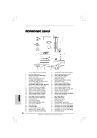
, White) 46 PCI Express 2.0 x1 Slot (PCIE3, White) 47 PCI Express 2.0 x16 Slot (PCIE2, Blue) 48 PCI Express 2.0 x1 Slot (PCIE1, White) 49 USB_PWR2 Jumper 2 ASRock P55 Extreme4 Motherboard English - ASRock P55 Extreme4 | Quick Installation Guide - Page 3
"Realtek HDA Primary output" to use Rear Speaker, Central/Bass, and Front Speaker, or select "Realtek HDA Audio 2nd output" to use front panel audio. 3 ASRock P55 Extreme4 Motherboard English - ASRock P55 Extreme4 | Quick Installation Guide - Page 4
Contents ASRock P55 Extreme4 Motherboard (ATX Form Factor: 12.0-in x 9.6-in, 30.5 cm x 24.4 cm) ASRock P55 Extreme4 Quick Installation Guide ASRock P55 Extreme4 Support CD 1 x 80-conductor Ultra ATA 66/100/133 IDE Ribbon Cable 1 x Ribbon Cable for a 3.5-in Floppy Drive 4 x Serial ATA (SATA) Data - ASRock P55 Extreme4 | Quick Installation Guide - Page 5
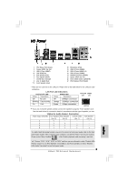
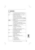
RTL8111E - Supports Wake-On-LAN - Supports LAN Cable Detection - Supports Energy Efficient Ethernet 802.3az I/O Panel - 1 x PS/2 Mouse Port - 1 x PS/2 Keyboard Port - 1 x Coaxial SPDIF Out Port - 1 x Optical SPDIF Out Port - 6 x Ready-to-Use USB 2.0 Ports 5 ASRock P55 Extreme4 Motherboard English - ASRock P55 Extreme4 | Quick Installation Guide - Page 6
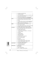
x USB 3.0 header (supports 2 USB 3.0 ports) - 1 x Dr. Debug (7-Segment Debug LED) - 1 x Clear CMOS Switch with LED - 1 x Power Switch with LED - 1 x Reset Switch with LED - 16Mb AMI BIOS - AMI Legal BIOS - Supports "Plug and Play" - ACPI 1.1 Compliance Wake Up Events ASRock P55 Extreme4 Motherboard - ASRock P55 Extreme4 | Quick Installation Guide - Page 7
overclocking tools. Overclocking may affect your system stability, or even cause damage to the components and devices of your system. It should be done at your own risk and expense. We are not responsible for possible damage caused by overclocking. English 7 ASRock P55 Extreme4 Motherboard - ASRock P55 Extreme4 | Quick Installation Guide - Page 8
the OC settings and share with others. It helps you to save your overclocking record under the operating system and simplifies the complicated recording process of overclocking settings. With OC DNA, you can save your OC settings as a profile and share with 8 ASRock P55 Extreme4 Motherboard English - ASRock P55 Extreme4 | Quick Installation Guide - Page 9
mode (S1), Suspend to RAM (S3), hibernation mode (S4) or power off (S5). With APP Charger driver installed, you can easily enjoy the marvelous charging experience than ever. ASRock website: http://www.asrock.com/Feature/AppCharger/index.asp 13. Although this motherboard offers stepless control, it - ASRock P55 Extreme4 | Quick Installation Guide - Page 10
Catalyst 9.12 Catalyst 9.12 Catalyst 9.12 Catalyst 9.12 Catalyst 9.12 * For the latest updates of the supported PCI Express VGA card list for CrossFireXTM Mode, please visit our website for details. ASRock website: http://www.asrock.com/support/index.htm English 10 ASRock P55 Extreme4 Motherboard - ASRock P55 Extreme4 | Quick Installation Guide - Page 11
you insert the 1156-Pin CPU into the socket, please check if the CPU surface is unclean or if there is any bent pin on the socket. Do not force to insert the CPU into the socket if above situation is found. Otherwise, the CPU will be seriously damaged. 11 ASRock P55 Extreme4 Motherboard English - ASRock P55 Extreme4 | Quick Installation Guide - Page 12
be placed if returning the motherboard for after service. Step 3. Insert the 1156-Pin CPU: Step 3-1. 1156-Pin Socket 1156-Pin CPU For proper inserting, please ensure to match the two orientation key notches of the CPU with the two alignment keys of the socket. 12 ASRock P55 Extreme4 Motherboard - ASRock P55 Extreme4 | Quick Installation Guide - Page 13
components. Please be noticed that this motherboard supports Combo Cooler Option (C.C.O.), which provides the flexible option to adopt two different CPU cooler types, Socket LGA 775 and LGA 1156. The white throughholes are for Socket LGA 1156 CPU fan. 13 ASRock P55 Extreme4 Motherboard English - ASRock P55 Extreme4 | Quick Installation Guide - Page 14
the Dual Channel Memory Technology. 3. It is not allowed to install a DDR or DDR2 memory module into DDR3 slot;otherwise, this motherboard and DIMM may be damaged. 4. Please install the memory module into the white slot (DDR3_B1) for the first priority. English 14 ASRock P55 Extreme4 Motherboard - ASRock P55 Extreme4 | Quick Installation Guide - Page 15
Installing a DIMM Please make sure to motherboard and the DIMM if you force the DIMM into the slot at incorrect orientation. Step 3. Firmly insert the DIMM into the slot until the retaining clips at both ends fully snap back in place and the DIMM is properly seated. 15 ASRock P55 Extreme4 Motherboard - ASRock P55 Extreme4 | Quick Installation Guide - Page 16
lane width graphics cards, or used to install PCI Express graphics cards to support CrossFireXTM or SLITM function. 1. In single VGA card mode, it is recommended to install a PCI Express x16 graphics card on with screws. Step 6. Replace the system cover. 16 ASRock P55 Extreme4 Motherboard English - ASRock P55 Extreme4 | Quick Installation Guide - Page 17
Guide This motherboard supports NVIDIA® SLITM and Quad SLITM (Scalable Link Interface) technology that allows you to install up to two identical PCI Express x16 graphics cards. Currently, NVIDIA® SLITM technology supports to the PCI Express graphics cards. 17 ASRock P55 Extreme4 Motherboard English - ASRock P55 Extreme4 | Quick Installation Guide - Page 18
ASRock SLI_Bridge_2S Card Step4. Connect a VGA cable or a DVI cable to the monitor connector or the DVI connector of the graphics card that is inserted to PCIE2 slot. 2.5.2 Driver Installation and Setup Install the graphics card drivers of SLITM feature. 18 ASRock P55 Extreme4 Motherboard English - ASRock P55 Extreme4 | Quick Installation Guide - Page 19
is a registered trademark of NVIDIA® Technologies Inc., and is used only for identification or explanation and to the owners' benefit, without intent to infringe. 19 ASRock P55 Extreme4 Motherboard English - ASRock P55 Extreme4 | Quick Installation Guide - Page 20
in the future, please refer to ATITM graphics card manuals for detailed installation guide. Step 1. Insert one Radeon graphics card into PCIE2 slot and the other Radeon graphics card to PCIE5 slot. Make sure that the cards are properly seated on the slots. 20 ASRock P55 Extreme4 Motherboard English - ASRock P55 Extreme4 | Quick Installation Guide - Page 21
, there is no need to download it again): http://www.microsoft.com/windowsxp/sp2/default.mspx B. You must have Microsoft .NET Framework installed prior to downloading and installing the CATALYST Control Center. Please check Microsoft website for details. 21 ASRock P55 Extreme4 Motherboard English - ASRock P55 Extreme4 | Quick Installation Guide - Page 22
Control Center. Please check AMD website for details. Restart your computer. Install the VGA card drivers to your system, and restart your computer. Then you will find " information of ATITM CrossFireXTM technology, please check AMD website for updates and details. 22 ASRock P55 Extreme4 Motherboard - ASRock P55 Extreme4 | Quick Installation Guide - Page 23
upgrade. With the external add-on PCI Express VGA cards, you can easily enjoy the benefits of Surround Display feature. For the detailed instruction, please refer to the document at the following path in the Support CD: ..\ Surround Display Information 23 ASRock P55 Extreme4 Motherboard English - ASRock P55 Extreme4 | Quick Installation Guide - Page 24
the system under S3 (Suspend to RAM) state. USB_PWR3 Short pin2, pin3 update the BIOS. If you need to clear the CMOS when you just finish updating the BIOS, you must boot up the system first, and then shut it down before you do the clear-CMOS action. English 24 ASRock P55 Extreme4 Motherboard - ASRock P55 Extreme4 | Quick Installation Guide - Page 25
(SATA3_3: see p.2, No. 11) (SATA3_4: see p.2, No. 10) SATA3_4 SATA3_3 SATA3_2 SATA3_1 These four Serial ATA3 (SATA3) connectors support SATA data cables for internal storage devices. The current SATA3 interface allows up to 6.0 Gb/s data transfer rate. English 25 ASRock P55 Extreme4 Motherboard - ASRock P55 Extreme4 | Quick Installation Guide - Page 26
support two USB 2.0 ports. (9-pin USB12_13) (see p.2 No. 35) USB 3.0 Header (19-pin USB3_2_3) (see p.2 No. 36) Besides two default USB 3.0 ports on the I/O panel, there is one USB 3.0 header on this motherboard. This USB 3.0 header can support two USB 3.0 ports. English 26 ASRock P55 Extreme4 - ASRock P55 Extreme4 | Quick Installation Guide - Page 27
on the chassis must support HDA to function correctly. Please follow the instruction in our manual and chassis manual to install your system. 2. If you use AC'97 audio panel, please install it to the front positive and negative pins before connecting the cables. 27 ASRock P55 Extreme4 Motherboard - ASRock P55 Extreme4 | Quick Installation Guide - Page 28
cables to the fan connectors and match the black wire to the ground pin. (3-pin CHA_FAN3) (see p.2 No. 12) (3-pin PWR_FAN1) (see p.2 No. 3) English 28 ASRock P55 Extreme4 Motherboard - ASRock P55 Extreme4 | Quick Installation Guide - Page 29
supply. To use the 4-pin ATX power supply, please plug your power supply along with Pin 1 and Pin 5. 8 5 4-Pin ATX 12V Power Supply Installation 4 1 Serial port Header (9-pin COM1) (see p.2 No.38) This COM1 header supports a serial port module. English 29 ASRock P55 Extreme4 Motherboard - ASRock P55 Extreme4 | Quick Installation Guide - Page 30
connector of HDMI VGA card to this header. Front USB 3.0 Panel This front USB 3.0 panel can support 2 additional USB 3.0 ports besides the I/O panel. Please connect the light blue connector on the cable of to page 24 "Clear CMOS jumper" description instead. 30 ASRock P55 Extreme4 Motherboard - ASRock P55 Extreme4 | Quick Installation Guide - Page 31
Uncompressed pointer for future use in PMM. Copying Main BIOS into memory. Leaves all RAM below 1MB Read-Write including E000 and F000 shadow areas but closing SMRAM. Restore CPUID value back into register. Give control to BIOS POST (ExecutePOSTKernel). English 31 ASRock P55 Extreme4 Motherboard - ASRock P55 Extreme4 | Quick Installation Guide - Page 32
adapter installed in the system that have optional ROMs. Initializes all the output devices. Allocate memory for ADM module and uncompress it. Give control to ADM module for initialization. Initialize language and font modules for ADM. Activate ADM module. ASRock P55 Extreme4 Motherboard English - ASRock P55 Extreme4 | Quick Installation Guide - Page 33
implementation that needs an adjustment in system RAM size if needed. 52 Updates CMOS memory size from memory found in memory test. Allocates memory for Extended BIOS Data Area from base memory. 60 00 Passes control to OS Loader (typically INT19h). English 33 ASRock P55 Extreme4 Motherboard - ASRock P55 Extreme4 | Quick Installation Guide - Page 34
steps. Using SATA / SATAII HDDs without NCQ function STEP 1: Set up BIOS. A. Enter BIOS SETUP UTILITY Advanced screen Storage Configuration. B. Set the option "SATAII Operation Mode" to [IDE]. STEP 2: Install Windows® XP / XP 64-bit OS on your system. 34 ASRock P55 Extreme4 Motherboard English - ASRock P55 Extreme4 | Quick Installation Guide - Page 35
during overclocking, but PCI / PCIE buses are in the fixed mode so that FSB can operate under a more stable overclocking environment. Please refer to the warning on page 7 for the possible overclocking risk before you apply Untied Overclocking Technology. 35 ASRock P55 Extreme4 Motherboard English - ASRock P55 Extreme4 | Quick Installation Guide - Page 36
detailed information about BIOS Setup, please refer to the User Manual (PDF file) contained in the Support CD. 4. Software Support CD information This motherboard supports various Microsoft® EXE" from the BIN folder in the Support CD to display the menus. 36 ASRock P55 Extreme4 Motherboard English - ASRock P55 Extreme4 | Quick Installation Guide - Page 37
P55 Extreme4 Motherboard (ATX-Formfaktor: 30.5 cm x 24.4 cm; 12.0 Zoll x 9.6 Zoll) ASRock P55 Extreme4 Schnellinstallationsanleitung ASRock P55 Extreme4 Support-CD Ein 80-adriges Ultra-ATA 66/100/133 IDE-Flachbandkabel Ein Flachbandkabel für ein 3,5-Zoll-Diskettenlaufwerk Vier Serial ATA (SATA - ASRock P55 Extreme4 | Quick Installation Guide - Page 38
ATX-Formfaktor: 30.5 cm x 24.4 cm; 12.0 Zoll x 9.6 Zoll - Alle Feste Kondensatordesign (100% in Japan gefertigte, erstklassige leitfähige Polymer-Kondensatoren) - Unterstützt Intel® CoreTM i7 / i5 / i3 und Pentium® G6950- Prozessoren im LGA1156 ASRock P55 Extreme4 Motherboard Deutsch - ASRock P55 Extreme4 | Quick Installation Guide - Page 39
6 x Serial ATAII 3,0 GB/s-Anschlüsse, unterstützen RAID(RAID 0, RAID 1, RAID 10, RAID 5 und Intel Rapid Storage), NCQ, AHCI und "Hot Plug" Funktionen - 4 x SATA3 6,0 GB/s-Anschlüsse - 1 x ATA133 IDE-Anschl üsse) - 1 x Dr. Debug (Debug-LED mit 7 Segmenten) 39 ASRock P55 Extreme4 Motherboard Deutsch - ASRock P55 Extreme4 | Quick Installation Guide - Page 40
: +12V, +5V, +3.3V, Vcore Betriebssysteme - Unterstützt Microsoft® Windows® 7 / 7 64-Bit / VistaTM / VistaTM 64-Bit / XP / XP 64-Bit Zertifizierungen - FCC, CE, WHQL Deutsch 40 ASRock P55 Extreme4 Motherboard - ASRock P55 Extreme4 | Quick Installation Guide - Page 41
asrock.com WARNUNG Beachten Sie bitte, dass Overclocking, einschließlich der Einstellung im BIOS, Anwenden der Untied Overclocking-Technologie oder Verwenden von Overclocking von ASRock OC Tuner. ASRock-Website: http://www.asrock.com/feature/OCTuner/index.htm 41 ASRock P55 Extreme4 Motherboard - ASRock P55 Extreme4 | Quick Installation Guide - Page 42
Drücken der -Taste im BIOS-Setup-Menü Zugang zu ASRock Instant Flash. Sie brauchen dieses Werkzeug einfach nur zu starten und die neue BIOS-Datei auf Ihrem USB-Flash-Laufwerk, erdem daran, regelmäßig einen Blick auf die offizielle ASRock- 42 ASRock P55 Extreme4 Motherboard Deutsch - ASRock P55 Extreme4 | Quick Installation Guide - Page 43
hleroption bietet die flexible Möglichkeit zur Aufnahme von zwei verschiedenen CPU-Kühlertypen, Socket LGA 775 und LGA 1156. Beachten Sie bitte, dass nicht alle 775 CPU-Lüfter verwendet werden kö Details beim Hersteller der Stromversorgung abzufragen. 43 ASRock P55 Extreme4 Motherboard Deutsch - ASRock P55 Extreme4 | Quick Installation Guide - Page 44
) 1156-Pin Sockel Übersicht Bevor Sie die 1156-Pin CPU in den Sockel sitzen, prüfen Sie bitte, ob die CPU-Oberfläche sauber ist und keine der Kontakte verbogen sind. Setzen Sie die CPU nicht mit Gewalt in den Sockel, dies kann die CPU schwer beschädigen. Deutsch 44 ASRock P55 Extreme4 Motherboard - ASRock P55 Extreme4 | Quick Installation Guide - Page 45
dem IHS (Integrated Heat Sink - integrierter Kühlkörper) nach oben. Suchen Sie Pin 1 und die zwei Orientierungseinkerbungen. Orientierungskerbe Ausrichtungsmarkierung Pin1 Orientierungskerbe 1156-Pin CPU Ausrichtungsmarkierung 1156-Pin Sockel ASRock P55 Extreme4 Motherboard Pin1 45 Deutsch - ASRock P55 Extreme4 | Quick Installation Guide - Page 46
(IHS). Schritt 4-2. Drücken Sie leicht auf die Ladeplatte und schließen Sie den Ladehebel. Schritt 4-3. Sichern Sie Ladehebel und Ladeplatte mithilfe des Hebelverschlusses. 46 ASRock P55 Extreme4 Motherboard Deutsch - ASRock P55 Extreme4 | Quick Installation Guide - Page 47
dieses Motherboard die ComboKühleroption unterstützt, die eine flexible Möglichkeit zur Aufnahme von zwei verschiedenen CPU-Kühlertypen, Socket LGA 775 und LGA 1156, bietet. Das weiße Durchgangsloch ist für den CPULüfter im Socket LGA 1156 vorgesehen. 47 ASRock P55 Extreme4 Motherboard Deutsch - ASRock P55 Extreme4 | Quick Installation Guide - Page 48
2.3 Installation der Speichermodule (DIMM) Die Motherboards P55 Extreme4 bieten vier 240-pol. DDR3 (Double Data Rate Motherboard und DIMMs beschädigt werden. 4. Installieren Sie das Speichermodul für die erste Priorität im weißen Steckplatz (DDR3_B1). Deutsch 48 ASRock P55 Extreme4 Motherboard - ASRock P55 Extreme4 | Quick Installation Guide - Page 49
in die Steckplätze, so dass die Halteklammern an beiden Enden des Moduls einschnappen und das DIMM-Modul fest an Ort und Stelle sitzt. 49 ASRock P55 Extreme4 Motherboard - ASRock P55 Extreme4 | Quick Installation Guide - Page 50
einen 2 PCI-Steckplätze und 5 PCI Express-Steckplätze am P55 Extreme4 Motherboard. PCI-Slots: PCI-Slots werden zur Installation von Erweiterungskarten mit dem 32bit PCI-Interface genutzt. PCI Express-Slots: PCIE1 die Karte mit der Schraube aus Schritt 2. Deutsch 50 ASRock P55 Extreme4 Motherboard - ASRock P55 Extreme4 | Quick Installation Guide - Page 51
von den Betriebssystemen Windows® XP mit Service Pack 2 / VistaTM / 7 unterst Updates gibt. Beachten Sie den detailliert erklärten Installationsablauf auf Seite 20. 2.7 "Surround Display" Dieses Motherboard Support-CD: ..\ Surround Display Information 51 ASRock P55 Extreme4 Motherboard Deutsch - ASRock P55 Extreme4 | Quick Installation Guide - Page 52
+5V_DUAL auswahlen, konnen USB-Gerate das System aus dem S3-Zustand (Suspend to RAM) aufwecken. USB_PWR3 Überbrücken Sie Pin2, Pin3, um (siehe S.2, No. Passwort, Datum, Zeit und die verschiedenen BIOS-Parameter. Um die Systemparameter zu löschen und auf die 52 ASRock P55 Extreme4 Motherboard - ASRock P55 Extreme4 | Quick Installation Guide - Page 53
Wenn Sie den CMOSInhalt gleich nach dem Aktualisieren des BIOS löschen müssen, müssen Sie zuerst das System SATA-Datenkabel SATAII_1 für interne Massenspeichergeräte. Die aktuelle SATAII-Schnittstelle SATAII_2 ermöglicht eine Datenübertragungsrate bis 3,0 Gb/s. 53 ASRock P55 Extreme4 Motherboard - ASRock P55 Extreme4 | Quick Installation Guide - Page 54
siehe S.2 - No. 34) Zusätzlich zu den sechs üblichen USB 2.0-Ports an den I/O-Anschlüssen befinden sich drei USB 2.0Anschlussleisten am Motherboard. Pro USB 2.0Anschlussleiste werden zwei USB 2.0-Ports unterstützt. (9-pol. USB12_13) (siehe S.2 - No. 35) Deutsch 54 ASRock P55 Extreme4 Motherboard - ASRock P55 Extreme4 | Quick Installation Guide - Page 55
Gehäuse HDA unterstützen muss, um richtig zu funktionieren. Beachten Sie bei der Installation im System die Anweisungen in unserem Handbuch und im Gehäusehandbuch. 2. Wenn Sie die angeschlossen werden. E. So aktivieren Sie das Mikrofon an der Vorderseite. 55 ASRock P55 Extreme4 Motherboard Deutsch - ASRock P55 Extreme4 | Quick Installation Guide - Page 56
die Kabel- und Pinbelegung korrekt übereinstimmen. Gehäuselautsprecher-Header (4-pin SPEAKER1) (siehe S.2 - No. 29) Schließen Sie den Gehäuselautsprecher an diesen Header an. 56 ASRock P55 Extreme4 Motherboard Deutsch - ASRock P55 Extreme4 | Quick Installation Guide - Page 57
ßen möchten, verbinden Sie ihn bitte mit den Pins 1 - 3. Pins 1-3 anschließen Lüfter mit dreipoligem Anschluss installieren ATX-Netz-Header (24-pin ATXPWR1) (siehe S.2 - No. 9) 12 24 1 13 Verbinden Sie die ATXStromversorgung mit diesem Header. Deutsch 57 ASRock P55 Extreme4 Motherboard - ASRock P55 Extreme4 | Quick Installation Guide - Page 58
Sie bitte Ihre Energieversorgung zusammen mit dem Pin 1 und Pin 5 ein. 8 5 Installation der 4-Pin ATX 12V Energieversorgung 4 1 COM-Anschluss-Header (9-pin COM1) (siehe S.2 - No. 38 den HDMI_SPDIF-Anschluss der HDMI-VGA-Karte mit diesem Anschluss. Deutsch 58 ASRock P55 Extreme4 Motherboard - ASRock P55 Extreme4 | Quick Installation Guide - Page 59
Kabels dieser USB 3.0Grondblende am USB 3.0Header (USB3_2_3) an und befestigen Sie die USB 3.0Frontblende mit den sechs mitgelieferten Schrauben am Gehäuse. Deutsch 59 ASRock P55 Extreme4 Motherboard - ASRock P55 Extreme4 | Quick Installation Guide - Page 60
2.10 Schnellschalter Dieses Motherboard besitzt drei Schnellschalter: Netzschalter, Rücksetzschalter (Reset) und CMOS löschen-Schalter, mit denen Benutzer das System auf die Beschreibung "Clear CMOS jumper" (CMOS löschen-Jumper) auf Seite 53 beziehen. Deutsch 60 ASRock P55 Extreme4 Motherboard - ASRock P55 Extreme4 | Quick Installation Guide - Page 61
1: BIOS einrichten. A. Rufen Sie das BIOS SETUP UTILITY auf, wählen Sie den „Advanced"- Bildschirm (Erweitert), dann „Storage Configuration". B. Stellen Sie "SATAII Operation Mode" auf [IDE]. SCHRITT 2: Installieren Sie Windows® XP / XP 64-Bit in Ihrem System. 61 ASRock P55 Extreme4 Motherboard - ASRock P55 Extreme4 | Quick Installation Guide - Page 62
das BIOS SETUP UTILITY auf, wählen Sie den „Advanced"- Bildschirm (Erweitert), dann „Storage Configuration". B. Stellen Sie "SATAII Operation Mode" auf [AHCI]. SCHRITT 2: Installieren Sie Windows® 7 / 7 64-Bit / VistaTM / VistaTM 64-Bit in Ihrem System. 62 ASRock P55 Extreme4 Motherboard Deutsch - ASRock P55 Extreme4 | Quick Installation Guide - Page 63
der Support-CD, um die Menüs aufzurufen. Das Setup-Programm soll es Ihnen so leicht wie möglich machen. Es ist menügesteuert, d.h. Sie können in den verschiedenen Untermenüs Ihre Auswahl treffen und die Programme werden dann automatisch installiert. 63 ASRock P55 Extreme4 Motherboard Deutsch - ASRock P55 Extreme4 | Quick Installation Guide - Page 64
res au modèle que vous utilisez. www.asrock.com/support/index.asp 1.1 Contenu du paquet Carte mère ASRock P55 Extreme4 (Facteur de forme ATX: 12.0 pouces x 9.6 pouces, 30.5 cm x 24.4 cm) Guide d'installation rapide ASRock P55 Extreme4 CD de soutien ASRock P55 Extreme4 Un câble ruban IDE Ultra ATA 66 - ASRock P55 Extreme4 | Quick Installation Guide - Page 65
charge THX TruStudio ProTM - PCIE x1 Gigabit LAN 10/100/1000 Mb/s - Realtek RTL8111E - Support du Wake-On-LAN - Prise en charge de la détection de câble LAN - Prend en charge la norme Energy Efficient Ethernet (Ethernet à efficacité énergétique) 802.3az 65 ASRock P55 Extreme4 Motherboard Français - ASRock P55 Extreme4 | Quick Installation Guide - Page 66
0Go/s, supporte RAID (RAID 0, RAID 1,RAID 10, RAID 5 et mémoire à sélection rapid), NCQ, AHCI et "Hot-Plug" (Connexion à chaud) - 4 x connecteurs SATA3, processeur/châssis/ventilateur - br. 24 connecteur d'alimentation ATX - br. 8 connecteur d'alimentation 12V ATX ASRock P55 Extreme4 Motherboard - ASRock P55 Extreme4 | Quick Installation Guide - Page 67
BIOS AMI - BIOS AMI - Support du "Plug and Play" - Compatible pour événements de réveil ACPI 1.1 - Gestion jumperless - Support SMBIOS 2.3.1 - CPU, DRAM, VTT, PCH, CPU PLL Tension Multi-ajustement - Supporter I. O. T. (Technologie d'Overclocking 3V, Vcore 67 ASRock P55 Extreme4 Motherboard Français - ASRock P55 Extreme4 | Quick Installation Guide - Page 68
obtenir les meilleures performances du système sous environnement Windows®. S'il vous plaît visitez notre site web pour le fonctionnement des procédures de Tuner ASRock OC. ASRock website: http://www.asrock.com/feature/OCTuner/index.htm Français 68 ASRock P55 Extreme4 Motherboard - ASRock P55 Extreme4 | Quick Installation Guide - Page 69
suffit simplement d'installer l'utilitaire ASRock AIWI à partir du site web officiel ASRock ou du CD logiciels ASRock sur votre ASRock, nous fournissons en permanence les derniers jeux compatibles ! Site web ASRock : http://www.asrock.com/Feature/Aiwi/index.asp 69 ASRock P55 Extreme4 Motherboard - ASRock P55 Extreme4 | Quick Installation Guide - Page 70
installation du PC. 15. Le Combo Cooler Option (C.C.O.) offre un choix flexible pour adopter deux types différents de refroidisseur sde CPU, les sockets LGA 775 et LGA 1156 sont requises. Selon les suggestions d'Intel', l'alimentation électrique EuP doit ASRock P55 Extreme4 Motherboard Français - ASRock P55 Extreme4 | Quick Installation Guide - Page 71
dans le socket, veuillez vérifier que la surface du processeur est bien propre, et qu'il n'y a aucune broche tordue sur le socket. Si c'est le cas, ne forcez pas pour insérer le processeur dans le socket. Sinon, le processeur sera gravement endommagé. Français 71 ASRock P55 Extreme4 Motherboard - ASRock P55 Extreme4 | Quick Installation Guide - Page 72
mis en place si vous renvoyez la carte mère pour service après vente. Etape 3. Insérez le processeur 1156 broches : Etape 3-1. Tenez le processeur par ses bords là trompeur broche 1 Détrompeur Encoche d'orientation Socket 1156 broches 72 Processeur 1156 broches ASRock P55 Extreme4 Motherboard - ASRock P55 Extreme4 | Quick Installation Guide - Page 73
. L'exemple ci-dessous illustre l'installation du dissipateur thermique pour un processeur 1366 broches. (Appliquez le matériau d'interface thermique) Etape 1. Appliquez le matériau d'interface thermique au centre de IHS sur la surface du socket. Français 73 ASRock P55 Extreme4 Motherboard - ASRock P55 Extreme4 | Quick Installation Guide - Page 74
, puis, du pouce, enfoncez les capuchons des attaches pour les installer et les verrouiller. Répétez l'opération avec les autres attaches. sockets LGA 775 et LGA 1156. Les trous traversant blancs sont pour le ventilateur de CPU au socket LGA 1156. Français 74 ASRock P55 Extreme4 Motherboard - ASRock P55 Extreme4 | Quick Installation Guide - Page 75
Technologie de Mémoire à Canal Double. 3. Il n'est pas permis d'installer de la DDR ou DDR2 sur le slot DDR3; la carte mère et les DIMM pourraient être endommagés. 4. Veuillez tout d'abord installer le module de mémoire dans la fente blanche (DDR3_B1). Français 75 ASRock P55 Extreme4 Motherboard - ASRock P55 Extreme4 | Quick Installation Guide - Page 76
Installation d'un module DIMM Ayez bien le soin de débrancher l'alimentation avant d'ajouter ou de retirer des modules DIMM ou les composants du clips de maintien situés aux deux extrémités se ferment complètement et que le module DIMM soit inséré correctement. 76 ASRock P55 Extreme4 Motherboard - ASRock P55 Extreme4 | Quick Installation Guide - Page 77
Express) Il y a 2 ports PCI et 5 ports PCI Express sur la carte mère P55 Extreme4. Slots PCI: Les slots PCI sont utilisés pour installer des cartes d'extension dotées d'une interface PCI 32 bits. Slots PCIE: Le PCIE1 / sur le châssis à l'aide d'une vis. Français 77 ASRock P55 Extreme4 Motherboard - ASRock P55 Extreme4 | Quick Installation Guide - Page 78
, vous pouvez facilement jouir des avantages de la caractéristique de l'affichage Surround. Pour les instructions détaillées, veuillez vous reporter au document qui se trouve sur le chemin suivant dans le CD d'assistance : ..\ Surround Display Information 78 ASRock P55 Extreme4 Motherboard Français - ASRock P55 Extreme4 | Quick Installation Guide - Page 79
vous selectionnez +5V_DUAL, les peripheriques USB reveillent le systeme en etat S3 (Suspension a la RAM). USB_PWR3 Court-circuitez les broches 2 (voir p.2 fig. 31) et 3 pour choisir + Amp et un courant standby supérieur fourni par l'alimentation. Français 79 ASRock P55 Extreme4 Motherboard - ASRock P55 Extreme4 | Quick Installation Guide - Page 80
suite après avoir mis le BIOS à jour. Si vous avez besoin d'effacer la CMOS lorsque vous avez fini de mettre le BIOS à jour, vous devez d'abord initialiser le système, puis le mettre hors tension avant de procéder à l'opération d'effacement de la CMOS. Français 80 ASRock P55 Extreme4 Motherboard - ASRock P55 Extreme4 | Quick Installation Guide - Page 81
aux instructions du fabricant SATA3) prennent en charge les câbles SATA pour les périphériques de stockage (SATA3_4: voir p.2 No. 10) SATA3_2 internes. L'interface SATA3 SATA3_1 actuelle permet des taux transferts de données pouvant aller jusqu'à 6,0 Gb/s. 81 ASRock P55 Extreme4 Motherboard - ASRock P55 Extreme4 | Quick Installation Guide - Page 82
(voir p.2 No. 34) Toute cote du cable de data SATA peut etre connecte au disque dur SATA / SATAII / SATA3 ou au connecteur SATAII / SATA3 sur la carte mere. Veuillez connecter l'extrémité noire du . Cette barrette USB 3.0 peut prendre en charge deux ports USB 3.0. 82 ASRock P55 Extreme4 Motherboard - ASRock P55 Extreme4 | Quick Installation Guide - Page 83
(HD_AUDIO1 br. 9) (voir p.2 No. 40) CD1 Cet en-tête supporte un module infrarouge optionnel de transfert et de réception sans fil. Ils vous correctement. Veuillez suivre les instructions dans notre manuel et le manuel de châssis afin installer votre système. 2. Si ASRock P55 Extreme4 Motherboard - ASRock P55 Extreme4 | Quick Installation Guide - Page 84
(CHA_FAN1 br. 4) (voir p.2 No. 25) ventilateur aux connecteurs pour ventilateur et faites correspondre (CHA_FAN2 br. 3) (voir p.2 No. 8) le fil noir à la broche de terre. 84 ASRock P55 Extreme4 Motherboard - ASRock P55 Extreme4 | Quick Installation Guide - Page 85
carte mère offre un support de (Ventilateur silencieux) ventilateur ATX 12V alimentation. Pour utiliser l'alimentation des 4 broches ATX, branchez votre alimentation avec la broche 1 et la broche 5. 8 5 4-Installation d'alimentation à 4 broches ATX 12V 4 1 85 ASRock P55 Extreme4 Motherboard - ASRock P55 Extreme4 | Quick Installation Guide - Page 86
panneau avant USB 3.0 sur la barrette USB 3.0 (USB3_2_3) et fixez le panneau avant USB 3.0 au châssis à l'aide des six vis fournies. Français 86 ASRock P55 Extreme4 Motherboard - ASRock P55 Extreme4 | Quick Installation Guide - Page 87
passe de votre système ou vous référer plutôt à la description "Clear CMOS jumper (Cavalier d'effacement du CMOS)" de la page 80. Français 87 ASRock P55 Extreme4 Motherboard - ASRock P55 Extreme4 | Quick Installation Guide - Page 88
Configurez le BIOS. A. Accédez à BIOS SETUP UTILITY (Utilitaire de configuration BIOS) écran Avancé Configuration Storage. B. Réglez «SATAII Operation Mode « sur [IDE]. ETAPE 2 : Installez le système d'exploitation Windows® XP / XP 64 bits sur votre système. 88 ASRock P55 Extreme4 Motherboard Fran - ASRock P55 Extreme4 | Quick Installation Guide - Page 89
dez à BIOS SETUP UTILITY (Utilitaire de configuration BIOS) écran Avancé Configuration Storage. B. Réglez «SATAII Operation Mode « sur [AHCI]. ETAPE 2: Installer le système d'exploitation Windows® 7 / 7 64-bit / VistaTM / VistaTM 64-bit sur votre système. 89 ASRock P55 Extreme4 Motherboard Français - ASRock P55 Extreme4 | Quick Installation Guide - Page 90
le système et en le rallumant. L'utilitaire d'installation du BIOS est conçu pour être convivial. C'est un BIOS, veuillez consulter le Guide de l'utilisateur (fichier PDF) dans le CD technique. 4. Informations sur le CD de support Cette carte mère supporte ASRock P55 Extreme4 Motherboard Français - ASRock P55 Extreme4 | Quick Installation Guide - Page 91
sul modello che si sta usando. www.asrock.com/support/index.asp 1.1 Contenuto della confezione Scheda madre ASRock P55 Extreme4 (ATX Form Factor: 12.0-in x 9.6-in, 30.5 cm x 24.4 cm) Guida di installazione rapida ASRock P55 Extreme4 CD di supporto ASRock P55 Extreme4 Un cavo IDE 80-pin Ultra ATA 66 - ASRock P55 Extreme4 | Quick Installation Guide - Page 92
- Supporta il rilevamento cavo LAN - Supporto di Energy Efficient Ethernet 802.3az I/O Panel - 1 x porta PS/2 per mouse - 1 x porta PS/2 per tastiera - 1 x Porta coassiale SPDIF Out ASRock P55 Extreme4 Motherboard Italiano - ASRock P55 Extreme4 | Quick Installation Guide - Page 93
RAID (RAID 0, RAID 1, RAID 10, RAID 5 ed Intel Rapid Storage), NCQ, AHCI e "Collegamento a caldo" - 4 x connettori SATA3 ventola - 24-pin collettore alimentazione ATX - 8-pin connettore ATX 12V - Connettori audio interni di reset con LED - 16Mb AMI BIOS 93 ASRock P55 Extreme4 Motherboard Italiano - ASRock P55 Extreme4 | Quick Installation Guide - Page 94
- Predisposto ErP/EuP (è necessaria l'alimentazione predisposta per il sistema ErP/EuP) (vedi ATTENZIONE 16) * Per ulteriori informazioni, prego visitare il nostro sito internet: http://www.asrock.com Italiano 94 ASRock P55 Extreme4 Motherboard - ASRock P55 Extreme4 | Quick Installation Guide - Page 95
strumento d'aggiornamento del BIOS permette di aggiornare il sistema BIOS senza accedere a sistemi operativi come MSDOS or Windows®. Con questa utilità, si può premere il tasto durante il POST, oppure il tasto nel menu BIOS per accedere ad 95 ASRock P55 Extreme4 Motherboard Italiano - ASRock P55 Extreme4 | Quick Installation Guide - Page 96
alla modalità di Standby (S1), Sospensione su RAM (S3), Ibernazione (S4) o Spegnimento (S5). Una volta installato il driver APP Charger si otterranno prodigi e comodità mai avuti prima. Sito ASRock: http://www.asrock.com/Feature/AppCharger/index.asp 96 ASRock P55 Extreme4 Motherboard Italiano - ASRock P55 Extreme4 | Quick Installation Guide - Page 97
motherboard offre il controllo stepless, non si consiglia di effettuare l'overclocking di dispersori di calore CPU, Socket LGA 775 e LGA 1156. Notare che non possono essere EuP. In base ai suggerimenti Intel l'alimentatore predisposto EuP deve soddisfare lo ASRock P55 Extreme4 Motherboard Italiano - ASRock P55 Extreme4 | Quick Installation Guide - Page 98
la CPU da 1156-Pin nel socket, verificare che la superficie della CPU sia pulita e che non ci siano pin piegati nel socket. Non forzare l'inserimento della CPU nel socket se ci sono pin piegati. In caso contrario la CPU potrebbe essere seriamente danneggiata. 98 ASRock P55 Extreme4 Motherboard - ASRock P55 Extreme4 | Quick Installation Guide - Page 99
madre deve essere restituita per l'assistenza. Linea nera Fase 3. Inserire la CPU 1156-Pin: Fase 3-1. Tenere la CPU dai bordi segnati con linee nere. Fase Pin1 Dente di orientamento CPU da 1156-Pin Tacca di allineamento Socket da 1156-Pin ASRock P55 Extreme4 Motherboard Pin1 99 Italiano - ASRock P55 Extreme4 | Quick Installation Guide - Page 100
, verificare di far combaciare i due denti di allineamento della CPU con le due tacche nel socket. Fase 3-3. Collocare con delicatezza la CPU sulla presa con un movimento puramente verticale. Fase 3-4. linguetta di ritenzione della leva di carico. Italiano 100 ASRock P55 Extreme4 Motherboard - ASRock P55 Extreme4 | Quick Installation Guide - Page 101
che questa scheda mare supporta l'opzione C.C.O. (Combo Cooler Option), che fornisce la flessibilità di impiegare due tipi diversi di dispersori di calore CPU, Socket LGA 775 e LGA 1156. I fori di colore bianco sono per la ventola CPU Socket LGA 1156. ASRock P55 Extreme4 Motherboard 101 Italiano - ASRock P55 Extreme4 | Quick Installation Guide - Page 102
2.3 Installazione dei moduli di memoria (DIMM) La scheda madre P55 Extreme4 fornisce quattro alloggiamenti DIMM DDR3 (Double Data Rate 3) a 240 pin, e supporta la tecnologia Dual il modulo di memoria nell'alloggio bianco (DDR3_B1) per la prima priorità. Italiano 102 ASRock P55 Extreme4 Motherboard - ASRock P55 Extreme4 | Quick Installation Guide - Page 103
la DIMM nello slot fino a far scattare completamente in posizione i fermagli di ritegno alle due estremità e fino ad installare correttamente la DIMM nella sua sede. ASRock P55 Extreme4 Motherboard 103 - ASRock P55 Extreme4 | Quick Installation Guide - Page 104
2.4 Slot di espansione (Slot PCI ed Slot PCI Express) Sulla scheda madre P55 Extreme4 c'è 2 slot PCI ed 5 slot PCI Express. Slot PCI: Sono utilizzati per installare schede di inserita nello slot. Step 4. Agganciare la scheda allo chassis con le viti. Italiano 104 ASRock P55 Extreme4 Motherboard - ASRock P55 Extreme4 | Quick Installation Guide - Page 105
è supportata solo dai sistemi operativi Windows® XP con Service Pack 2 / VistaTM / 7. La funzione Quad CrossFireXTM Visitare il sito AMD per gli aggiornamenti dei driver ATITM CrossFireXTM. Attenersi alle procedure d'installazione, a Information Italiano ASRock P55 Extreme4 Motherboard 105 - ASRock P55 Extreme4 | Quick Installation Guide - Page 106
) e abilitare USB8_9/10_11/12_13 wake up events. Nota: Per selezionare +5VSB, si richiedono almeno 2 Ampere e il consumo di corrente in standby sarà maggiore. Italiano 106 ASRock P55 Extreme4 Motherboard - ASRock P55 Extreme4 | Quick Installation Guide - Page 107
. Non cancellare la CMOS subito dopo aver aggiornato il BIOS. Se è necessario cancellare la CMOS una volta completato l'aggiornamento del BIOS, è necessario riavviare prima il sistema, e poi spegnerlo prima di procedere alla cancellazione della CMOS. Italiano ASRock P55 Extreme4 Motherboard 107 - ASRock P55 Extreme4 | Quick Installation Guide - Page 108
SATA3_2 SATA3_1 Questi quattro connettori Serial ATA3 (SATA3) supportano cavi dati SATA per dispositivi di immagazzinamento interni. ATA3 (SATA3) supportano cavi SATA per dispositivi di memoria interni. L'interfaccia SATA3 attuale permette velocità di 108 ASRock P55 Extreme4 Motherboard Italiano - ASRock P55 Extreme4 | Quick Installation Guide - Page 109
Gb/s. Una o altra estremità del cavo di dati SATA può essere collegata al disco rigido SATA / SATAII / SATA3 o al connettore di SATAII / SATA3 su questa cartolina base. Collegare l'estremità nera de di un header USB 3.0 che supporta due porte USB 3.0. Italiano ASRock P55 Extreme4 Motherboard 109 - ASRock P55 Extreme4 | Quick Installation Guide - Page 110
far sì che questa operi in modo corretto. Attenersi alle istruzioni del nostro manuale e del manuale del telaio per installare il sistema. 2. Se si utilizza un pannello audio ) Questo collettore accomoda diverse funzioni di sistema pannello frontale. Italiano 110 ASRock P55 Extreme4 Motherboard - ASRock P55 Extreme4 | Quick Installation Guide - Page 111
Collegare i cavi della ventola ai (4-pin CHA_FAN1) corrispondenti connettori (vedi p.2 Nr. 25) facendo combaciare il cavo nero col pin di terra. (3-pin CHA_FAN2) (vedi p.2 Nr. 8) ASRock P55 Extreme4 Motherboard 111 - ASRock P55 Extreme4 | Quick Installation Guide - Page 112
essere funzionante se viene utilizzata una fornitura elettrica tradizionale a 4-pin ATX 12V. Per usare tale fornitura elettrica 4-pin ATX 12V, prego collegare la presa elettrica al Pin 1 e Pin 5. 8 5 Installazione elettrica 4-Pin ATX 12V 4 1 Italiano 112 ASRock P55 Extreme4 Motherboard - ASRock P55 Extreme4 | Quick Installation Guide - Page 113
cavo di questo pannello frontale USB 3.0 all'header USB 3.0 (USB3_2_3) e fissare il pannello frontale USB 3.0 al telaio usando le sei viti fornite in dotazione. Italiano ASRock P55 Extreme4 Motherboard 113 - ASRock P55 Extreme4 | Quick Installation Guide - Page 114
CMOS, prima è necessario annullare la password di sistema, oppure fare riferimento alla descrizione della sezione "Jumper Clear CMOS" (Jumper cancella CMOS) a pagina 107. Italiano 114 ASRock P55 Extreme4 Motherboard - ASRock P55 Extreme4 | Quick Installation Guide - Page 115
Configurare il BIOS. A. Entrare in BIOS SETUP UTILITY (UTILITÀ DI CONFIGURAZIONE DEL BIOS) Advanced screen (Avanzate) Storage Configuration. B. Impostare "SATAII Operation Mode" su [IDE]. Passo 2: Installazione di Windows® XP / XP 64-bit sul sistema. Italiano ASRock P55 Extreme4 Motherboard 115 - ASRock P55 Extreme4 | Quick Installation Guide - Page 116
Entrare in BIOS SETUP UTILITY (UTILITÀ DI CONFIGURAZIONE DEL BIOS) Advanced screen (Avanzate) Storage Configuration. B. Impostare "SATAII Operation Mode" su [AHCI]. Passo 2: Installazione di Windows® 7 / 7 64-bit / VistaTM / VistaTM 64-bit sul sistema. Italiano 116 ASRock P55 Extreme4 Motherboard - ASRock P55 Extreme4 | Quick Installation Guide - Page 117
informazioni più dettagliate circa il Setup del BIOS, fare riferimento al Manuale dell'Utente (PDF file) contenuto nel cd Il CD di supporto a corredo della scheda madre contiene i driver e utilità necessari a potenziare le caratteristiche della scheda. Inserire il ASRock P55 Extreme4 Motherboard 117 - ASRock P55 Extreme4 | Quick Installation Guide - Page 118
modelo específico de su placa. www.asrock.com/support/index.asp 1.1 Contenido de la caja Placa base ASRock P55 Extreme4 (Factor forma ATX: 30,5 cm x 24,4 cm, 12,0" x 9,6") Guía de instalación rápida de ASRock P55 Extreme4 CD de soporte de ASRock P55 Extreme4 Una cinta de datos IDE de conducción 80 - ASRock P55 Extreme4 | Quick Installation Guide - Page 119
ATX: 30,5 cm x 24,4 cm, 12,0" x 9,6" - Todo diseño de Capacitor Sólido (condensadores de polímero conductor de alta calidad 100% fabricados en Japón) - Admite los procesadores Intel® CoreTM i7 / i5 / i3 y Pentium® G6950 con encapsulado LGA1156 SPDIF ASRock P55 Extreme4 Motherboard 119 Español - ASRock P55 Extreme4 | Quick Installation Guide - Page 120
de ATX 12V power - Conector de Audio Interno - Conector de audio de panel frontal - 3 x Cabezal USB 2.0 (admite 6 puertos USB 2.0 adicionales) - 1 x Cabezal USB 3.0 (admite 2 puertos USB 3.0 adicionales) - 1 x Dr. Debug (indicador LED de avería de 7 segmentos) ASRock P55 Extreme4 Motherboard - ASRock P55 Extreme4 | Quick Installation Guide - Page 121
BIOS - Soporta "Plug and Play" - ACPI 1.1 compliance wake up events - Soporta "jumper free" - Soporta SMBIOS 2.3.1 - Múltiple ajuste de CPU, DRAM, VTT, PCH, CPU PLL Voltage - Apoya I.O.T. (Tecnología Inteligente de Overclocking : +12V, +5V, +3.3V, Vcore Español ASRock P55 Extreme4 Motherboard 121 - ASRock P55 Extreme4 | Quick Installation Guide - Page 122
incluido el ajuste del BIOS, aplicando la tecnología de favor consulte página 57 del Manual del Usuario en el soporte CD ía de Forzado de Reloj (Overclocking) no relacionado" en la ASRock OC. Sitio web de ASRock: http://www.asrock. com/feature/OCTuner/index.htm ASRock P55 Extreme4 Motherboard Español - ASRock P55 Extreme4 | Quick Installation Guide - Page 123
por movimientos. Además, no deje de visitar con frecuencia el sitio web oficial de ASRock, puesto que pondremos a su disposición continuamente los juegos compatibles más actuales. Sitio web de ASRock: http://www.asrock.com/Feature/Aiwi/index.asp ASRock P55 Extreme4 Motherboard 123 Español - ASRock P55 Extreme4 | Quick Installation Guide - Page 124
PC entre en modo de espera (S1), suspendido en RAM (S3), modo de hibernación (S4) o se , correspondientes a los zócalos LGA 775 y LGA 1156. Recuerde que no es posible con la directiva EuP. Según las directrices de Intel, una fuente de alimentación que cumpla con la ASRock P55 Extreme4 Motherboard - ASRock P55 Extreme4 | Quick Installation Guide - Page 125
en el socket, compruebe que la superficie de la CPU se encuentra limpia y no hay ninguna aguja torcida en el socket. No introduzca la CPU en el socket por la fuerza si se produce la situación anterior. Si lo hace, puede producir daños graves en la CPU. Español ASRock P55 Extreme4 Motherboard 125 - ASRock P55 Extreme4 | Quick Installation Guide - Page 126
colocarse si la placa base vuelve tras ser reparada. Paso 3. Inserte la CPU de 1156 agujas: Paso 3-1. Sostenga la CPU por los bordes marcados con líneas negras. Paso 1 126 Muesca de orientación CPU de 1156 agujas Tecla de alineación Socket de 1156 agujas ASRock P55 Extreme4 Motherboard aguja 1 - ASRock P55 Extreme4 | Quick Installation Guide - Page 127
CPU Para una correcta instalación, consulte los manuales de instrucciones del ventilador y el disipador de 1156 agujas. Paso 1. Aplique el material termal de interfaz en el centro del IHS de la superficie del socket. (Aplique el material termal de interfaz) Español ASRock P55 Extreme4 Motherboard - ASRock P55 Extreme4 | Quick Installation Guide - Page 128
Paso 2. Coloque el disipador en el socket. Asegúrese (Cables del ventilador en el lado más de que correspondientes a los zócalos LGA 775 y LGA 1156. Los orificios perforados de color blanco están destinados al ventilador de CPU para zócalos LGA 1156. Español 128 ASRock P55 Extreme4 Motherboard - ASRock P55 Extreme4 | Quick Installation Guide - Page 129
se permite instalar módulos DDR o DDR2 en la ranura DDR3; si lo hace, esta placa base y los módulos DIMM pueden resultar dañados. 4. Por favor, instale el módulo de memoria en la ranura blanca (DDR3_B1) para que se le asigne la máxima prioridad. Español ASRock P55 Extreme4 Motherboard 129 - ASRock P55 Extreme4 | Quick Installation Guide - Page 130
de la ranura hasta que los clips de sujeción de ambos lados queden completamente introducidos en su sitio y la DIMM se haya asentado apropiadamente. 130 ASRock P55 Extreme4 Motherboard - ASRock P55 Extreme4 | Quick Installation Guide - Page 131
una tarjeta gráfica PCI Express x16 en la ranura PCIE2. 2. En el modo CrossFireXTM o SLITM, instale tarjetas gráficas PCI Express x16 en las ranuras PCIE2 y PCIE5. Ambas ranuras, por tanto, funcionarán ranura. Paso 4. Asegure la tarjeta con tornillos. Español ASRock P55 Extreme4 Motherboard 131 - ASRock P55 Extreme4 | Quick Installation Guide - Page 132
la página 17 para conocer las instrucciones detalladas. 2.6 Manual de uso de CrossFireXTM y Quad CrossFireXTM Esta placa base , CrossFireXTM es compatible con los sistemas operativos Windows® XP con Service Pack 2 / VistaTM / 7. La función Quad CrossFireXTM es ASRock P55 Extreme4 Motherboard - ASRock P55 Extreme4 | Quick Installation Guide - Page 133
a RAM). USB_PWR3 Ponga en cortocircuito pin 2, (vea p.2, No. 31) pin 3 para habilitar +5VSB (standby) para USB8_9/10_11/ 12_13 wake up events. Atención: Para elegir +5VSB, se necesita corriente mas que 2 Amp proveida por la fuente de electricidad. Español ASRock P55 Extreme4 Motherboard - ASRock P55 Extreme4 | Quick Installation Guide - Page 134
acuérdase de quitar el jumper cap después de limpiar el COMS. Si necesita borrar la CMOS cuando acabe de finalizar la actualización de la BIOS, debe arrancar primero el sistema y, a continuación, apagarlo antes de realizar la acción de borrado de CMOS. Español 134 ASRock P55 Extreme4 Motherboard - ASRock P55 Extreme4 | Quick Installation Guide - Page 135
11) (SATA3_4: vea p.2, N. 10) SATA3_4 SATA3_3 SATA3_2 SATA3_1 Estas cuatro conexiones de serie ATA3 (SATA3) admiten cables SATA para dispositivos de almacenamiento internos. La interfaz SATAII / SATA3 actual permite una velocidad de transferencia de 6.0 Gb/s. ASRock P55 Extreme4 Motherboard 135 - ASRock P55 Extreme4 | Quick Installation Guide - Page 136
SATA puede ser conectado con el disco duro de SATA / SATAII / SATA3 o el conectador de SATAII / SATA3 en esta placa base. Cable de alimentación serie ATA (SATA) Connettere (Opcional) all'ailmentazione dei dischi SATA USB 3.0 admiten dos puertos USB 3.0. 136 ASRock P55 Extreme4 Motherboard - ASRock P55 Extreme4 | Quick Installation Guide - Page 137
el chasis debe soportar HDA para operar correctamente. Por favor, siga las instrucciones en nuestro manual y en el manual de chasis para instalar su sistema. 2. Si utiliza el panel de sonido AC'97, acomoda varias dunciones de panel frontal de sistema. Español ASRock P55 Extreme4 Motherboard 137 - ASRock P55 Extreme4 | Quick Installation Guide - Page 138
en funcionamiento. El indicador LED parpadeará en el estado S1. El indicador LED se apagará en los estados S3/S4 o S5 (apagado). Español 138 ASRock P55 Extreme4 Motherboard - ASRock P55 Extreme4 | Quick Installation Guide - Page 139
si utiliza una fuente de alimentación ATX de 20 pins tradicional. Para usar una fuente de alimentación ATX de 20 pins, por favor, conecte su fuente de alimentación usando los Pins 1 y 13. Instalación de una Fuente de Alimentación ATX de 20 Pins 1 13 Español ASRock P55 Extreme4 Motherboard 139 - ASRock P55 Extreme4 | Quick Installation Guide - Page 140
1 Tenga en cuenta que es necesario conectar este conector a una toma de corriente con el enchufe ATX 12V, de modo que proporcione suficiente electricidad. De lo contrario no se podrá encender. Aunque esta chasis con los seis tornillos que se incluyen. Español 140 ASRock P55 Extreme4 Motherboard - ASRock P55 Extreme4 | Quick Installation Guide - Page 141
primero la contraseña del sistema o consulte la descripción del puente "Clear CMOS Jumper" (Puente de borrado de memoria CMOS) en la página 134. Español ASRock P55 Extreme4 Motherboard 141 - ASRock P55 Extreme4 | Quick Installation Guide - Page 142
RAID Si desea instalar Windows® 7 / 7 64 bits / VistaTM / VistaTM 64 bits / XP / XP 64 bits en sus discos duros SATA / SATAII sin funciones RAID, siga los procedimientos que se indican a continuación en función del sistema operativo que tenga instalado. Español 142 ASRock P55 Extreme4 Motherboard - ASRock P55 Extreme4 | Quick Installation Guide - Page 143
funciones NCQ PASO 1: Configuración de la BIOS. A. Entre en BIOS SETUP UTILITY Òpantalla Avanzada Storage Configuración. B. Configure la "SATAII Operation Mode" a [AHCI]. PASO 2: Instale Windows® 7 / 7 64 bits / VistaTM / VistaTM 64 bits en su sistema. Español ASRock P55 Extreme4 Motherboard 143 - ASRock P55 Extreme4 | Quick Installation Guide - Page 144
Para información detallada sobre como configurar la BIOS, por favor refiérase al Manual del Usuario (archivo PDF) contenido en el CD. 4.Información de Software Support CD Esta placa-base soporta diversos tipos "ASSETUP.EXE" para iniciar la instalación. Español 144 ASRock P55 Extreme4 Motherboard - ASRock P55 Extreme4 | Quick Installation Guide - Page 145
. . ASRock. ASRock P55 Extreme4 Motherboard 145 - ASRock P55 Extreme4 | Quick Installation Guide - Page 146
12,0 x 9,6 / 30,5 x 24,4 146 ASRock P55 Extreme4 Motherboard - ASRock P55 Extreme4 | Quick Installation Guide - Page 147
ASRock P55 Extreme4 Motherboard 147 - ASRock P55 Extreme4 | Quick Installation Guide - Page 148
148 ASRock P55 Extreme4 Motherboard - ASRock P55 Extreme4 | Quick Installation Guide - Page 149
ASRock P55 Extreme4 Motherboard 149 - ASRock P55 Extreme4 | Quick Installation Guide - Page 150
150 ASRock P55 Extreme4 Motherboard - ASRock P55 Extreme4 | Quick Installation Guide - Page 151
ASRock P55 Extreme4 Motherboard 151 - ASRock P55 Extreme4 | Quick Installation Guide - Page 152
, ! . 152 ASRock P55 Extreme4 Motherboard - ASRock P55 Extreme4 | Quick Installation Guide - Page 153
Intel 1156. 1. : 1-1. 1156. . 1156. ASRock P55 Extreme4 Motherboard 153 - ASRock P55 Extreme4 | Quick Installation Guide - Page 154
1-2. 1-3. 2. Cap). 135 . 100 . PnP (Pick and Place PnP 3 154 1156- 3-3 3-4 1156. ASRock P55 Extreme4 Motherboard - ASRock P55 Extreme4 | Quick Installation Guide - Page 155
CPU_FAN ( ( ). ( ( ) ) ) (4 ) ASRock P55 Extreme4 Motherboard 155 - ASRock P55 Extreme4 | Quick Installation Guide - Page 156
DDR3_A2 DDR3_A1 (1) (2)* DDR3_B2 DDR3_B1 156 ASRock P55 Extreme4 Motherboard - ASRock P55 Extreme4 | Quick Installation Guide - Page 157
DIMM DIMM DIMM ASRock P55 Extreme4 Motherboard 157 - ASRock P55 Extreme4 | Quick Installation Guide - Page 158
P55 Extreme4 158 ASRock P55 Extreme4 Motherboard - ASRock P55 Extreme4 | Quick Installation Guide - Page 159
ASRock P55 Extreme4 Motherboard 159 - ASRock P55 Extreme4 | Quick Installation Guide - Page 160
Short Open 160 ASRock P55 Extreme4 Motherboard - ASRock P55 Extreme4 | Quick Installation Guide - Page 161
CMOS CMOS ASRock P55 Extreme4 Motherboard 161 - ASRock P55 Extreme4 | Quick Installation Guide - Page 162
la banda roja debe quedar en el mismo lado que el contacto 1 162 IDE SATAII_5 SATAII_3 SATAII_1 SATAII_6 SATAII_4 SATAII_2 SATA3_4 SATA3_3 SATA3_2 SATA3_1 ASRock P55 Extreme4 Motherboard - ASRock P55 Extreme4 | Quick Installation Guide - Page 163
ASRock P55 Extreme4 Motherboard 163 - ASRock P55 Extreme4 | Quick Installation Guide - Page 164
(5- IR1) CD1 (9- PANEL1) 164 ASRock P55 Extreme4 Motherboard - ASRock P55 Extreme4 | Quick Installation Guide - Page 165
ASRock P55 Extreme4 Motherboard 165 - ASRock P55 Extreme4 | Quick Installation Guide - Page 166
1 2 3 4 166 ATX 12 24 1 13 ATX. 12 24 12V-ATX 8 5 4 1 1 13 , ATX 12 , . . ASRock P55 Extreme4 Motherboard - ASRock P55 Extreme4 | Quick Installation Guide - Page 167
COM- 8 5 4 1 ASRock P55 Extreme4 Motherboard 167 - ASRock P55 Extreme4 | Quick Installation Guide - Page 168
RESET clr CMOS 168 ASRock P55 Extreme4 Motherboard - ASRock P55 Extreme4 | Quick Installation Guide - Page 169
ASRock P55 Extreme4 Motherboard 169 - ASRock P55 Extreme4 | Quick Installation Guide - Page 170
170 ASRock P55 Extreme4 Motherboard - ASRock P55 Extreme4 | Quick Installation Guide - Page 171
F POST 4 BIOS Setup Power-On-Self-Test - POST BIOS Setup POST Ctrl> + + - ASRock P55 Extreme4 | Quick Installation Guide - Page 172
Türkçe 172 ASRock P55 Extreme4 Motherboard - ASRock P55 Extreme4 | Quick Installation Guide - Page 173
ASRock P55 Extreme4 Motherboard 173 Türkçe - ASRock P55 Extreme4 | Quick Installation Guide - Page 174
Türkçe 174 ASRock P55 Extreme4 Motherboard - ASRock P55 Extreme4 | Quick Installation Guide - Page 175
ASRock P55 Extreme4 Motherboard 175 Türkçe - ASRock P55 Extreme4 | Quick Installation Guide - Page 176
Türkçe 176 ASRock P55 Extreme4 Motherboard - ASRock P55 Extreme4 | Quick Installation Guide - Page 177
ASRock P55 Extreme4 Motherboard 177 Türkçe - ASRock P55 Extreme4 | Quick Installation Guide - Page 178
Türkçe 178 ASRock P55 Extreme4 Motherboard - ASRock P55 Extreme4 | Quick Installation Guide - Page 179
ASRock P55 Extreme4 Motherboard 179 Türkçe - ASRock P55 Extreme4 | Quick Installation Guide - Page 180
Türkçe 180 ASRock P55 Extreme4 Motherboard - ASRock P55 Extreme4 | Quick Installation Guide - Page 181
ASRock P55 Extreme4 Motherboard 181 Türkçe - ASRock P55 Extreme4 | Quick Installation Guide - Page 182
Türkçe 182 ASRock P55 Extreme4 Motherboard - ASRock P55 Extreme4 | Quick Installation Guide - Page 183
ASRock P55 Extreme4 Motherboard 183 Türkçe - ASRock P55 Extreme4 | Quick Installation Guide - Page 184
Türkçe 184 ASRock P55 Extreme4 Motherboard - ASRock P55 Extreme4 | Quick Installation Guide - Page 185
ASRock P55 Extreme4 Motherboard 185 Türkçe - ASRock P55 Extreme4 | Quick Installation Guide - Page 186
Türkçe 186 ASRock P55 Extreme4 Motherboard - ASRock P55 Extreme4 | Quick Installation Guide - Page 187
Short Open Türkçe Default Clear CMOS ASRock P55 Extreme4 Motherboard 187 - ASRock P55 Extreme4 | Quick Installation Guide - Page 188
Türkçe 188 SATAII_5 SATAII_3 SATAII_1 SATAII_6 SATAII_4 SATAII_2 SATA3_4 SATA3_3 SATA3_2 SATA3_1 ASRock P55 Extreme4 Motherboard - ASRock P55 Extreme4 | Quick Installation Guide - Page 189
(bkz. s.2 No. 36) Türkçe ASRock P55 Extreme4 Motherboard 189 - ASRock P55 Extreme4 | Quick Installation Guide - Page 190
CD1 Türkçe 190 ASRock P55 Extreme4 Motherboard - ASRock P55 Extreme4 | Quick Installation Guide - Page 191
ASRock P55 Extreme4 Motherboard 191 Türkçe - ASRock P55 Extreme4 | Quick Installation Guide - Page 192
1 2 3 4 192 12 24 1 13 8 5 4 1 12 24 1 13 ASRock P55 Extreme4 Motherboard Türkçe - ASRock P55 Extreme4 | Quick Installation Guide - Page 193
8 5 4 1 Türkçe ASRock P55 Extreme4 Motherboard 193 - ASRock P55 Extreme4 | Quick Installation Guide - Page 194
(bkz. s.2 No.20) (bkz. s.2 No.18) (bkz. s.3 No.16) RESET clr CMOS Türkçe 194 ASRock P55 Extreme4 Motherboard - ASRock P55 Extreme4 | Quick Installation Guide - Page 195
ASRock P55 Extreme4 Motherboard 195 Türkçe - ASRock P55 Extreme4 | Quick Installation Guide - Page 196
Türkçe 196 ASRock P55 Extreme4 Motherboard - ASRock P55 Extreme4 | Quick Installation Guide - Page 197
ASRock P55 Extreme4 Motherboard 197 Türkçe - ASRock P55 Extreme4 | Quick Installation Guide - Page 198
198 ASRock P55 Extreme4 Motherboard - ASRock P55 Extreme4 | Quick Installation Guide - Page 199
® ® ® ® ® ® ASRock P55 Extreme4 Motherboard 199 - ASRock P55 Extreme4 | Quick Installation Guide - Page 200
" " " " 200 ASRock P55 Extreme4 Motherboard - ASRock P55 Extreme4 | Quick Installation Guide - Page 201
® ASRock P55 Extreme4 Motherboard 201 - ASRock P55 Extreme4 | Quick Installation Guide - Page 202
" " ® ® ® ® 202 ASRock P55 Extreme4 Motherboard - ASRock P55 Extreme4 | Quick Installation Guide - Page 203
ASRock P55 Extreme4 Motherboard 203 - ASRock P55 Extreme4 | Quick Installation Guide - Page 204
204 ASRock P55 Extreme4 Motherboard - ASRock P55 Extreme4 | Quick Installation Guide - Page 205
Pin1 Pin1 ASRock P55 Extreme4 Motherboard 205 - ASRock P55 Extreme4 | Quick Installation Guide - Page 206
206 ASRock P55 Extreme4 Motherboard - ASRock P55 Extreme4 | Quick Installation Guide - Page 207
- ASRock P55 Extreme4 Motherboard 207 - ASRock P55 Extreme4 | Quick Installation Guide - Page 208
208 ASRock P55 Extreme4 Motherboard - ASRock P55 Extreme4 | Quick Installation Guide - Page 209
ASRock P55 Extreme4 Motherboard 209 - ASRock P55 Extreme4 | Quick Installation Guide - Page 210
® ® ® ® ® ® ® 210 ASRock P55 Extreme4 Motherboard - ASRock P55 Extreme4 | Quick Installation Guide - Page 211
"" "" "" "" "" "" ASRock P55 Extreme4 Motherboard 211 - ASRock P55 Extreme4 | Quick Installation Guide - Page 212
SATAII_5 SATAII_3 SATAII_1 SATAII_6 SATAII_4 SATAII_2 212 SATA3_4 SATA3_3 SATA3_2 SATA3_1 ASRock P55 Extreme4 Motherboard - ASRock P55 Extreme4 | Quick Installation Guide - Page 213
ASRock P55 Extreme4 Motherboard 213 - ASRock P55 Extreme4 | Quick Installation Guide - Page 214
CD1 ® " " " " ® " " " " " " 214 ASRock P55 Extreme4 Motherboard - ASRock P55 Extreme4 | Quick Installation Guide - Page 215
ASRock P55 Extreme4 Motherboard 215 - ASRock P55 Extreme4 | Quick Installation Guide - Page 216
1 2 3 4 216 12 24 1 13 12 24 8 5 4 1 1 13 ASRock P55 Extreme4 Motherboard - ASRock P55 Extreme4 | Quick Installation Guide - Page 217
8 5 4 1 ASRock P55 Extreme4 Motherboard 217 - ASRock P55 Extreme4 | Quick Installation Guide - Page 218
RESET clr CMOS " " 218 ASRock P55 Extreme4 Motherboard - ASRock P55 Extreme4 | Quick Installation Guide - Page 219
ASRock P55 Extreme4 Motherboard 219 - ASRock P55 Extreme4 | Quick Installation Guide - Page 220
® ® \ ® ® ® ® ® 220 ASRock P55 Extreme4 Motherboard - ASRock P55 Extreme4 | Quick Installation Guide - Page 221
® ® ® ® ASRock P55 Extreme4 Motherboard 221 - ASRock P55 Extreme4 | Quick Installation Guide - Page 222
" " \\ " " 222 ASRock P55 Extreme4 Motherboard - ASRock P55 Extreme4 | Quick Installation Guide - Page 223
ASRock P55 Extreme4 Motherboard 223 - ASRock P55 Extreme4 | Quick Installation Guide - Page 224
® ® ® ® ® ® 224 ASRock P55 Extreme4 Motherboard - ASRock P55 Extreme4 | Quick Installation Guide - Page 225
" " " " ASRock P55 Extreme4 Motherboard 225 - ASRock P55 Extreme4 | Quick Installation Guide - Page 226
226 ® ® ® ASRock P55 Extreme4 Motherboard - ASRock P55 Extreme4 | Quick Installation Guide - Page 227
" " ® ® ® ASRock P55 Extreme4 Motherboard 227 - ASRock P55 Extreme4 | Quick Installation Guide - Page 228
® - 228 ASRock P55 Extreme4 Motherboard - ASRock P55 Extreme4 | Quick Installation Guide - Page 229
ASRock P55 Extreme4 Motherboard 229 - ASRock P55 Extreme4 | Quick Installation Guide - Page 230
230 ASRock P55 Extreme4 Motherboard - ASRock P55 Extreme4 | Quick Installation Guide - Page 231
ASRock P55 Extreme4 Motherboard 231 - ASRock P55 Extreme4 | Quick Installation Guide - Page 232
232 ASRock P55 Extreme4 Motherboard - ASRock P55 Extreme4 | Quick Installation Guide - Page 233
ASRock P55 Extreme4 Motherboard 233 - ASRock P55 Extreme4 | Quick Installation Guide - Page 234
234 ASRock P55 Extreme4 Motherboard - ASRock P55 Extreme4 | Quick Installation Guide - Page 235
ASRock P55 Extreme4 Motherboard 235 - ASRock P55 Extreme4 | Quick Installation Guide - Page 236
® ® ® ® ® ® ® \ 236 ASRock P55 Extreme4 Motherboard - ASRock P55 Extreme4 | Quick Installation Guide - Page 237
ASRock P55 Extreme4 Motherboard 237 - ASRock P55 Extreme4 | Quick Installation Guide - Page 238
SATAII_5 SATAII_3 SATAII_1 SATAII_6 SATAII_4 SATAII_2 238 SATA3_4 SATA3_3 SATA3_2 SATA3_1 ASRock P55 Extreme4 Motherboard - ASRock P55 Extreme4 | Quick Installation Guide - Page 239
ASRock P55 Extreme4 Motherboard 239 - ASRock P55 Extreme4 | Quick Installation Guide - Page 240
CD1 ® " " " ® " " " " " " " 240 ASRock P55 Extreme4 Motherboard - ASRock P55 Extreme4 | Quick Installation Guide - Page 241
ASRock P55 Extreme4 Motherboard 241 - ASRock P55 Extreme4 | Quick Installation Guide - Page 242
1 2 3 4 12 24 1 13 8 5 4 1 12 24 1 13 8 5 4 1 242 ASRock P55 Extreme4 Motherboard - ASRock P55 Extreme4 | Quick Installation Guide - Page 243
ASRock P55 Extreme4 Motherboard 243 - ASRock P55 Extreme4 | Quick Installation Guide - Page 244
RESET clr CMOS 244 ASRock P55 Extreme4 Motherboard - ASRock P55 Extreme4 | Quick Installation Guide - Page 245
® ® \ ® ® ® ® ® ® ® ASRock P55 Extreme4 Motherboard 245 - ASRock P55 Extreme4 | Quick Installation Guide - Page 246
® ® 246 ASRock P55 Extreme4 Motherboard - ASRock P55 Extreme4 | Quick Installation Guide - Page 247
® ® TM TM ASRock P55 Extreme4 Motherboard 247 - ASRock P55 Extreme4 | Quick Installation Guide - Page 248
248 ASRock P55 Extreme4 Motherboard - ASRock P55 Extreme4 | Quick Installation Guide - Page 249
® ® ® ® ® ® ASRock P55 Extreme4 Motherboard 249 - ASRock P55 Extreme4 | Quick Installation Guide - Page 250
250 ASRock P55 Extreme4 Motherboard - ASRock P55 Extreme4 | Quick Installation Guide - Page 251
® ® ASRock P55 Extreme4 Motherboard 251 - ASRock P55 Extreme4 | Quick Installation Guide - Page 252
® ® ® ® 252 ASRock P55 Extreme4 Motherboard - ASRock P55 Extreme4 | Quick Installation Guide - Page 253
® ASRock P55 Extreme4 Motherboard 253 - ASRock P55 Extreme4 | Quick Installation Guide - Page 254
254 ASRock P55 Extreme4 Motherboard - ASRock P55 Extreme4 | Quick Installation Guide - Page 255
ASRock P55 Extreme4 Motherboard 255 - ASRock P55 Extreme4 | Quick Installation Guide - Page 256
256 ASRock P55 Extreme4 Motherboard - ASRock P55 Extreme4 | Quick Installation Guide - Page 257
ASRock P55 Extreme4 Motherboard 257 - ASRock P55 Extreme4 | Quick Installation Guide - Page 258
258 ASRock P55 Extreme4 Motherboard - ASRock P55 Extreme4 | Quick Installation Guide - Page 259
ASRock P55 Extreme4 Motherboard 259 - ASRock P55 Extreme4 | Quick Installation Guide - Page 260
® ® ® ® ® ® ® 260 ASRock P55 Extreme4 Motherboard - ASRock P55 Extreme4 | Quick Installation Guide - Page 261
ASRock P55 Extreme4 Motherboard 261 - ASRock P55 Extreme4 | Quick Installation Guide - Page 262
SATAII_5 SATAII_3 SATAII_1 SATAII_6 SATAII_4 SATAII_2 SATA3_4 SATA3_3 SATA3_2 SATA3_1 262 ASRock P55 Extreme4 Motherboard - ASRock P55 Extreme4 | Quick Installation Guide - Page 263
CD1 ASRock P55 Extreme4 Motherboard 263 - ASRock P55 Extreme4 | Quick Installation Guide - Page 264
® ® 264 ASRock P55 Extreme4 Motherboard - ASRock P55 Extreme4 | Quick Installation Guide - Page 265
1 2 3 4 ASRock P55 Extreme4 Motherboard 265 - ASRock P55 Extreme4 | Quick Installation Guide - Page 266
12 24 1 13 8 5 4 1 12 24 1 13 8 5 4 1 266 ASRock P55 Extreme4 Motherboard - ASRock P55 Extreme4 | Quick Installation Guide - Page 267
ASRock P55 Extreme4 Motherboard 267 - ASRock P55 Extreme4 | Quick Installation Guide - Page 268
RESET clr CMOS 268 ASRock P55 Extreme4 Motherboard - ASRock P55 Extreme4 | Quick Installation Guide - Page 269
® ® ® ® ® ® ® ® ASRock P55 Extreme4 Motherboard 269 - ASRock P55 Extreme4 | Quick Installation Guide - Page 270
® ® ® ® 270 ASRock P55 Extreme4 Motherboard - ASRock P55 Extreme4 | Quick Installation Guide - Page 271
® ® ASRock P55 Extreme4 Motherboard 271 - ASRock P55 Extreme4 | Quick Installation Guide - Page 272
X O O O X O O O O: X: O O O O 272 ASRock P55 Extreme4 Motherboard - ASRock P55 Extreme4 | Quick Installation Guide - Page 273
ASRock P55 Extreme4 Motherboard 273 - ASRock P55 Extreme4 | Quick Installation Guide - Page 274
® ® ® ® ® ® 274 ASRock P55 Extreme4 Motherboard - ASRock P55 Extreme4 | Quick Installation Guide - Page 275
ASRock P55 Extreme4 Motherboard 275 - ASRock P55 Extreme4 | Quick Installation Guide - Page 276
® ® 276 ASRock P55 Extreme4 Motherboard - ASRock P55 Extreme4 | Quick Installation Guide - Page 277
® ® ® ® ASRock P55 Extreme4 Motherboard 277 - ASRock P55 Extreme4 | Quick Installation Guide - Page 278
® 278 ASRock P55 Extreme4 Motherboard - ASRock P55 Extreme4 | Quick Installation Guide - Page 279
ASRock P55 Extreme4 Motherboard 279 - ASRock P55 Extreme4 | Quick Installation Guide - Page 280
280 ASRock P55 Extreme4 Motherboard - ASRock P55 Extreme4 | Quick Installation Guide - Page 281
ASRock P55 Extreme4 Motherboard 281 - ASRock P55 Extreme4 | Quick Installation Guide - Page 282
282 ASRock P55 Extreme4 Motherboard - ASRock P55 Extreme4 | Quick Installation Guide - Page 283
ASRock P55 Extreme4 Motherboard 283 - ASRock P55 Extreme4 | Quick Installation Guide - Page 284
284 ASRock P55 Extreme4 Motherboard - ASRock P55 Extreme4 | Quick Installation Guide - Page 285
® ® ® ® ® ® ® ASRock P55 Extreme4 Motherboard 285 - ASRock P55 Extreme4 | Quick Installation Guide - Page 286
286 ASRock P55 Extreme4 Motherboard - ASRock P55 Extreme4 | Quick Installation Guide - Page 287
SATAII_5 SATAII_3 SATAII_1 SATAII_6 SATAII_4 SATAII_2 SATA3_4 SATA3_3 SATA3_2 SATA3_1 ASRock P55 Extreme4 Motherboard 287 - ASRock P55 Extreme4 | Quick Installation Guide - Page 288
288 CD1 ASRock P55 Extreme4 Motherboard - ASRock P55 Extreme4 | Quick Installation Guide - Page 289
® ® ASRock P55 Extreme4 Motherboard 289 - ASRock P55 Extreme4 | Quick Installation Guide - Page 290
1 2 3 4 290 ASRock P55 Extreme4 Motherboard - ASRock P55 Extreme4 | Quick Installation Guide - Page 291
12 24 1 13 8 5 4 1 12 24 1 13 8 5 4 1 ASRock P55 Extreme4 Motherboard 291 - ASRock P55 Extreme4 | Quick Installation Guide - Page 292
292 ASRock P55 Extreme4 Motherboard - ASRock P55 Extreme4 | Quick Installation Guide - Page 293
RESET clr CMOS ASRock P55 Extreme4 Motherboard 293 - ASRock P55 Extreme4 | Quick Installation Guide - Page 294
® ® ® ® ® ® ® ® ® 294 ASRock P55 Extreme4 Motherboard - ASRock P55 Extreme4 | Quick Installation Guide - Page 295
® ® ® ® ® ASRock P55 Extreme4 Motherboard 295
-
 1
1 -
 2
2 -
 3
3 -
 4
4 -
 5
5 -
 6
6 -
 7
7 -
8
-
9
-
10
-
11
-
12
-
13
-
14
-
15
-
16
-
17
-
18
-
19
-
20
-
21
-
22
-
23
-
24
-
25
-
26
-
27
-
28
-
29
-
30
-
31
-
32
-
33
-
34
-
35
-
36
-
37
-
38
-
39
-
40
-
41
-
42
-
43
-
44
-
45
-
46
-
47
-
48
-
49
-
50
-
51
-
52
-
53
-
54
-
55
-
56
-
57
-
58
-
59
-
60
-
61
-
62
-
63
-
64
-
65
-
66
-
67
-
68
-
69
-
70
-
71
-
72
-
73
-
74
-
75
-
76
-
77
-
78
-
79
-
80
-
81
-
82
-
83
-
84
-
85
-
86
-
87
-
88
-
89
-
90
-
91
-
92
-
93
-
94
-
95
-
96
-
97
-
98
-
99
-
100
-
101
-
102
-
103
-
104
-
105
-
106
-
107
-
108
-
109
-
110
-
111
-
112
-
113
-
114
-
115
-
116
-
117
-
118
-
119
-
120
-
121
-
122
-
123
-
124
-
125
-
126
-
127
-
128
-
129
-
130
-
131
-
132
-
133
-
134
-
135
-
136
-
137
-
138
-
139
-
140
-
141
-
142
-
143
-
144
-
145
-
146
-
147
-
148
-
149
-
150
-
151
-
152
-
153
-
154
-
155
-
156
-
157
-
158
-
159
-
160
-
161
-
162
-
163
-
164
-
165
-
166
-
167
-
168
-
169
-
170
-
171
-
172
-
173
-
174
-
175
-
176
-
177
-
178
-
179
-
180
-
181
-
182
-
183
-
184
-
185
-
186
-
187
-
188
-
189
-
190
-
191
-
192
-
193
-
194
-
195
-
196
-
197
-
198
-
199
-
200
-
201
-
202
-
203
-
204
-
205
-
206
-
207
-
208
-
209
-
210
-
211
-
212
-
213
-
214
-
215
-
216
-
217
-
218
-
219
-
220
-
221
-
222
-
223
-
224
-
225
-
226
-
227
-
228
-
229
-
230
-
231
-
232
-
233
-
234
-
235
-
236
-
237
-
238
-
239
-
240
-
241
-
242
-
243
-
244
-
245
-
246
-
247
-
248
-
249
-
250
-
251
-
252
-
253
-
254
-
255
-
256
-
257
-
258
-
259
-
260
-
261
-
262
-
263
-
264
-
265
-
266
-
267
-
268
-
269
-
270
-
271
-
272
-
273
-
274
-
275
-
276
-
277
-
278
-
279
-
280
-
281
-
282
-
283
-
284
-
285
-
286
-
287
-
288
-
289
-
290
-
291
-
292
-
293
-
294
-
295
 |
 |

1
ASRock
P55 Extreme4
Motherboard
English
English
English
English
English
Copyright Notice:
Copyright Notice:
Copyright Notice:
Copyright Notice:
Copyright Notice:
No part of this installation guide may be reproduced, transcribed, transmitted, or trans-
lated in any language, in any form or by any means, except duplication of documen-
tation by the purchaser for backup purpose, without written consent of ASRock Inc.
Products and corporate names appearing in this guide may or may not be registered
trademarks or copyrights of their respective companies, and are used only for identifica-
tion or explanation and to the owners’ benefit, without intent to infringe.
Disclaimer:
Disclaimer:
Disclaimer:
Disclaimer:
Disclaimer:
Specifications and information contained in this guide are furnished for informational
use only and subject to change without notice, and should not be constructed as a
commitment by ASRock. ASRock assumes no responsibility for any errors or omissions
that may appear in this guide.
With respect to the contents of this guide, ASRock does not provide warranty of any kind,
either expressed or implied, including but not limited to the implied warranties or
conditions of merchantability or fitness for a particular purpose. In no event shall
ASRock, its directors, officers, employees, or agents be liable for any indirect, special,
incidental, or consequential damages (including damages for loss of profits, loss of
business, loss of data, interruption of business and the like), even if ASRock has been
advised of the possibility of such damages arising from any defect or error in the guide
or product.
This device complies with Part 15 of the FCC Rules. Operation is subject to the
following two conditions:
(1)
this device may not cause harmful interference, and
(2)
this device must accept any interference received, including interference that
may cause undesired operation.
CALIFORNIA, USA ONLY
The Lithium battery adopted on this motherboard contains Perchlorate, a toxic
substance controlled in Perchlorate Best Management Practices (BMP) regulations
passed by the California Legislature. When you discard the Lithium battery in
California, USA, please follow the related regulations in advance.
“Perchlorate Material-special handling may apply, see
www
.dtsc.ca.gov/hazardouswa
ste/perchlorate”
ASRock Website: http://www.asrock.com
Published June 2010
Copyright
©
2010 ASRock INC. All rights reserved.