ASRock P55 Pro User Manual
ASRock P55 Pro Manual
 |
View all ASRock P55 Pro manuals
Add to My Manuals
Save this manual to your list of manuals |
ASRock P55 Pro manual content summary:
- ASRock P55 Pro | User Manual - Page 1
P55 Pro User Manual Version 1.1 Published August 2009 Copyright©2009 ASRock INC. All rights reserved. 1 - ASRock P55 Pro | User Manual - Page 2
Specifications and information contained in this manual are furnished for informational use only and subject to change without notice, and should not be constructed as a commitment by ASRock. ASRock assumes no responsibility for any errors battery adopted on this motherboard contains Perchlorate, a - ASRock P55 Pro | User Manual - Page 3
1.2 Specifications 6 1.3 Two CrossFireXTM Graphics Card Support List 10 1.4 Motherboard Layout 11 1.5 I/O Panel 12 2 Installation 13 2.1 Screw Holes 13 2.2 Pre-installation Precautions 13 2.3 CPU Installation 14 2.4 Installation of Heatsink and CPU fan 16 2.5 Installation of Memory Modules - ASRock P55 Pro | User Manual - Page 4
64-bit Without RAID Functions 46 2.21 Untied Overclocking Technology 47 3 BIOS SETUP UTILITY 48 3.1 Introduction 48 3.1.1 BIOS Menu Bar 48 3.1.2 Navigation Keys 49 3.2 Main Screen 49 3.3 OC Tweaker Screen 50 3.4 Advanced Screen 53 3.4.1 CPU Configuration 54 3.4.2 Chipset Configuration 56 - ASRock P55 Pro | User Manual - Page 5
guide to BIOS setup and information of the Support CD. Because the motherboard specifications and the BIOS software might be updated, the content of this manual will be subject to change without notice. In case any modifications of this manual occur, the updated version will be available on ASRock - ASRock P55 Pro | User Manual - Page 6
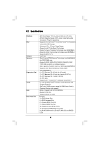
i5 Processors in the LGA1156 Package - Advanced V8 + 2 Power Phase Design - Supports Intel® Turbo Boost Technology - Supports Hyper-Threading Technology (see CAUTION 1) - Supports Untied Overclocking Technology (see CAUTION 2) - Supports EM64T CPU - Intel® P55 - Dual Channel DDR3 Memory Technology - ASRock P55 Pro | User Manual - Page 7
Wake Up Events - Supports jumperfree - SMBIOS 2.3.1 Support - CPU, VCCM, SB, VTT, VCCM REF, PCH_PLL Voltage Multi-adjustment - Supports I. O. T. (Intelligent Overclocking Technology) - Supports Smart BIOS - Drivers, Utilities, AntiVirus Software (Trial Version) - ASRock OC Tuner (see CAUTION - ASRock P55 Pro | User Manual - Page 8
55. 2. This motherboard supports Untied Overclocking Technology. Please read "Untied Overclocking Technology" on page 47 for details. 3. This motherboard supports Dual Channel Memory Technology. Before you implement Dual Channel Memory Technology, make sure to read the installation guide of memory - ASRock P55 Pro | User Manual - Page 9
BIOS setup menu to access ASRock Instant Flash. Just launch this tool and save the new BIOS file to your USB flash drive, floppy disk or hard drive, then you can update your BIOS adopt two different CPU cooler types, Socket LGA 775 and LGA 1156. Please be noticed that not all the 775 CPU Fan can be - ASRock P55 Pro | User Manual - Page 10
1.3 Two CrossFireXTM Graphics Card Support List (for Windows® XP / XP 64-bit / VistaTM / VistaTM 64-bit) Chipset Vendor ATI Model Name Chipset Name Driver MSI RX2600PRO-T2D256EZ Gigabyte GV-RX26T256HP-B ASUS EAH4350 SILENT/DI/512MD2/A ASUS EAH4870X2/HDTI/2G * Radeon HD 2600PRO Catalyst 9.1 - ASRock P55 Pro | User Manual - Page 11
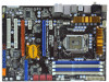
PLED PWRBTN PWRBTN 1 1 1 1 1 HDLED RESET 1 IR1 PANEL1 26 25 24 23 22 SATAII_5_6 SATAII_3_4 SATAII_1_2 7 8 9 10 11 12 13 14 15 16 17 18 19 20 21 1 PS2_USB_PWR1 Jumper 2 ATX 12V Power Connector (ATX12V1) 3 1156-Pin CPU Socket 4 2 x 240-pin DDR3 DIMM Slots (Dual Channel: DDR3_A2, DDR3_B2 - ASRock P55 Pro | User Manual - Page 12
) 9 Line In (Light Blue) ** 10 11 12 13 14 15 16 17 18 Front Speaker (Lime) Microphone (Pink) USB 2.0 Ports (USB45) USB 2.0 Ports (USB23) USB 2.0 Ports (USB01) Powered eSATAII/USB Connector Optical SPDIF Out Port Clear CMOS Switch (CLRCBTN) PS/2 Keyboard Port (Purple) * There are two LED next to - ASRock P55 Pro | User Manual - Page 13
Precautions Take note of the following precautions before you install motherboard components or change any motherboard settings. 1. Unplug the power cord from the wall socket before touching any component. 2. To avoid damaging the motherboard components due to static electricity, NEVER place your - ASRock P55 Pro | User Manual - Page 14
Intel 1156-Pin CPU, please follow the steps below. Load Plate Load Lever Contact Array Socket Body 1156-Pin Socket Overview Before you insert the 1156-Pin CPU into the socket, please check if the CPU surface is unclean or if there is any bent pin on the socket motherboard for after service. 14 - ASRock P55 Pro | User Manual - Page 15
key Pin1 Pin1 orientation key notch 1156-Pin CPU alignment key 1156-Pin Socket For proper inserting, please ensure to match the two orientation key notches of the CPU with the two alignment keys of the socket. Step 3-3. Carefully place the CPU into the socket by using a purely vertical motion - ASRock P55 Pro | User Manual - Page 16
with fan operation or contact other components. Please be noticed that this motherboard supports Combo Cooler Option (C.C.O.), which provides the flexible option to adopt two different CPU cooler types, Socket LGA 775 and LGA 1156. The white throughholes are for Socket LGA 1156 CPU fan. 16 - ASRock P55 Pro | User Manual - Page 17
2.5 Installation of Memory Modules (DIMM) This motherboard provides four 240-pin DDR3 (Double Data Rate 3) DIMM slots, and supports Dual Channel Memory Technology. For dual channel configuration, you always need to install identical (the same brand, speed, size and chiptype) DDR3 DIMM pair in the - ASRock P55 Pro | User Manual - Page 18
matches the break on the slot. notch break notch break The DIMM only fits in one correct orientation. It will cause permanent damage to the motherboard and the DIMM if you force the DIMM into the slot at incorrect orientation. Step 3. Firmly insert the DIMM into the slot until the retaining - ASRock P55 Pro | User Manual - Page 19
lane width graphics cards, or used to install PCI Express graphics cards to support CrossFireXTM function. PCIE4 (PCIE x16 slot; Orange) is used for PCI Express the installation. Step 2. Remove the system unit cover (if your motherboard is already installed in a chassis). Step 3. Remove the bracket - ASRock P55 Pro | User Manual - Page 20
ATITM CrossFireXTM driver updates. 1. If a customer incorrectly configures their system they will not see the performance benefits of CrossFireXTM. All three CrossFireXTM components, a CrossFireXTM Ready graphics card, a CrossFireXTM Ready motherboard and a CrossFireXTM Edition co-processor graphics - ASRock P55 Pro | User Manual - Page 21
Bridge is provided with the graphics card you purchase, not bundled with this motherboard. Please refer to your graphics card vendor for details.) CrossFire Bridge or Step 2. Connect the DVI monitor cable to the DVI connector on the Radeon graphics card on PCIE2 slot. (You may use the DVI - ASRock P55 Pro | User Manual - Page 22
utility to uninstall any previously installed Catalyst drivers prior to installation. Please check AMD website for ATITM driver updates. Step 3. Step 4. Step 5. Install the required drivers to your system. For Windows® XP OS: A. ATITM recommends Windows® XP Service Pack 2 or higher to be installed - ASRock P55 Pro | User Manual - Page 23
for identification or explanation and to the owners' benefit, without intent to infringe. * For further information of ATITM CrossFireXTM technology, please check AMD website for updates and details. 23 - ASRock P55 Pro | User Manual - Page 24
Display Feature This motherboard supports Surround Display upgrade. With the external add-on PCI Express VGA cards, you can easily enjoy the benefits of Surround Display feature. For the detailed instruction, please refer to the document at the following path in the Support CD: ..\ Surround Display - ASRock P55 Pro | User Manual - Page 25
) (39-pin IDE1, see p.11 No. 14) PIN1 IDE1 connect the blue end to the motherboard connect the black end to the IDE devices 80-conductor ATA 66/100/133 cable Note: Please refer to the instruction of your IDE device vendor for the details. Serial ATAII Connectors (SATAII_1_2: see p.11, No - ASRock P55 Pro | User Manual - Page 26
cable to the power connector of the power supply. Besides six default USB 2.0 ports on the I/O panel, there are three USB 2.0 headers on this motherboard. Each USB 2.0 header can support two USB 2.0 ports. This connector supports a Trusted Platform Module (TPM) system, which can securely store keys - ASRock P55 Pro | User Manual - Page 27
supports Jack Sensing, but the panel wire on the chassis must support HDA to function correctly. Please follow the instruction in our manual and chassis manual AC'97 audio panel. E. Enter BIOS Setup Utility. Enter Advanced Settings, and then select Chipset Configuration. Set the Front Panel - ASRock P55 Pro | User Manual - Page 28
+ PLEDPWRBTN# GND 1 DUMMY RESET# GND HDLEDHDLED+ This header motherboard provides 4-Pin CPU fan (Quiet Fan) support, the 3-Pin CPU fan still can work successfully even without the fan speed control function. If you plan to connect the 3-Pin CPU fan to the CPU fan connector on this motherboard - ASRock P55 Pro | User Manual - Page 29
one default IEEE 1394 port on the I/O panel, there is one IEEE 1394 header (FRONT_1394) on this motherboard. This IEEE 1394 header can support one IEEE 1394 port. This COM1 header supports a serial port module. HDMI_SPDIF Header (3-pin HDMI_SPDIF1) (see p.11 No. 29) 1 GND SPDIFOUT +5V HDMI_SPDIF - ASRock P55 Pro | User Manual - Page 30
HDMI_SPDIF Cable (Optional) C B A Please connect the black end (A) of HDMI_SPDIF cable to the HDMI_SPDIF header on the motherboard. Then connect the white end (B or C) of HDMI_SPDIF cable to the HDMI_SPDIF connector of HDMI VGA card. A. black end +5V SPDIFOUT GND B. white end (2-pin) C. - ASRock P55 Pro | User Manual - Page 31
2.11 Smart Switches This motherboard has three smart switches: power switch, reset switch and clear CMOS switch, allowing users to quickly turn on/off or reset the system or clear the CMOS values. Power Switch (PWRBTN) (see p.11 No. 20) Power Switch is a smart switch, allowing users to quickly - ASRock P55 Pro | User Manual - Page 32
chipset initialization. Re-enable CACHE. Verify that flat mode is enabled. Test base 512KB memory. Adjust policies and cache first 8MB. Set stack. Bootblock code is copied from ROM to lower system memory and control is given to it. BIOS now executes out of RAM. Both key sequence and OEM specific - ASRock P55 Pro | User Manual - Page 33
, and Silent logo modules. Early POST initialization of chipset registers. Uncompress and initialize any platform specific BIOS modules. Initialize System Management Interrupt. Initializes different devices through DIM. See DIM Code Checkpoints section of document for more information. Initializes - ASRock P55 Pro | User Manual - Page 34
to the user and gets the user response for error. 87 Execute BIOS setup if needed / requested. 8C Late POST initialization of chipset registers. 8D Build ACPI tables (if ACPI is supported) 8E Program the peripheral parameters. Enable/Disable NMI as selected 90 Late POST initialization - ASRock P55 Pro | User Manual - Page 35
Guide HDMI (High-Definition Multi-media Interface) is an all-digital audio/video specification motherboard with a HDMI_SPDIF header. This motherboard manual of HDMI VGA card vendor. Incorrect connection may cause permanent damage to this motherboard Otherwise, the motherboard and the user manual for - ASRock P55 Pro | User Manual - Page 36
guide. Some default setting of SATAII hard disks may not be at SATAII mode, which operate with the best performance. In order to enable SATAII function, please follow the below instruction 's website for details: http://www.hitachigst.com/hdd/support/download.htm The above examples are just for your - ASRock P55 Pro | User Manual - Page 37
adopts Intel® P55 chipset that supports Serial ATA (SATA) / Serial ATAII (SATAII) hard disks and RAID (RAID 0, RAID 1, RAID 10, RAID 5, and Intel Matrix Storage) functions. You may install SATA / SATAII hard disks on this motherboard for internal storage devices. This section will guide you - ASRock P55 Pro | User Manual - Page 38
2.16 Hot Plug and Hot Swap Functions for SATA / SATAII HDDs This motherboard supports Hot Plug and Hot Swap functions for SATA / SATAII in RAID / AHCI mode. Intel® P55 chipset provides hardware support for Advanced Host controller Interface (AHCI), a new programming interface for SATA host - ASRock P55 Pro | User Manual - Page 39
not be supported by the chipset because of its limitation, the SATA / SATAII Hot Plug support information of our motherboard is indicated in the product spec on our website: www.asrock.com 2. Make sure your SATA / SATAII HDD can support Hot Plug function from your dealer or HDD user manual. The SATA - ASRock P55 Pro | User Manual - Page 40
cable to (White) to the power supply 1x4-pin cable. the motherboard's SATAII connector. SATA power cable 1x4-pin power connector (White) Step attention, before you process the Hot Unplug: Please do follow below instruction sequence to process the Hot Unplug, improper procedure will cause the SATA - ASRock P55 Pro | User Manual - Page 41
, please follow below steps. STEP 1: Set up BIOS. A. Enter BIOS SETUP UTILITY Advanced screen Storage Configuration. B. Set the option "SATAII Operation Mode" to [RAID]. STEP 2: Make a SATA / SATAII Driver Diskette. A. Insert the Support CD into your optical drive to boot your system. B. During - ASRock P55 Pro | User Manual - Page 42
. Please refer to the document in the Support CD, "Guide to SATA Hard Disks Installation and RAID Configuration", which is located in the folder at the following path: .. \ RAID Installation Guide and the document in the support CD, "Guide to Intel Matrix Storage Manager", which is located in - ASRock P55 Pro | User Manual - Page 43
(R) ICH8R/ ICH9R/ICH10R/DO/PCH SATA RAID Controller - Windows XP64" for Windows® XP 64-bit. 5. Finish the Windows® installation and install all necessary drivers. 6. Install the Intel(R) Matrix Storage Manager software via the CD-ROM included with your motherboard or after downloading it from the - ASRock P55 Pro | User Manual - Page 44
the instruction to install Windows® VistaTM / VistaTM 64-bit OS on your system. When you see "Where do you want to install Windows?" page, please insert the ASRock Support CD into your optical drive, and click the "Load Driver" button on the left on the bottom to load the Intel® RAID drivers. Intel - ASRock P55 Pro | User Manual - Page 45
RAID functions, please follow below steps. Using SATA / SATAII HDDs with NCQ function STEP 1: Set Up BIOS. A. Enter BIOS driver. When prompted, insert the SATA / SATAII driver diskette containing the Intel® AHCI driver. After reading the floppy disk, the driver will be presented. Select the driver - ASRock P55 Pro | User Manual - Page 46
the instruction to install Windows® VistaTM / VistaTM 64-bit OS on your system. When you see "Where do you want to install Windows?" page, please insert the ASRock Support CD into your optical drive, and click the "Load Driver" button on the left on the bottom to load the Intel® AHCI drivers. Intel - ASRock P55 Pro | User Manual - Page 47
Technology This motherboard supports Untied Overclocking Technology, which means during overclocking, FSB enjoys better margin due to fixed PCI / PCIE buses. Before you enable Untied Overclocking function, please enter "Overclock Mode" option of BIOS setup to set the selection from [Auto] to [Manual - ASRock P55 Pro | User Manual - Page 48
reset button on the system chassis. You may also restart by turning the system off and then back on. Because the BIOS software is constantly being updated, the following BIOS OC Tweaker To set up overclocking features Advanced To set up the advanced BIOS features H/W Monitor To display - ASRock P55 Pro | User Manual - Page 49
/2009] BIOS Version : P55 Pro P1.00 Processor Type : Intel (R) Core (TM) CPU 870 @ 2.93GHz (64bit) Processor Speed : 2933MHz Microcode Update : 106E5/3 Cache Size : 1024KB Total Memory DDR3_1 DDR3_2 DDR3_3 DDR3_4 : 2048MB Single-Channel Memory Mode : None : None : 2048MB/667MHz (DDR3 1333 - ASRock P55 Pro | User Manual - Page 50
Frequency 22 [22] 4.800GT [Auto] DDR3_1333 [Auto] DRAM Timing Control ASRock Vdrop control CPU Voltage DRAM Voltage VTT Offset Voltage PCH Voltage [With VDrop] [Auto] [Auto] [Auto] [Auto] Overclocking may cause damage to your CPU and motherboard. It should be done at your own risk and expense - ASRock P55 Pro | User Manual - Page 51
] is selected, the motherboard will detect the memory module(s) inserted and assigns appropriate frequency automatically. You may select [Auto], [400MHz (DDR3 800)], [533MHz (DDR3 1066)], [667MHz (DDR3 1333)], [800MHz (DDR3 1600)], [933MHz (DDR3 1866)] or [1066MHz (DDR3 2133)]. DRAM Timing Control - ASRock P55 Pro | User Manual - Page 52
VDrop Control Use this to enable or disable ASRock VDrop control. Configuration options: [With VDrop] and [Without VDrop]. The default value is [With VDrop]. CPU Voltage Use this to select CPU Voltage. Configuration options: [Auto], [Manual] and [Overdrive Offset]. The default value is [Auto]. DRAM - ASRock P55 Pro | User Manual - Page 53
in below sections may cause system to malfunction. CPU Configuration Chipset Configuration ACPI Configuration Storage Configuration PCIPnP Configuration Floppy Configuration SuperIO Configuration USB Configuration BIOS Update Utility ASRock Instant Flash Select Screen Select Item Enter Go to - ASRock P55 Pro | User Manual - Page 54
this motherboard. Enhance Halt State All processors support the Halt State (C1). The C1 state is supported through the native processor instructions HLT and MWAIT and requires no hardware support from the chipset. In the C1 power state, the processor maintains the context of the system caches. Intel - ASRock P55 Pro | User Manual - Page 55
. Turbo mode allows processor cores to run faster than marked frequency in specific condition. The default value is [Enabled]. Intel (R) C-STATE tech. Intel (R) C-STATE tech. is achieved by making the power and thermal control unit part of the core logic and not part of the chipset as before - ASRock P55 Pro | User Manual - Page 56
BIOS SETUP UTILITY Advanced Chipset Settings Memory Remap Feature Primary Graphics Adapter Onboard HD Audio Front Panel OnBoard Lan Onboard 1394 [Disabled] [PCI] [Auto] [Enabled] [Enabled] [Enabled] Intelligent Energy Saver [Disabled] Intel VT-d Configuration ENABLE: Allow remapping - ASRock P55 Pro | User Manual - Page 57
3.4.3 ACPI Configuration BIOS SETUP UTILITY Advanced ACPI Configuration Suspend To RAM Restore on AC/Power Loss Ring-In Power On PCI Devices Power On PS / 2 Keyboard Power On RTC Alarm Power On ACPI HPET Table EUP Support [Disabled] [Power Off] [Disabled] [Disabled] [Disabled] [Disabled] [ - ASRock P55 Pro | User Manual - Page 58
motherboard to submit Windows® VistaTM certification. EUP Support Use this item to enable or disable EuP. The default value is [Auto]. 3.4.4 Storage Configuration BIOS ] [Not Detected] [Not Detected] [Not Detected] Options IDE RAID AHCI Disabled +F1 F9 F10 ESC Select Screen Select Item Change - ASRock P55 Pro | User Manual - Page 59
the "Primary IDE Master" as the example in the following instruction. BIOS SETUP UTILITY Advanced Primary IDE Master Device Vendor Size LBA Mode Block Data Transfer :Hard Disk :ST340014A :40.0 GB :Supported :16Sectors :4 :MultiWord DMA-2 :Ultra DMA-5 :Supported [Auto] [Auto] [Auto] [Auto] [Auto] - ASRock P55 Pro | User Manual - Page 60
to maximize the IDE hard disk data transfer rate. 3.4.5PCIPnP Configuration BIOS SETUP UTILITY Advanced Advanced PCI / PnP Settings PCI Latency Timer PCI default value unless the installed PCI expansion cards' specifications require other settings. PCI IDE BusMaster Use this item to enable - ASRock P55 Pro | User Manual - Page 61
Help Load Defaults Save and Exit Exit v02.54 (C) Copyright 1985-2005, American Megatrends, Inc. 3.4.7Super IO Configuration BIOS SETUP UTILITY Advanced Configure Super IO Chipset OnBoard Floppy Controller Serial Port Address Infrared Port Address [Enabled] [3F8 / IRQ4] [Disabled] Allow - ASRock P55 Pro | User Manual - Page 62
3.4.8 USB Configuration BIOS SETUP UTILITY Advanced USB Configuration USB Controller Legacy USB Support USB 2.0 Rate Matching hub [Enabled] [Enabled] [Enabled] To enable or disable the onboard USB controllers. +F1 F9 F10 ESC Select Screen Select Item Change Option General Help Load Defaults - ASRock P55 Pro | User Manual - Page 63
to monitor the status of the hardware on your system, including the parameters of the CPU temperature, motherboard temperature, CPU fan speed, chassis fan speed, and the critical voltage. BIOS SETUP UTILITY Main OC Tweaker Advanced H/W Monitor Boot Security Exit Hardware Health Event Monitoring - ASRock P55 Pro | User Manual - Page 64
F1 General Help F9 Load Defaults F10 Save and Exit ESC Exit v02.54 (C) Copyright 1985-2005, American Megatrends, Inc. 3.6.1 Boot Settings Configuration BIOS SETUP UTILITY Boot Boot Settings Configuration Full Screen Logo AddOn ROM Display Boot Logo Boot From Onboard LAN Bootup Num-Lock [Enabled - ASRock P55 Pro | User Manual - Page 65
option "Full Screen Logo". Configuration options: [Auto], [EuP], [Scenery] and [ASRock]. The default value is [Auto]. Boot From Onboard LAN Use this item to enable system. For the user password, you may also clear it. BIOS SETUP UTILITY Main OC Tweaker Advanced H/W Monitor Boot Security Exit - ASRock P55 Pro | User Manual - Page 66
Security Exit Exit Options Save Changes and Exit Discard Changes and Exit Discard Changes Load BIOS Defaults Load Performance Setup Default (IDE/SATA) Load Performance Setup AHCI Mode Load Performance Setup RAID Mode Load Power Saving Setup Default Exit system setup after saving the changes. F10 - ASRock P55 Pro | User Manual - Page 67
install the necessary drivers to activate the devices. 4.2.3 Utilities Menu The Utilities Menu shows the applications software that the motherboard supports. Click on a specific item then follow the installation wizard to install it. 4.2.4 Contact Information If you need to contact ASRock or want to
-
 1
1 -
 2
2 -
 3
3 -
 4
4 -
 5
5 -
 6
6 -
 7
7 -
8
-
9
-
10
-
11
-
12
-
13
-
14
-
15
-
16
-
17
-
18
-
19
-
20
-
21
-
22
-
23
-
24
-
25
-
26
-
27
-
28
-
29
-
30
-
31
-
32
-
33
-
34
-
35
-
36
-
37
-
38
-
39
-
40
-
41
-
42
-
43
-
44
-
45
-
46
-
47
-
48
-
49
-
50
-
51
-
52
-
53
-
54
-
55
-
56
-
57
-
58
-
59
-
60
-
61
-
62
-
63
-
64
-
65
-
66
-
67
 |
 |

1
P55 Pro
User Manual
Version 1.1
Published August 2009
Copyright©2009 ASRock INC. All rights reserved.