ASRock P55DE Pro User Manual
ASRock P55DE Pro Manual
 |
View all ASRock P55DE Pro manuals
Add to My Manuals
Save this manual to your list of manuals |
ASRock P55DE Pro manual content summary:
- ASRock P55DE Pro | User Manual - Page 1
P55DE Pro / P55DE3 User Manual Version 1.0 Published September 2009 Copyright©2009 ASRock INC. All rights reserved. 1 - ASRock P55DE Pro | User Manual - Page 2
means, except duplication of documentation by the purchaser for backup purpose, without written consent of ASRock Inc. Products and corporate names appearing in this manual may or may not be registered trademarks or copyrights of their respective companies, and are used only for identification or - ASRock P55DE Pro | User Manual - Page 3
Contents 5 1.2 Specifications 6 1.3 Two CrossFireXTM Graphics Card Support List 10 1.4 Motherboard Layout 11 1.5 I/O Panel SATAII HDDs 33 2.15 SATA / SATAII HDD Hot Plug Feature and Operation Guide 34 2.16 Driver Installation Guide 36 2.17 Installing Windows® XP / XP 64-bit / VistaTM / - ASRock P55DE Pro | User Manual - Page 4
60 3.6 Boot Screen 61 3.6.1 Boot Settings Configuration 61 3.7 Security Screen 62 3.8 Exit Screen 63 4 Software Support 64 4.1 Install Operating System 64 4.2 Support CD Information 64 4.2.1 Running Support CD 64 4.2.2 Drivers Menu 64 4.2.3 Utilities Menu 64 4.2.4 Contact Information 64 4 - ASRock P55DE Pro | User Manual - Page 5
about the model you are using. www.asrock.com/support/index.asp 1.1 Package Contents ASRock P55DE Pro / P55DE3 Motherboard (ATX Form Factor: 12.0-in x 8.3-in, 30.5 cm x 21.1 cm) ASRock P55DE Pro / P55DE3 Quick Installation Guide ASRock P55DE Pro / P55DE3 Support CD 2 x Serial ATA (SATA) Data Cables - ASRock P55DE Pro | User Manual - Page 6
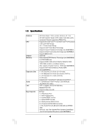
P55DE Pro) - Supports the Intel® CoreTM i7 and Intel® CoreTM i5 Processors in the LGA1156 Package - V4 + 1 Power Phase Design - Supports Intel® Turbo Boost Technology - Supports Hyper-Threading Technology (see CAUTION 1) - Supports /Central/Bass/ Line in/Front Speaker/Microphone (see CAUTION 6) 6 - ASRock P55DE Pro | User Manual - Page 7
" - ACPI 1.1 Compliance Wake Up Events - Supports jumperfree - SMBIOS 2.3.1 Support - CPU, VCCM, PCH, VTT Voltage Multi-adjustment - Supports I. O. T. (Intelligent Overclocking Technology) - Supports Smart BIOS - Drivers, Utilities, AntiVirus Software (Trial Version) - ASRock OC Tuner (see CAUTION - ASRock P55DE Pro | User Manual - Page 8
detailed product information, please visit our website: http://www.asrock. supports Dual Channel Memory Technology. Before you implement Dual Channel Memory Technology, make sure to read the installation guide 9. It is a user-friendly ASRock overclocking tool which allows you to surveil your system - ASRock P55DE Pro | User Manual - Page 9
or press key to BIOS setup menu to access ASRock Instant Flash. Just launch this tool and save the new BIOS file to your USB flash drive, the 775 CPU Fan can be used. 16. EuP, stands for Energy Using Product, was a provision regulated by European Union to define the power consumption for the - ASRock P55DE Pro | User Manual - Page 10
1.3 Two CrossFireXTM Graphics Card Support List (for Windows® XP / XP 64-bit / VistaTM / VistaTM 64-bit) 9.7 * For the latest updates of the supported PCI Express VGA card list for CrossFireXTM Mode, please visit our website for details. ASRock website: http://www.asrock.com/support/index.htm 10 - ASRock P55DE Pro | User Manual - Page 11
USB 2.0 T: USB2 B: USB3 USB 2.0 T: USB0 B: USB1 USB 2.0 T: USB4 B: USB5 Top: RJ-45 eSATAII5/USB6 eSATAII6/USB7 Top: SIDE SPK Center: REAR SPK Bottom: CTR BASS 30 29 28 27 26 25 24 Top: LINE IN Center: FRONT Bottom: MIC IN CD1 LAN PHY HD_AUDIO1 PWR_FAN1 CPU_FAN1 PCIE1 CrossFireX DDR3 2400 - ASRock P55DE Pro | User Manual - Page 12
* 2 LAN RJ-45 Port 3 Side Speaker (Gray) 4 Rear Speaker (Black) 5 Central / Bass (Orange) 6 Line In (Light Blue) ** 7 Front Speaker (Lime) 8 Microphone (Pink) 12 audio header. After restarting your computer, you will find "Mixer" tool on your system. Please select "Mixer ToolBox" , click "Enable - ASRock P55DE Pro | User Manual - Page 13
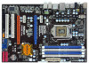
Chapter 2: Installation This is an ATX form factor (12.0" x 8.3", 30.5 x 21.1 cm) motherboard. Before you install the motherboard, study the configuration of your chassis to ensure that the motherboard fits into it. Make sure to unplug the power cord before installing or removing the motherboard. - ASRock P55DE Pro | User Manual - Page 14
to use the cap tab to handle and avoid kicking off the PnP cap. 2. This cap must be placed if returning the motherboard for after service. 14 - ASRock P55DE Pro | User Manual - Page 15
Step 3. Insert the 1156-Pin CPU: Step 3-1. Hold the CPU by the edge where is marked with black line. black line Step 3-2. Orient the CPU with IHS (Integrated Heat Sink) up. Locate Pin1 and the two orientation key notches. orientation key notch alignment key Pin1 Pin1 orientation key notch 1156 - ASRock P55DE Pro | User Manual - Page 16
11, No. 31). For proper installation, please kindly refer to the instruction manuals of your CPU fan and heatsink. Below is an example to illustrate the or contact other components. Please be noticed that this motherboard supports Combo Cooler Option (C.C.O.), which provides the flexible option to - ASRock P55DE Pro | User Manual - Page 17
2.5 Installation of Memory Modules (DIMM) This motherboard provides four 240-pin DDR3 (Double Data Rate 3) DIMM slots, and supports Dual Channel Memory Technology. For dual channel configuration, you always need to install identical (the same brand, speed, size and chiptype) DDR3 DIMM pair in - ASRock P55DE Pro | User Manual - Page 18
Installing a DIMM Please make sure to disconnect power supply before adding or removing DIMMs or the system components. Step 1. Step 2. Unlock a DIMM slot by pressing the retaining clips outward. Align a DIMM on the slot such that the notch on the DIMM matches the break on the slot. notch break - ASRock P55DE Pro | User Manual - Page 19
lane width graphics cards, or used to install PCI Express graphics cards to support CrossFireXTM function. PCIE4 (PCIE x16 slot; Orange) is used for PCI Express card, etc., or used to install PCI Express graphics cards to support CrossFireXTM function. 1. In single VGA card mode, it is recommended - ASRock P55DE Pro | User Manual - Page 20
supported with Windows® XP with Service Pack 2 and VistaTM OS. Quad CrossFireXTM feature are supported motherboard and a CrossFireXTM Edition co-processor graphics card, must be installed please refer to ATITM graphics card manuals for detailed installation guide. Step 1. Insert one Radeon graphics - ASRock P55DE Pro | User Manual - Page 21
Step 2. Connect two Radeon graphics cards by installing CrossFire Bridge on CrossFire Bridge Interconnects on the top of Radeon graphics cards. (CrossFire Bridge is provided with the graphics card you purchase, not bundled with this motherboard. Please refer to your graphics card vendor for details - ASRock P55DE Pro | User Manual - Page 22
Step 3. Step 4. Step 5. Install the required drivers to your system. For Windows® XP OS: A. ATITM recommends Windows® XP Service Pack 2 or higher to be installed (If you have Windows® XP Service Pack 2 or higher installed in your system, there is no need to download it again): http://www.microsoft - ASRock P55DE Pro | User Manual - Page 23
benefit of CrossFireXTM feature. Step 7. You can freely enjoy the benefit of CrossFireXTM or Quad CrossFireXTM feature. * CrossFireXTM appearing here is a registered trademark of ATITM Technologies Inc., and is used only for identification or explanation and to the owners' benefit, without intent to - ASRock P55DE Pro | User Manual - Page 24
Express VGA cards, you can easily enjoy the benefits of Surround Display feature. For the detailed instruction, please refer to the document at the following path in the Support CD: ..\ Surround Display Information 2.9 Jumpers Setup The illustration shows how jumpers are setup. When the jumper - ASRock P55DE Pro | User Manual - Page 25
USB_PWR USB_PWR P-11 P+11 GND DUMMY 1 GND P+10 P-10 USB_PWR USB_PWR P-9 P+9 GND DUMMY 1 GND P+8 P-8 USB_PWR 25 These four Serial ATAII (SATAII) connectors support SATA data cables for internal storage devices. The current SATAII interface allows up to 3.0 Gb/s data transfer rate. Either end of the - ASRock P55DE Pro | User Manual - Page 26
allows convenient connection and control of audio devices. 1. High Definition Audio supports Jack Sensing, but the panel wire on the chassis must support HDA to function correctly. Please follow the instruction in our manual and chassis manual to install your system. 2. If you use AC'97 audio - ASRock P55DE Pro | User Manual - Page 27
connect a CPU fan cable to this connector and match the black wire to the ground pin. Though this motherboard provides 4-Pin CPU fan (Quiet Fan) support, the 3-Pin CPU fan still can work successfully even without the fan speed control function. If you plan to connect the 3-Pin CPU fan to - ASRock P55DE Pro | User Manual - Page 28
) (see p.11 No. 32) 4-Pin ATX 12V Power Supply Installation 1 5 RRXD1 DDTR#1 DDSR#1 CCTS#1 1 RRI#1 RRTS#1 GND TTXD1 DDCD#1 This COM1 header supports a serial port module. 1 GND SPDIFOUT +5V HDMI_SPDIF header, providing SPDIF audio output to HDMI VGA card, allows the system to connect HDMI - ASRock P55DE Pro | User Manual - Page 29
HDMI_SPDIF Cable (Optional) C B A Please connect the black end (A) of HDMI_SPDIF cable to the HDMI_SPDIF header on the motherboard. Then connect the white end (B or C) of HDMI_SPDIF cable to the HDMI_SPDIF connector of HDMI VGA card. A. black end B. white end (2-pin) C. white end (3-pin) +5V - ASRock P55DE Pro | User Manual - Page 30
. For the proper installation of HDMI VGA card, please refer to the installation guide on page 19. Step 2. Connect the black end (A) of HDMI_SPDIF cable to the of PCI Express VGA card. Please refer to the VGA card user manual for connector usage in advance. Connect the HDMI output connector on HDMI - ASRock P55DE Pro | User Manual - Page 31
Please use the Feature Tool, a DOS-bootable tool, for changing various ATA features. Please visit HITACHI's website for details: http://www.hitachigst.com/hdd/support/download.htm The above examples are just for your reference. For different SATAII hard disk products of different vendors, the - ASRock P55DE Pro | User Manual - Page 32
(SATAII) Hard Disks Installation This motherboard adopts Intel® P55 chipset that supports Serial ATA (SATA) / Serial ATAII (SATAII) hard disks and RAID hard disks on this motherboard for internal storage devices. This section will guide you to install the SATA / SATAII hard disks. STEP 1: Install - ASRock P55DE Pro | User Manual - Page 33
Hot Plug and Hot Swap functions for SATA / SATAII in RAID / AHCI mode. Intel® P55 chipset provides hardware support for Advanced Host controller Interface (AHCI), a new programming interface for SATA host controllers developed thru a joint industry effort. NOTE What is Hot Plug Function? If - ASRock P55DE Pro | User Manual - Page 34
information of our motherboard is indicated in the product spec on our website: www.asrock.com 2. Make sure your SATA / SATAII HDD can support Hot Plug function from your dealer or HDD user manual. The SATA / SATAII HDD, which cannot support Hot Plug function, will be damaged under the Hot Plug - ASRock P55DE Pro | User Manual - Page 35
the SATA / SATAII HDD. How to Hot Unplug a SATA / SATAII HDD: Points of attention, before you process the Hot Unplug: Please do follow below instruction sequence to process the Hot Unplug, improper procedure will cause the SATA / SATAII HDD damage and data loss. Step 1 Unplug SATA data cable from - ASRock P55DE Pro | User Manual - Page 36
2.16 Driver Installation Guide To install the drivers to your system, please insert the support CD to your optical drive first. Then, the drivers compatible to your system can be auto-detected and listed on the support CD driver page. Please follow the order from up to bottom side to install those - ASRock P55DE Pro | User Manual - Page 37
Hard Disks Installation and RAID Configuration", which is located in the folder at the following path: .. \ RAID Installation Guide and the document in the support CD, "Guide to Intel Matrix Storage Manager", which is located in the folder at the following path: .. \ Intel Matrix Storage Manager - ASRock P55DE Pro | User Manual - Page 38
install. You may select: "Intel(R) ICH8R/ICH9R/ICH10R/DO/PCH SATA RAID Controller - Windows XP/2000" for Windows® 2000/XP or "Intel(R) ICH8R/ ICH9R/ICH10R/DO/PCH SATA RAID Controller - Windows XP64" for Windows® XP 64-bit. 5. Finish the Windows® installation and install all necessary drivers. 6. - ASRock P55DE Pro | User Manual - Page 39
instruction to install Windows® VistaTM / VistaTM 64-bit OS on your system. When you see "Where do you want to install Windows?" page, please insert the ASRock Support the following path: .. \ RAID Installation Guide and the document in the support CD, "Guide to Intel Matrix Storage Manager", which - ASRock P55DE Pro | User Manual - Page 40
2.18 Installing Windows® XP / XP 64-bit / VistaTM / VistaTM 64-bit Without RAID Functions If you want to install Windows® XP / XP 64-bit / VistaTM / VistaTM 64-bit OS on your SATA / SATAII HDDs without RAID functions, please follow below procedures according to the OS you install. 2.18.1 Installing - ASRock P55DE Pro | User Manual - Page 41
disk into the optical drive to boot your system, and follow the instruction to install Windows® VistaTM / VistaTM 64-bit OS on your system. When you see "Where do you want to install Windows?" page, please insert the ASRock Support CD into your optical drive, and click the "Load Driver" button on - ASRock P55DE Pro | User Manual - Page 42
motherboard supports Untied Overclocking Technology, which means during overclocking, FSB enjoys better margin due to fixed PCI / PCIE buses. Before you enable Untied Overclocking function, please enter "Overclock Mode" option of BIOS setup to set the selection from [Auto] to [Manual]. Therefore - ASRock P55DE Pro | User Manual - Page 43
Chapter 3: BIOS SETUP UTILITY 3.1 Introduction This section explains how to use the BIOS SETUP UTILITY to configure your system. The BIOS FWH chip on the motherboard stores the BIOS SETUP UTILITY. You may run the BIOS SETUP UTILITY when you start up the computer. Please press or during - ASRock P55DE Pro | User Manual - Page 44
System Overview System Time System Date [14:00:09] [Fri 09/25/2009] BIOS Version : P55DE Pro P1.00 Processor Type : Intel (R) Core (TM) CPU 870 @ 2.93GHz (64bit) Processor Speed : 2933MHz Microcode Update : 106E5/3 Cache Size : 1024KB Total Memory DDR3_A2 DDR3_A1 DDR3_B1 DDR3_B1 : 2048MB - ASRock P55DE Pro | User Manual - Page 45
Overview System Time System Date [14:00:09] [Fri 09/25/2009] BIOS Version : P55DE3 P1.00 Processor Type : Intel (R) Core (TM) CPU 870 @ 2.93GHz (64bit) Processor Speed : 2933MHz Microcode Update : 106E5/3 Cache Size : 1024KB Total Memory DDR3_A2 DDR3_A1 DDR3_B1 DDR3_B1 : 2048MB Single - ASRock P55DE Pro | User Manual - Page 46
[Enabled] [Auto] [Auto] [Auto] [Auto] DRAM Timing Control ASRock VDrop Control [With VDrop] Overclocking may cause damage to your CPU and Configuration options: [Auto], [Manual], [I.O.T.] and [Optimized]. The default value is [Auto]. If you select [Manual], Untied Overclocking function is - ASRock P55DE Pro | User Manual - Page 47
If you select [I.O.T.] (Intelligent Overclocking Technology), the system will automatically enable the overclocking function when your CPU is heavy loaded. BCLK Frequency (MHz) Use this option to adjust BCLK (Internal Base Clock) frequency. PCIE Frequency (MHz) Use this option to adjust PCIE - ASRock P55DE Pro | User Manual - Page 48
VDrop Control Use this to enable or disable ASRock VDrop control. Configuration options: [With VDrop] and [Without VDrop]. The default value is [With VDrop]. CPU Voltage Use this to select CPU Voltage. Configuration options: [Auto], [Manual] and [Overdrive Offset]. The default value is [Auto]. 48 - ASRock P55DE Pro | User Manual - Page 49
DRAM Voltage Use this to select DRAM Voltage. Configuration options: [Auto], [1.47V] to [2.40V]. The default value is [Auto]. VTT Offset Voltage Use this to select VTT Offset Voltage. Configuration options: [Auto], [1.11V] to [1.55V]. The default value is [Auto]. PCH Voltage Use this to select PCH - ASRock P55DE Pro | User Manual - Page 50
Megatrends, Inc. Setting wrong values in this section may cause the system to malfunction. ASRock Instant Flash ASRock Instant Flash is a BIOS flash utility embedded in Flash ROM. This convenient BIOS update tool allows you to update system BIOS without entering operating systems first like MS-DOS - ASRock P55DE Pro | User Manual - Page 51
of this motherboard. Enhance Halt State All processors support the Halt State (C1). The C1 state is supported through the native processor instructions HLT and MWAIT and requires no hardware support from the chipset. In the C1 power state, the processor maintains the context of the system caches - ASRock P55DE Pro | User Manual - Page 52
be hidden if the current CPU does not support Intel (R) SpeedStep(tm) tech.. Please note the power and thermal management flow into the processor allows us to use a hardware coordination mechanism option will program into C State package limit register. This itemappears only when you set the item - ASRock P55DE Pro | User Manual - Page 53
3.4.2Chipset Configuration BIOS SETUP UTILITY Advanced Chipset Settings Primary Graphics Adapter Onboard HD Audio Front Panel CD-In OnBoard Lan [PCI] [Auto] [Enabled] [Enabled] [Enabled] Intel VT-d Configuration ENABLE: Allow remapping of overlapped PCI memory above the total physical memory. - ASRock P55DE Pro | User Manual - Page 54
RAM Use this item to select whether to auto-detect or disable the Suspend-toRAM feature. Select [Auto] will enable this feature if the OS supports it. If you set this item to [Disabled], the function "Repost Video on STR Resume" will be hidden. Check Ready Bit Use this item to - ASRock P55DE Pro | User Manual - Page 55
"Link Power Management" will appear. AHCI (Advanced Host Controller Interface) supports NCQ and other new features that will improve SATA disk performance but the "Primary IDE Master" as the example in the following instruction. BIOS SETUP UTILITY Advanced Primary IDE Master Device Type LBA/Large - ASRock P55DE Pro | User Manual - Page 56
TYPE Use this item to configure the type of the IDE device that you specify. Configuration options: [Not Installed], [Auto], [CD/DVD], and [ARMD]. [Not Installed]: Select [Not Installed] to disable the use of IDE device. [Auto]: Select [Auto] to automatically detect the hard disk drive. After - ASRock P55DE Pro | User Manual - Page 57
Advanced PCI / PnP Settings PCI Latency Timer PCI IDE BusMaster [64] [Enabled] Value in units of PCI clocks for PCI device latency timer register. +F1 F9 F10 ESC Select Screen Select Item Change Option General Help Load Defaults Save and Exit Exit v02.54 (C) Copyright 1985-2005, American - ASRock P55DE Pro | User Manual - Page 58
3.4.6Floppy Configuration In this section, you may configure the type of your floppy drive. BIOS SETUP UTILITY Advanced Floppy Configuration Floppy A [1.44 MB 312"] Select the type of floppy drive connected to the system. +F1 F9 F10 ESC Select Screen Select Item Change Option General Help Load - ASRock P55DE Pro | User Manual - Page 59
-2005, American Megatrends, Inc. USB Controller Use this item to enable or disable the use of USB controller. Legacy USB Support Use this option to select legacy support for USB devices. There are four configuration options: [Enabled], [Auto], [Disabled] and [BIOS Setup Only]. The default value is - ASRock P55DE Pro | User Manual - Page 60
[Automatic mode]. The default is value [Full On]. Chassis Fan Setting This allows you to set the chassis fan speed. Configuration options: [Full On] and [Manual mode]. The default is value [Full On]. 60 - ASRock P55DE Pro | User Manual - Page 61
3.6 Boot Screen In this section, it will display the available devices on your system for you to configure the boot settings and the boot priority. BIOS SETUP UTILITY Main OC Tweaker Advanced H/W Monitor Boot Security Exit Boot Settings Boot Settings Configuration Configure Settings during - ASRock P55DE Pro | User Manual - Page 62
to select logo in POST screen. This option only appears when you enable the option "Full Screen Logo". Configuration options: [Auto], [EuP], [Scenery] and [ASRock]. The default value is [Auto]. Boot From Onboard LAN Use this item to enable or disable the Boot From Onboard LAN feature. Boot Up Num - ASRock P55DE Pro | User Manual - Page 63
3.8 Exit Screen BIOS SETUP UTILITY Main OC Tweaker Advanced H/W Monitor Boot Security Exit Exit Options Save Changes and Exit Discard Changes and Exit Discard Changes Load BIOS Defaults Load Performance Setup Default (IDE/SATA) Load Performance Setup AHCI Mode Load Performance Setup RAID Mode Load - ASRock P55DE Pro | User Manual - Page 64
applications software that the motherboard supports. Click on a specific item then follow the installation wizard to install it. 4.2.4 Contact Information If you need to contact ASRock or want to know more about ASRock, welcome to visit ASRock's website at http://www.asrock.com; or you may contact
-
 1
1 -
 2
2 -
 3
3 -
 4
4 -
 5
5 -
 6
6 -
 7
7 -
8
-
9
-
10
-
11
-
12
-
13
-
14
-
15
-
16
-
17
-
18
-
19
-
20
-
21
-
22
-
23
-
24
-
25
-
26
-
27
-
28
-
29
-
30
-
31
-
32
-
33
-
34
-
35
-
36
-
37
-
38
-
39
-
40
-
41
-
42
-
43
-
44
-
45
-
46
-
47
-
48
-
49
-
50
-
51
-
52
-
53
-
54
-
55
-
56
-
57
-
58
-
59
-
60
-
61
-
62
-
63
-
64
 |
 |
1
P55DE Pro /
P55DE3
User Manual
Version 1.0
Published September 2009
Copyright©2009 ASRock INC. All rights reserved.