ASRock P55M Pro User Manual
ASRock P55M Pro Manual
 |
View all ASRock P55M Pro manuals
Add to My Manuals
Save this manual to your list of manuals |
ASRock P55M Pro manual content summary:
- ASRock P55M Pro | User Manual - Page 1
P55M Pro User Manual Version 1.1 Published August 2009 Copyright©2009 ASRock INC. All rights reserved. 1 - ASRock P55M Pro | User Manual - Page 2
without notice, and should not be constructed as a commitment by ASRock. ASRock assumes no responsibility for any errors or omissions that may appear in this manual. With respect to the contents of this manual, ASRock does not provide warranty of any kind, either expressed this motherboard contains - ASRock P55M Pro | User Manual - Page 3
Card Support List 10 1.4 Motherboard Layout 11 1.5 I/O Panel 12 2 Installation 14 2.1 Screw Holes 14 2.2 Pre-installation Precautions 14 2.3 CPU Installation 15 2.4 Installation of Heatsink and CPU fan 17 2.5 Installation of Memory Modules (DIMM 18 2.6 Expansion Slots (PCI and PCI Express - ASRock P55M Pro | User Manual - Page 4
Windows® VistaTM / VistaTM 64-bit Without RAID Functions 42 2.19 Untied Overclocking Technology 43 3 BIOS SETUP UTILITY 44 3.1 Introduction 44 3.1.1 BIOS Menu Bar 44 3.1.2 Navigation Keys 45 3.2 Main Screen 45 3.3 OC Tweaker Screen 45 3.4 Advanced Screen 49 3.4.1 CPU Configuration - ASRock P55M Pro | User Manual - Page 5
of this manual occur, the updated version will be available on ASRock website without further notice. You may find the latest VGA cards and CPU support lists on ASRock website as well. ASRock website http://www.asrock.com If you require technical support related to this motherboard, please visit - ASRock P55M Pro | User Manual - Page 6
CoreTM i5 Processors in the LGA1156 Package - 4 + 1 Power Phase Design - Supports Intel® Turbo Boost Technology - Supports Hyper-Threading Technology (see CAUTION 1) - Supports Untied Overclocking Technology (see CAUTION 2) - Supports EM64T CPU - Intel® P55 - Dual Channel DDR3 Memory Technology (see - ASRock P55M Pro | User Manual - Page 7
Support - CPU, VCCM, PCH,VTT Voltage Multi-adjustment - Supports I. O. T. (Intelligent Overclocking Technology) - Supports Smart BIOS - Drivers, Utilities, AntiVirus Software (Trial Version) - ASRock OC Tuner (see CAUTION 9) - Intelligent Energy Saver (see CAUTION 10) - Instant Boot - ASRock Instant - ASRock P55M Pro | User Manual - Page 8
Windows® VistaTM 64-bit with 64-bit CPU, there is no such limitation. 5. For those CPU that only support up to DDR3 1333, the XMP DDR3 1600 is supported through overclocking. 6. For microphone input, this motherboard supports both stereo and mono modes. For audio output, this motherboard supports - ASRock P55M Pro | User Manual - Page 9
Intelligent Energy Saver. ASRock website: http://www.asrock.com/feature/IES/index.html 11. ASRock Instant Flash is a BIOS flash utility embedded in Flash ROM. This convenient BIOS update tool allows you to update system BIOS without entering operating systems first like MS-DOS or Windows®. With this - ASRock P55M Pro | User Manual - Page 10
Catalyst 9.1 * The graphics cards with * mark are supported under Windows® VistaTM / VistaTM 64-bit only. * For the latest updates of the supported PCI Express VGA card list for CrossFireXTM Mode, please visit our website for details. ASRock website: http://www.asrock.com/support/index.htm 10 - ASRock P55M Pro | User Manual - Page 11
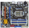
P55M Pro HDMI_SPDIF1 PCI Express 2.0 PCIE1 AUDIO CODEC PCIE2 CMOS Battery Super I/O FLOPPY1 PCIE3 COM1 1 PCI1 LPT1 1 TPM1 1 IR1 1 IDE1 SATAII_4 1394a VIA VT6330 Intel P55 16Mb BIOS 1, Purple) 5 1156-Pin CPU Socket 22 Clear CMOS Jumper (CLRCMOS1) 6 2 x 240-pin DDR3 DIMM Slots 23 - ASRock P55M Pro | User Manual - Page 12
(Orange) 8 Line In (Light Blue) ** 9 Front Speaker (Lime) 10 Microphone (Pink) 11 Powered eSATAII/USB Connectors 12 USB 2.0 Ports (USB45) in accordance with the type of speaker you use. TABLE for Audio Output Connection Audio Output Channels Front Speaker Rear Speaker Central / Bass Side Speaker - ASRock P55M Pro | User Manual - Page 13
header. After restarting your computer, you will find "VIA HD Audio Deck" tool on your system. Please follow below instructions according to the OS you install. For Windows® XP / XP 64-bit OS: Please click "VIA HD Audio Deck" icon , and click "Speaker". Then you are allowed to select "2 Channel - ASRock P55M Pro | User Manual - Page 14
Precautions Take note of the following precautions before you install motherboard components or change any motherboard settings. 1. Unplug the power cord from the wall socket before touching any component. 2. To avoid damaging the motherboard components due to static electricity, NEVER place your - ASRock P55M Pro | User Manual - Page 15
Intel 1156-Pin CPU, please follow the steps below. Load Plate Load Lever Contact Array Socket Body 1156-Pin Socket Overview Before you insert the 1156-Pin CPU into the socket, please check if the CPU surface is unclean or if there is any bent pin on the socket motherboard for after service. 15 - ASRock P55M Pro | User Manual - Page 16
key Pin1 Pin1 orientation key notch 1156-Pin CPU alignment key 1156-Pin Socket For proper inserting, please ensure to match the two orientation key notches of the CPU with the two alignment keys of the socket. Step 3-3. Carefully place the CPU into the socket by using a purely vertical motion - ASRock P55M Pro | User Manual - Page 17
with fan operation or contact other components. Please be noticed that this motherboard supports Combo Cooler Option (C.C.O.), which provides the flexible option to adopt two different CPU cooler types, Socket LGA 775 and LGA 1156. The white throughholes are for Socket LGA 1156 CPU fan. 17 - ASRock P55M Pro | User Manual - Page 18
module or three memory modules are installed in the DDR3 DIMM slots on this motherboard, it is unable to activate the Dual Channel Memory Technology. 3. It is not allowed to install a DDR or DDR2 memory module into DDR3 slot;otherwise, this motherboard and DIMM may be damaged. 4. Please install the - ASRock P55M Pro | User Manual - Page 19
matches the break on the slot. notch break notch break The DIMM only fits in one correct orientation. It will cause permanent damage to the motherboard and the DIMM if you force the DIMM into the slot at incorrect orientation. Step 3. Firmly insert the DIMM into the slot until the retaining - ASRock P55M Pro | User Manual - Page 20
1 PCI slot and 3 PCI Express slots on this motherboard. PCI slot: PCI slot is used to install expansion cards that have the 32-bit PCI interface. PCIE slots: PCIE1 (PCIE x16 slot; Blue) is used for PCI Express x16 lane width graphics cards, or used to install PCI Express graphics cards to support - ASRock P55M Pro | User Manual - Page 21
feature are supported with Windows® VistaTM OS only. Please check AMD website for ATITM CrossFireXTM driver updates. 1. If a customer incorrectly configures their system they will not see the performance benefits of CrossFireXTM. All three CrossFireXTM components, a CrossFireXTM Ready graphics card - ASRock P55M Pro | User Manual - Page 22
Radeon graphics cards by installing CrossFire Bridge on CrossFire Bridge Interconnects on the top of Radeon graphics cards. (CrossFire Bridge is provided with the graphics card you purchase, not bundled with this motherboard. Please refer to your graphics card vendor for details.) CrossFire Bridge - ASRock P55M Pro | User Manual - Page 23
to installation. Please check AMD website for ATITM driver updates. Step 3. Step 4. Step 5. Install the required drivers to your system. For Windows® XP OS: A. ATITM recommends Windows® XP Service Pack 2 or higher to be installed (If you have Windows® XP Service Pack 2 or higher installed in your - ASRock P55M Pro | User Manual - Page 24
feature. * CrossFireXTM appearing here is a registered trademark of ATITM Technologies Inc., and is used only for identification or explanation and to the owners' benefit, without intent to infringe. * For further information of ATITM CrossFireXTM technology, please check AMD website for - ASRock P55M Pro | User Manual - Page 25
Display Feature This motherboard supports Surround Display upgrade. With the external add-on PCI Express VGA cards, you can easily enjoy the benefits of Surround Display feature. For the detailed instruction, please refer to the document at the following path in the Support CD: ..\ Surround Display - ASRock P55M Pro | User Manual - Page 26
instruction of your IDE device vendor for the details. Serial ATAII Connectors (SATAII_1: see p.11, No. 11) (SATAII_2: see p.11, No. 10) (SATAII_3: see p.11, No. 12) (SATAII_4: see p.11, No. 13) SATAII_4 SATAII_2 SATAII_3 SATAII_1 These four Serial ATAII (SATAII) connectors support SATA data - ASRock P55M Pro | User Manual - Page 27
18) (9-pin USB8_9) (see p.11 No. 19) USB_PWR P-11 P+11 GND DUMMY 1 GND P+10 P-10 USB_PWR USB_PWR P-9 P+9 GND DUMMY 1 GND P+8 P-8 USB_PWR Print Port Header (25-pin LPT1) ( , there are three USB 2.0 headers on this motherboard. Each USB 2.0 header can support two USB 2.0 ports. This is an interface - ASRock P55M Pro | User Manual - Page 28
cable that allows convenient connection and control of audio devices. 1. High Definition Audio supports Jack Sensing, but the panel wire on the chassis must support HDA to function correctly. Please follow the instruction in our manual and chassis manual to install your system. 2. If you use AC - ASRock P55M Pro | User Manual - Page 29
to the ground pin. Though this motherboard provides 4-Pin CPU fan (Quiet Fan) support, the 3-Pin CPU fan still can work successfully even without the fan speed control function. If you plan to connect the 3-Pin CPU fan to the CPU fan connector on this motherboard, please connect it to Pin 1-3. Pin - ASRock P55M Pro | User Manual - Page 30
providing SPDIF audio output to HDMI VGA card, allows the system to connect HDMI Digital TV/ projector/LCD devices. Please connect the HDMI_SPDIF connector of HDMI VGA card to this header. Please connect the black end (A) of HDMI_SPDIF cable to the HDMI_SPDIF header on the motherboard. Then connect - ASRock P55M Pro | User Manual - Page 31
, please carefully follow the below steps. Step 1. Install the HDMI VGA card to the• PCI Express Graphics slot on this motherboard. For the proper installation of HDMI VGA card, please refer to the installation guide on page 20. Step 2. Connect the black end (A) of HDMI_SPDIF cable to the HDMI_SPDIF - ASRock P55M Pro | User Manual - Page 32
instruction with different vendors to correctly adjust your SATAII hard disk to SATAII mode in advance; otherwise, your SATAII hard disk may fail to run at SATAII mode. Western Digital 7531 8642 If pin 5 and pin 6 are shorted, SATA 3 and pin 4 are shorted, SATA 1.5Gb/s will be enabled. On /support/ - ASRock P55M Pro | User Manual - Page 33
13 Serial ATA (SATA) / Serial ATAII (SATAII) Hard Disks Installation This motherboard adopts Intel® P55 chipset that supports Serial ATA (SATA) / Serial ATAII (SATAII) hard disks and RAID (RAID 0, RAID 1, RAID 10, RAID 5, and Intel Matrix Storage) functions. You may install SATA / SATAII hard disks - ASRock P55M Pro | User Manual - Page 34
Hot Swap Functions for SATA / SATAII HDDs This motherboard supports Hot Plug and Hot Swap functions for SATA / SATAII in RAID / AHCI mode. Intel® P55 chipset provides hardware support for Advanced Host controller Interface (AHCI), a new programming interface for SATA host controllers developed thru - ASRock P55M Pro | User Manual - Page 35
make sure the SATA / SATAII driver is installed into system properly. The latest SATA / SATAII driver is available on our support website: www.asrock.com 4. Make sure to use the SATA power cable & data cable, which are from our motherboard package. 5. Please follow below instructions step by step - ASRock P55M Pro | User Manual - Page 36
follow below instruction sequence to process the Hot Plug, improper procedure will cause the SATA / SATAII HDD damage and data loss. Step 1 Please connect SATA power cable 1x4-pin end Step 2 Connect SATA data cable to (White) to the power supply 1x4-pin cable. the motherboard's SATAII connector - ASRock P55M Pro | User Manual - Page 37
Operation Mode" to [RAID]. STEP 2: Make a SATA / SATAII Driver Diskette. Storage Configuration. A. Insert the Support CD into your optical drive to boot your system. B. During POST at the beginning of system boot-up, press key, and then a window for boot devices selection appears. Please - ASRock P55M Pro | User Manual - Page 38
how to build an Intel "RAID Ready" system. 1. Assemble the system and attach a single SATA / SATAII hard drive. 2. Set up system BIOS as step 1 of page 37. When done, exit Setup. 3. Make a SATA / SATAII driver diskette as step 2 of page 37. Begin Windows® setup by booting from the installation CD - ASRock P55M Pro | User Manual - Page 39
(R) ICH8R/ ICH9R/ICH10R/DO/PCH SATA RAID Controller - Windows XP64" for Windows® XP 64-bit. 5. Finish the Windows® installation and install all necessary drivers. 6. Install the Intel(R) Matrix Storage Manager software via the CD-ROM included with your motherboard or after downloading it from the - ASRock P55M Pro | User Manual - Page 40
the instruction to install Windows® VistaTM / VistaTM 64-bit OS on your system. When you see "Where do you want to install Windows?" page, please insert the ASRock Support CD into your optical drive, and click the "Load Driver" button on the left on the bottom to load the Intel® RAID drivers. Intel - ASRock P55M Pro | User Manual - Page 41
ICH8R/ICH9R/ICH10R/DO/PCH SATA AHCI Controller - Windows XP/2000" for Windows® 2000/XP or "Intel(R) ICH8R/ICH9R/ICH10R/DO/PCH SATA AHCI Controller - Windows XP64" for Windows® XP 64-bit. Using SATA / SATAII HDDs without NCQ function STEP 1: Set up BIOS. A. Enter BIOS SETUP UTILITY Advanced screen - ASRock P55M Pro | User Manual - Page 42
the instruction to install Windows® VistaTM / VistaTM 64-bit OS on your system. When you see "Where do you want to install Windows?" page, please insert the ASRock Support CD into your optical drive, and click the "Load Driver" button on the left on the bottom to load the Intel® AHCI drivers. Intel - ASRock P55M Pro | User Manual - Page 43
Technology This motherboard supports Untied Overclocking Technology, which means during overclocking, FSB enjoys better margin due to fixed PCI / PCIE buses. Before you enable Untied Overclocking function, please enter "Overclock Mode" option of BIOS setup to set the selection from [Auto] to [Manual - ASRock P55M Pro | User Manual - Page 44
UTILITY to configure your system. The BIOS FWH chip on the motherboard stores the BIOS SETUP UTILITY. You may run the BIOS SETUP UTILITY when you start up the computer. Please press or during the Power-On-Self-Test (POST) to enter the BIOS SETUP UTILITY, otherwise, POST will continue - ASRock P55M Pro | User Manual - Page 45
Main OC Tweaker Advanced H/W Monitor Boot Security Exit System Overview System Time System Date [14:00:09] [Tue 07/14/2009] BIOS Version : P55M Pro P1.00 Processor Type : Intel (R) Core (TM) CPU 870 @ 2.93GHz (64bit) Processor Speed : 2933MHz Microcode Update : 106E5/3 Cache Size : 8192KB - ASRock P55M Pro | User Manual - Page 46
[133] [100] [Enabled] [Auto] Overclocking may cause damage to your CPU and motherboard. It should be done at your own risk and expense. CPU Ratio Setting QPI Frequency DRAM Frequency 21 [21] 4.800GT [Auto] DDR3_1333 [Auto] DRAM Timing Control ASRock VDrop Control CPU Voltage DRAM Voltage [With - ASRock P55M Pro | User Manual - Page 47
CPU Ratio Setting If the ratio status is unlocked, you will find this item appear to allow you changing the ratio value of this motherboard. QPI Frequency DDR3_2133]. DRAM Timing Control Use this item to control DRAM Timing. BIOS SETUP UTILITY Advanced DRAM Timing Control DRAM tCL DRAM tCL DRAM - ASRock P55M Pro | User Manual - Page 48
options: Configuration options: [Auto], [2] to [10]. DRAM tRRD This controls the number of DRAM ASRock VDrop control. Configuration options: [With VDrop] and [Without VDrop]. The default value is [With VDrop]. CPU Voltage Use this to select CPU Voltage. Configuration options: [Auto], [Manual - ASRock P55M Pro | User Manual - Page 49
section may cause the system to malfunction. ASRock Instant Flash ASRock Instant Flash is a BIOS flash utility embedded in Flash ROM. This convenient BIOS update tool allows you to update system BIOS without entering operating systems first like MS-DOS or Windows®. Just launch this tool and save - ASRock P55M Pro | User Manual - Page 50
Megatrends, Inc. CPU Ratio Setting If the ratio status is unlocked, you will find this item appear to allow you changing the ratio value of this motherboard. Enhance Halt State All processors support the Halt State (C1). The C1 state is supported through the native processor instructions HLT and - ASRock P55M Pro | User Manual - Page 51
Schemes" as "Portable/Laptop" to enable this function. If you install Windows® VistaTM and want to enable this function, please set this item to [Enabled]. This item will be hidden if the current CPU does not support Intel (R) SpeedStep(tm) tech.. Please note that enabling this function may reduce - ASRock P55M Pro | User Manual - Page 52
allows you to select [PCI] or [PCI Express] as the boot graphic adapter priority. The default value is [PCI]. Onboard HD Audio Select [Auto], [Enabled] or [Disabled] for the onboard HD Audio feature. If you select [Auto], the onboard HD Audio will be disabled when PCI Sound Card is plugged. Front - ASRock P55M Pro | User Manual - Page 53
3.4.3 ACPI Configuration BIOS SETUP UTILITY Advanced ACPI Configuration Suspend To RAM Restore on AC/Power Loss Ring-In Power On PCI Devices Power On PS / 2 Keyboard Power On RTC Alarm Power On ACPI HPET Table EUP Support [Disabled] [Power Off] [Disabled] [Disabled] [Disabled] [Disabled] [ - ASRock P55M Pro | User Manual - Page 54
set this option to [Enabled] if you plan to use this motherboard to submit Windows® VistaTM certification. EUP Support Use this item to enable or disable EuP. The default value is [Auto]. 3.4.4 Storage Configuration BIOS SETUP UTILITY Advanced Storage Configuration SATAII Operation Mode SATAII - ASRock P55M Pro | User Manual - Page 55
" as the example in the following instruction. BIOS SETUP UTILITY Advanced Primary IDE Master Device :ST340014A :40.0 GB :Supported :16Sectors :4 :MultiWord DMA-2 :Ultra DMA-5 :Supported [Auto] [Auto] [ for a hard disk > 512 MB under DOS and Windows; for Netware and UNIX user, select [Disabled] to - ASRock P55M Pro | User Manual - Page 56
access to maximize the IDE hard disk data transfer rate. 3.4.5PCIPnP Configuration BIOS SETUP UTILITY Advanced Advanced PCI / PnP Settings PCI Latency Timer PCI IDE BusMaster [64] [Enabled] Value in units of PCI clocks for PCI device latency timer register. +F1 F9 F10 ESC Select Screen Select - ASRock P55M Pro | User Manual - Page 57
Address Parallel Port Mode EPP Version ECP Mode DMA Channel Parallel Port IRQ [Enabled] [3F8 / IRQ4] [Disabled] [378] [ECP + EPP] [1.9] [DMA3] [IRQ7] Allow BIOS to Enable or Disable Floppy Controller. +F1 F9 F10 ESC Select Screen Select Item Change Option General Help Load Defaults Save and Exit - ASRock P55M Pro | User Manual - Page 58
Parallel Port Address Use this item to set the address for the onboard parallel port or disable it. Configuration options: [Disabled], [378], and [278]. Parallel Port Mode Use this item to set the operation mode of the parallel port. The default value is [ECP+EPP]. If this option is set to [ECP+EPP - ASRock P55M Pro | User Manual - Page 59
Support Use this option to select legacy support for USB devices. There are four configuration options: [Enabled], [Auto], [Disabled] and [BIOS to select [Disabled] to enter OS. [BIOS Setup Only] - USB devices are allowed to use only under BIOS setup and Windows / Linux OS. USB 2.0 Rate Matching - ASRock P55M Pro | User Manual - Page 60
CPU temperature, motherboard temperature, CPU fan speed, chassis fan speed, and the critical voltage. BIOS SETUP UTILITY Main OC Tweaker Advanced H/W Monitor Boot Security Exit Hardware Health Event Monitoring CPU Temperature M/B Temperature CPU . CPU Fan Setting This allows you to set the CPU fan - ASRock P55M Pro | User Manual - Page 61
for you to configure the boot settings and the boot priority. BIOS SETUP UTILITY Main OC Tweaker Advanced H/W Monitor Boot Security Exit Boot Settings Boot Settings Configuration Configure Settings during System Boot. 1st Boot Device 2nd Boot Device 3rd Boot Device Hard Disk Drives Removable - ASRock P55M Pro | User Manual - Page 62
[Scenery] and [ASRock]. The default value is [Auto]. Boot From Onboard LAN Use this item to enable or disable the Boot From Onboard LAN feature. Boot Up Num-Lock you may also clear it. BIOS SETUP UTILITY Main OC Tweaker Advanced H/W Monitor Boot Security Exit Security Settings Supervisor Password - ASRock P55M Pro | User Manual - Page 63
Boot Security Exit Exit Options Save Changes and Exit Discard Changes and Exit Discard Changes Load BIOS Defaults Load Performance Setup Default (IDE/SATA) Load Performance Setup AHCI Mode Load Performance Setup RAID [OK] to exit the BIOS SETUP UTILITY without saving any changes. Discard Changes - ASRock P55M Pro | User Manual - Page 64
to your OS documentation for more information. 4.2 Support CD Information The Support CD that came with the motherboard contains necessary drivers and useful utilities that enhance the motherboard features. 4.2.1 Running The Support CD To begin using the support CD, insert the CD into your CD-ROM
-
 1
1 -
 2
2 -
 3
3 -
 4
4 -
 5
5 -
 6
6 -
 7
7 -
8
-
9
-
10
-
11
-
12
-
13
-
14
-
15
-
16
-
17
-
18
-
19
-
20
-
21
-
22
-
23
-
24
-
25
-
26
-
27
-
28
-
29
-
30
-
31
-
32
-
33
-
34
-
35
-
36
-
37
-
38
-
39
-
40
-
41
-
42
-
43
-
44
-
45
-
46
-
47
-
48
-
49
-
50
-
51
-
52
-
53
-
54
-
55
-
56
-
57
-
58
-
59
-
60
-
61
-
62
-
63
-
64
 |
 |

1
P55M Pro
User Manual
Version 1.1
Published August 2009
Copyright©2009 ASRock INC. All rights reserved.