ASRock P55M Pro Quick Installation Guide
ASRock P55M Pro Manual
 |
View all ASRock P55M Pro manuals
Add to My Manuals
Save this manual to your list of manuals |
ASRock P55M Pro manual content summary:
- ASRock P55M Pro | Quick Installation Guide - Page 1
by the purchaser for backup purpose, without written consent of ASRock Inc. Products and corporate names appearing in this guide may or may not be registered ASRock Website: http://www.asrock.com Published August 2009 Copyright©2009 ASRock INC. All rights reserved. 1 ASRock P55M Pro Motherboard - ASRock P55M Pro | Quick Installation Guide - Page 2
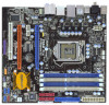
SPEAKER 1, Purple) 5 1156-Pin CPU Socket 22 Clear CMOS Jumper (CLRCMOS1) 6 2 x 240-pin DDR3 DIMM Slots 23 System PCI Express 2.0 x16 Slot (PCIE1, Blue) 14 Intel P55 Chipset 33 HDMI_SPDIF Header 15 16Mb SPI Flash (HDMI_SPDIF1, Yellow) 16 USB 2.0 Header (USB12_13, Blue) 34 Internal Audio - ASRock P55M Pro | Quick Installation Guide - Page 3
** 9 Front Speaker (Lime) 10 Microphone (Pink) 11 Powered eSATAII Audio Output Connection Audio Output Channels Front Speaker Rear Speaker Central / Bass Side Speaker (No. 9) (No. 6) (No. 7) (No. 5) 2 V -- -- -- 4 V V -- -- 6 V V V -- 8 V V V V 3 ASRock P55M Pro Motherboard - ASRock P55M Pro | Quick Installation Guide - Page 4
will find "VIA HD Audio Deck" tool on your system. Please follow below instructions according to the OS you install. For Windows® XP / XP 64-bit OS: Please click "VIA HD Audio Deck" icon , and either Multi-Streaming function or Side Speaker function. English 4 ASRock P55M Pro Motherboard - ASRock P55M Pro | Quick Installation Guide - Page 5
of this manual occur, the updated version will be available on ASRock website without further notice. You may find the latest VGA cards and CPU support lists on ASRock website as well. ASRock website http://www.asrock.com If you require technical support related to this motherboard, please visit - ASRock P55M Pro | Quick Installation Guide - Page 6
CoreTM i5 Processors in the LGA1156 Package - 4 + 1 Power Phase Design - Supports Intel® Turbo Boost Technology - Supports Hyper-Threading Technology (see CAUTION 1) - Supports Untied Overclocking Technology (see CAUTION 2) - Supports EM64T CPU - Intel® P55 - Dual Channel DDR3 Memory Technology (see - ASRock P55M Pro | Quick Installation Guide - Page 7
(Intelligent Overclocking Technology) - Supports Smart BIOS Support CD - Drivers, Utilities, AntiVirus Software (Trial Version) Unique Feature - ASRock OC Tuner (see CAUTION 9) - Intelligent Energy Saver (see CAUTION 10) - Instant Boot - ASRock Instant Flash (see CAUTION 11) - ASRock OC DNA - ASRock P55M Pro | Quick Installation Guide - Page 8
and Windows® VistaTM 64bit with 64-bit CPU, there is no such limitation. 5. For those CPU that only support up to DDR3 1333, the XMP DDR3 1600 is supported through overclocking. 6. For microphone input, this motherboard supports both stereo and mono modes. For audio output, this motherboard supports - ASRock P55M Pro | Quick Installation Guide - Page 9
Intelligent Energy Saver. ASRock website: http://www.asrock.com/feature/IES/index.html 11. ASRock Instant Flash is a BIOS flash utility embedded in Flash ROM. This convenient BIOS update tool allows you to update system BIOS without entering operating systems first like MS-DOS or Windows®. With this - ASRock P55M Pro | Quick Installation Guide - Page 10
with * mark are supported under Windows® VistaTM / VistaTM 64-bit only. * For the latest updates of the supported PCI Express VGA card list for CrossFireXTM Mode, please visit our website for details. ASRock website: http://www.asrock.com/support/index.htm English 10 ASRock P55M Pro Motherboard - ASRock P55M Pro | Quick Installation Guide - Page 11
Before you insert the 1156-Pin CPU into the socket, please check if the CPU surface is unclean or if there is any bent pin on the socket. Do not force to insert the CPU into the socket if above situation is found. Otherwise, the CPU will be seriously damaged. English 11 ASRock P55M Pro Motherboard - ASRock P55M Pro | Quick Installation Guide - Page 12
key notches. orientation key notch alignment key Pin1 Pin1 orientation key notch alignment key 1156-Pin Socket 1156-Pin CPU For proper inserting, please ensure to match the two orientation key notches of the CPU with the two alignment keys of the socket. 12 ASRock P55M Pro Motherboard - ASRock P55M Pro | Quick Installation Guide - Page 13
other components. et Please be noticed that this motherboard supports Combo Cooler Option (C.C.O.), which provides the flexible option to adopt two different CPU cooler types, Socket LGA 775 and LGA 1156. The white throughholes are for Socket LGA 1156 CPU fan. 13 ASRock P55M Pro Motherboard English - ASRock P55M Pro | Quick Installation Guide - Page 14
the Dual Channel Memory Technology. 3. It is not allowed to install a DDR or DDR2 memory module into DDR3 slot;otherwise, this motherboard and DIMM may be damaged. 4. Please install the memory module into the white slot (DDR3_B1) for the first priority. English 14 ASRock P55M Pro Motherboard - ASRock P55M Pro | Quick Installation Guide - Page 15
. It will cause permanent damage to the motherboard and the DIMM if you force the DIMM into the slot at incorrect orientation. Step 3. Firmly insert the DIMM into the slot until the retaining clips at both ends fully snap back in place and the DIMM is properly seated. 15 ASRock P55M Pro Motherboard - ASRock P55M Pro | Quick Installation Guide - Page 16
1 PCI slot and 3 PCI Express slots on this motherboard. PCI slot: PCI slot is used to install expansion cards that have the 32-bit PCI interface. PCIE slots: PCIE1 (PCIE x16 slot; Blue) is used for PCI Express x16 lane width graphics cards, or used to install PCI Express graphics cards to support - ASRock P55M Pro | Quick Installation Guide - Page 17
in the future, please refer to ATITM graphics card manuals for detailed installation guide. Step 1. Insert one Radeon graphics card into PCIE1 slot and the other Radeon graphics card to PCIE3 slot. Make sure that the cards are properly seated on the slots. 17 ASRock P55M Pro Motherboard English - ASRock P55M Pro | Quick Installation Guide - Page 18
2. Connect the DVI monitor cable to the DVI connector on the Radeon graphics card on PCIE1 slot. (You may use the DVI to D-Sub adapter to convert the DVI connector to D-Sub interface, and then connect the D-Sub monitor cable to the DVI to D-Sub adapter.) English 18 ASRock P55M Pro Motherboard - ASRock P55M Pro | Quick Installation Guide - Page 19
driver updates. Step 3. Step 4. Step 5. Install the required drivers to your system. For Windows® XP OS: A. ATITM recommends Windows® XP Service Pack 2 or higher to be installed (If you have Windows® XP Service on the Radeon graphics cards. Click "Apply". English 19 ASRock P55M Pro Motherboard - ASRock P55M Pro | Quick Installation Guide - Page 20
trademark of ATITM Technologies Inc., and is used only for identification or explanation and to the owners' benefit, without intent to infringe. * For further information of ATITM CrossFireXTM technology, please check AMD website for updates and details. 20 ASRock P55M Pro Motherboard English - ASRock P55M Pro | Quick Installation Guide - Page 21
CLRCMOS1 for 5 seconds. However, please do not clear the CMOS right after you update the BIOS. If you need to clear the CMOS when you just finish updating the BIOS, you must boot up the system first, and then shut it down before you do the clearCMOS action. English 21 ASRock P55M Pro Motherboard - ASRock P55M Pro | Quick Installation Guide - Page 22
black end of Power Cable SATA power cable to the power (Optional) connect to the SATA HDD power connector connector on each drive. Then connect the white end of SATA connect to the power cable to the power power supply connector of the power supply. 22 ASRock P55M Pro Motherboard English - ASRock P55M Pro | Quick Installation Guide - Page 23
store keys, digital certificates, passwords, and data. A TPM system also helps enhance network security, protects digital identities, and ensures platform integrity. This header supports an optional wireless transmitting and receiving infrared module. 23 ASRock P55M Pro Motherboard English - ASRock P55M Pro | Quick Installation Guide - Page 24
card, or MPEG card. This is an interface for front panel audio cable that allows convenient connection and control of audio devices. 1. High Definition Audio supports Jack Sensing, but the panel wire on the chassis must support HDA to function correctly. Please follow the instruction in our manual - ASRock P55M Pro | Quick Installation Guide - Page 25
. 17) 4-Pin ATX 12V Power Supply Installation 1 6 Besides one default IEEE 1394 port on the I/O panel, there is one IEEE 1394 header (FRONT_1394) on this motherboard. This IEEE 1394 header can support one IEEE 1394 port. 25 ASRock P55M Pro Motherboard - ASRock P55M Pro | Quick Installation Guide - Page 26
to this header. Please connect the black end (A) of HDMI_SPDIF cable to the HDMI_SPDIF header on the motherboard. Then connect the white end (B or C) of HDMI_SPDIF cable to the HDMI_SPDIF connector of HDMI VGA card. B. white end (2-pin) C. white end (3-pin) English 26 ASRock P55M Pro Motherboard - ASRock P55M Pro | Quick Installation Guide - Page 27
below steps. Using SATA / SATAII HDDs without NCQ function STEP 1: Set up BIOS. A. Enter BIOS SETUP UTILITY Advanced screen Storage Configuration. B. Set the option "SATAII Operation Mode" to [IDE]. STEP 2: Install Windows® XP / XP 64-bit OS on your system. 27 ASRock P55M Pro Motherboard English - ASRock P55M Pro | Quick Installation Guide - Page 28
the instruction to install Windows® VistaTM / VistaTM 64-bit OS on your system. When you see "Where do you want to install Windows?" page, please insert the ASRock Support CD into your optical drive, and click the "Load Driver" button on the left on the bottom to load the Intel® AHCI drivers. Intel - ASRock P55M Pro | Quick Installation Guide - Page 29
your computer. If the Main Menu does not appear automatically, locate and double-click on the file "ASSETUP. EXE" from the BIN folder in the Support CD to display the menus. 29 ASRock P55M Pro Motherboard English - ASRock P55M Pro | Quick Installation Guide - Page 30
ASRock P55M Pro Motherboard (Micro ATX-Formfaktor: 24.4 cm x 22.4 cm; 9.6 Zoll x 8.8 Zoll) ASRock P55M Pro Schnellinstallationsanleitung ASRock P55M Pro Support-CD Ein 80-adriges Ultra-ATA 66/100/133 IDE-Flachbandkabel Ein Flachbandkabel für ein 3,5-Zoll-Diskettenlaufwerk Zwei Serial ATA (SATA - ASRock P55M Pro | Quick Installation Guide - Page 31
x16-Steckplatz (im x4-Modus, 2,5 GT/s) - 1 x PCI Express 2.0 x1-Steckplatz (2,5 GT/s) - 1 x PCI -Steckplatz - Unterstützt ATITM CrossFireXTM und Quad CrossFireXTM - 7.1 CH Windows® VistaTM Premium Level HD Audio (VIA® VT1708S Audio Codec) - PCIE x1 Gigabit LAN 10/100/1000 Mb/s - Realtek RTL8111DL - ASRock P55M Pro | Quick Installation Guide - Page 32
Energy Saver (Intelligente Energiesparfunktion) (siehe VORSICHT 10) - Sofortstart - ASRock Instant Flash (siehe VORSICHT 11) - ASRock OC DNA (siehe VORSICHT 12) - Hybrid Booster: - Schrittloser CPU-Frequenz-Kontrolle (siehe VORSICHT 13) - ASRock U-COP (siehe VORSICHT 14) ASRock P55M Pro Motherboard - ASRock P55M Pro | Quick Installation Guide - Page 33
tatsächliche Speichergröße weniger als 4 GB betragen, da unter Windows® XP und Windows® Vista™ etwas Speicher zur Nutzung durch das System reserviert wird. Unter Windows® XP 64-bit und Windows® Vista™ 64-bit mit 64-Bit-CPU besteht diese Einschränkung nicht. 33 ASRock P55M Pro Motherboard Deutsch - ASRock P55M Pro | Quick Installation Guide - Page 34
der Name - OC DNA* - beschreibt es wörtlich, was die Software zu leisten vermag. OC DNA ist ein von ASRock exklusiv entwickeltes Dienstprogramm, das Nutzern eine bequeme Möglichkeit bietet, Übertaktungseinstellungen aufzuzeichnen und sie Anderen mitzuteilen. 34 ASRock P55M Pro Motherboard Deutsch - ASRock P55M Pro | Quick Installation Guide - Page 35
zwei verschiedenen CPU-Kühlertypen, Socket LGA 775 und LGA 1156. Beachten Sie bitte, dass nicht alle 775 CPU-Lüfter verwendet EuP-fähiges Motherboard und eine EuP-fähige Stromversorgung erforderlich. Gemäß einer Empfehlung von Intel muss eine EuP abzufragen. 35 ASRock P55M Pro Motherboard Deutsch - ASRock P55M Pro | Quick Installation Guide - Page 36
) 1156-Pin Sockel Übersicht Bevor Sie die 1156-Pin CPU in den Sockel sitzen, prüfen Sie bitte, ob die CPU-Oberfläche sauber ist und keine der Kontakte verbogen sind. Setzen Sie die CPU nicht mit Gewalt in den Sockel, dies kann die CPU schwer beschädigen. Deutsch 36 ASRock P55M Pro Motherboard - ASRock P55M Pro | Quick Installation Guide - Page 37
mit dem IHS (Integrated Heat Sink - integrierter Kühlkörper) nach oben. Suchen Sie Pin 1 und die zwei Orientierungseinkerbungen. Orientierungskerbe Ausrichtungsmarkierung Pin1 Orientierungskerbe 1156-Pin CPU Ausrichtungsmarkierung 1156-Pin Sockel ASRock P55M Pro Motherboard Pin1 37 Deutsch - ASRock P55M Pro | Quick Installation Guide - Page 38
. Schritt 3-3. Drücken Sie die CPU vorsichtig in vertikaler Richtung in den Sockel. Schritt 3-4. Prüfen Sie, dass die CPU ordnungsgemäß im Sockel sitzt und die Ladehebel. Schritt 4-3. Sichern Sie Ladehebel und Ladeplatte mithilfe des Hebelverschlusses. 38 ASRock P55M Pro Motherboard Deutsch - ASRock P55M Pro | Quick Installation Guide - Page 39
, dass dieses Motherboard die ComboKühleroption unterstützt, die eine flexible Möglichkeit zur Aufnahme von zwei verschiedenen CPU-Kühlertypen, Socket LGA 775 und LGA 1156, bietet. Das weiße Durchgangsloch ist für den CPULüfter im Socket LGA 1156 vorgesehen. 39 ASRock P55M Pro Motherboard Deutsch - ASRock P55M Pro | Quick Installation Guide - Page 40
nicht aktivieren. 3. Es ist nicht zulässig, DDR oder DDR2 in einen DDR3 Steckplatz zu installieren; andernfalls könnten Motherboard und DIMMs beschädigt werden. 4. Installieren Sie das Speichermodul für die erste Priorität im weißen Steckplatz (DDR3_B1). Deutsch 40 ASRock P55M Pro Motherboard - ASRock P55M Pro | Quick Installation Guide - Page 41
in die Steckplätze, so dass die Halteklammern an beiden Enden des Moduls einschnappen und das DIMM-Modul fest an Ort und Stelle sitzt. 41 ASRock P55M Pro Motherboard - ASRock P55M Pro | Quick Installation Guide - Page 42
und PCI Express-Steckplätze) Es gibt einen 1 PCI-Steckplätze und 3 PCI Express-Steckplätze am P55M Pro Motherboard. PCI-Slots: PCI-Slots werden zur Installation von Erweiterungskarten mit dem 32bit PCI-Interface genutzt. PCI Express-Slots: PCIE1 (PCIE x16-Steckplatz; blau) wird für PCI Express x16 - ASRock P55M Pro | Quick Installation Guide - Page 43
Display-Aufrüstung. Mit zusätzlichen PCI Express-VGA-Karte können Sie die Vorteile der Surround Display-Funktion problemlos genießen. Für detaillierte Informationen, siehe folgendes Dokument auf beiliegender Support-CD: ..\ Surround Display Information 43 ASRock P55M Pro Motherboard Deutsch - ASRock P55M Pro | Quick Installation Guide - Page 44
Sie nicht, den Jumper wieder zu entfernen, nachdem das CMOS gelöscht wurde. Wenn Sie den CMOS-Inhalt gleich nach dem Aktualisieren des BIOS löschen müssen, müssen Sie zuerst das System starten und dann wieder ausschalten, bevor Sie den CMOS-Inhalt löschen. Deutsch 44 ASRock P55M Pro Motherboard - ASRock P55M Pro | Quick Installation Guide - Page 45
. 10) (SATAII_3: siehe S.2 - No. 12) (SATAII_4: siehe S.2 - No. 13) Serial ATA- (SATA-) SATA Datenkabels kann an die SATA / SATAII Festplatte oder das SATAII Verbindungsstück auf dieser Hauptplatine angeschlossen werden. SATAII_4 SATAII_2 SATAII_3 SATAII_1 Deutsch 45 ASRock P55M Pro Motherboard - ASRock P55M Pro | Quick Installation Guide - Page 46
-HDD-Stromanschluss Verbindung zum Netzteil Verbinden Sie das schwarze Ende des SATA-Netzkabels mit dem Netzanschluss am Laufwerk. Verbinden Sie dann das weiße Ende des SATAStromversorgungskabels mit speichern lassen. Ein TPM-System hilft auch bei der Verbesserung der ASRock P55M Pro Motherboard - ASRock P55M Pro | Quick Installation Guide - Page 47
Kontrolle über Audio-Geräte. 1. High Definition Audio unterstützt Jack BIOS-Setup-Dienstprogramm auf. Wechseln Sie zu Erweiterte Einstellungen und wählen Sie Chipset-Konfiguration. Setzen Sie die Option Frontleistenkontrolle von [Automatisch] auf [Aktiviert]. Deutsch 47 ASRock P55M Pro Motherboard - ASRock P55M Pro | Quick Installation Guide - Page 48
angeschlossen werden; auch ohne Geschwindigkeitsregulierung. Wenn Sie einen dreipoligen CPU-Lüfter an den CPU-Lüferanschluss dieses Motherboards anschließen möchten, verbinden Sie ihn bitte mit Pin 13 ein. Installation eines 20-pol. ATX-Netzteils 1 13 48 ASRock P55M Pro Motherboard Deutsch - ASRock P55M Pro | Quick Installation Guide - Page 49
äten wie Fernsehgeräten, Projektoren, LCD-Geräten an das System. Bitte verbinden Sie den HDMI_SPDIF-Anschluss der HDMI-VGA-Karte mit diesem Anschluss. 49 ASRock P55M Pro Motherboard Deutsch - ASRock P55M Pro | Quick Installation Guide - Page 50
RAID-Funktionalität installieren Wenn Sie Windows® XP / XP 64-Bit / VistaTM / VistaTM 64-Bit ohne RAIDFunktionalität auf Ihren SATA / SATAII-Festplatten installieren, dann folgen Sie bitte je nach dem zu installierenden Betriebssystem den folgenden Schritten. Deutsch 50 ASRock P55M Pro Motherboard - ASRock P55M Pro | Quick Installation Guide - Page 51
bitte die ASRock Support CD in Ihr optisches Laufwerk ein. Klicken Sie anschließend die "Treiber laden"-Schaltfläche links unten, um die Intel® AHCI-Treiber zu installieren. Die Intel® AHCI-Treiber befinden sich in dem folgenden Verzeichnis auf der Support CD: 51 ASRock P55M Pro Motherboard Deutsch - ASRock P55M Pro | Quick Installation Guide - Page 52
der Support-CD, um die Menüs aufzurufen. Das Setup-Programm soll es Ihnen so leicht wie möglich machen. Es ist menügesteuert, d.h. Sie können in den verschiedenen Untermenüs Ihre Auswahl treffen und die Programme werden dann automatisch installiert. 52 ASRock P55M Pro Motherboard Deutsch - ASRock P55M Pro | Quick Installation Guide - Page 53
ères au modèle que vous utilisez. www.asrock.com/support/index.asp 1.1 Contenu du paquet Carte mère ASRock P55M Pro (Facteur de forme Micro ATX: 9.6 pouces x 8.8 pouces, 24.4 cm x 22.4 cm) Guide d'installation rapide ASRock P55M Pro CD de soutien ASRock P55M Pro Un câble ruban IDE Ultra ATA 66/100 - ASRock P55M Pro | Quick Installation Guide - Page 54
x4, 2,5GT/s) - 1 slot PCI Express 2.0 x1 (2,5GT/s) - 1 x slot PCI - Prend en charge ATITM CrossFireXTM et Quad CrossFireXTM - 7.1 Son haute définition de première qualité CH Windows® VistaTM (codec audio VIA® VT1708S) - PCIE x1 Gigabit LAN 10/100/1000 Mb/s - Realtek RTL8111DL - Support du Wake-On - ASRock P55M Pro | Quick Installation Guide - Page 55
Smart BIOS - Pilotes, utilitaires, logiciel anti-virus (Version d'essai) - Tuner ASRock OC (voir ATTENTION 9) - Économiseur d'énergie intelligent (voir ATTENTION 10) - l'Instant Boot - ASRock Instant Flash (voir ATTENTION 11) - ASRock OC DNA (voir ATTENTION 12) 55 ASRock P55M Pro Motherboard Fran - ASRock P55M Pro | Quick Installation Guide - Page 56
Du fait des limites du système d'exploitation, la taille mémoire réelle réservée au système pourra être inférieure à 4 Go sous Windows® XP et Windows® VistaTM. Avec Windows® XP 64 bits et Windows® VistaTM 64 bits avec CPU 64 bits, il n'y a pas ce genre de limitation. 56 ASRock P55M Pro Motherboard - ASRock P55M Pro | Quick Installation Guide - Page 57
entrar nos sistemas operativos, como o MS-DOS ou o Windows®. Com este utilitário, poderá premir a tecla durante o teste de arranque POST ou premir a tecla para exibir o menu de configuração do BIOS para aceder ao ASRock Instant Flash. Execute esta ferramenta para guardar o novo ficheiro de - ASRock P55M Pro | Quick Installation Guide - Page 58
refroidisseur sde CPU, les sockets LGA 775 et LGA 1156. Veuillez noter que tous les ventilateurs de CPU 775 ne mère EuP et une alimentation EuP sont requises. Selon les suggestions d'Intel', l'alimentation électrique EuP doit correspondre à la norme, qui est que ASRock P55M Pro Motherboard Français - ASRock P55M Pro | Quick Installation Guide - Page 59
dans le socket, veuillez vérifier que la surface du processeur est bien propre, et qu'il n'y a aucune broche tordue sur le socket. Si c'est le cas, ne forcez pas pour insérer le processeur dans le socket. Sinon, le processeur sera gravement endommagé. Français 59 ASRock P55M Pro Motherboard - ASRock P55M Pro | Quick Installation Guide - Page 60
mis en place si vous renvoyez la carte mère pour service après vente. Etape 3. Insérez le processeur 1156 broches : Etape 3-1. Tenez le processeur par ses bords là Détrompeur 60 Encoche d'orientation Processeur 1156 broches Détrompeur Socket 1156 broches ASRock P55M Pro Motherboard broche 1 - ASRock P55M Pro | Quick Installation Guide - Page 61
dissipateur thermique Pour une installation correcte, veuillez vous reporter aux manuels d'instructions de votre ventilateur de processeur et de votre dissipateur thermique. L' le matériau d'interface thermique au centre de IHS sur la surface du socket. 61 ASRock P55M Pro Motherboard Français - ASRock P55M Pro | Quick Installation Guide - Page 62
prend en charge l'option Combo Cooler Option (C.C.O.), qui offre un choix flexible pour adopter deux types différents de refroidisseurs de CPU, les sockets LGA 775 et LGA 1156. Les trous traversant blancs sont pour le ventilateur de CPU au socket LGA 1156. Français 62 ASRock P55M Pro Motherboard - ASRock P55M Pro | Quick Installation Guide - Page 63
la Technologie de Mémoire à Canal Double. 3. Il n'est pas permis d'installer de la DDR ou DDR2 sur le slot DDR3; la carte mère et les DIMM pourraient être endommagés. 4. Veuillez tout d'abord installer le module de mémoire dans la fente blanche (DDR3_B1). Français 63 ASRock P55M Pro Motherboard - ASRock P55M Pro | Quick Installation Guide - Page 64
jusqu'à ce que les clips de maintien situés aux deux extrémités se ferment complètement et que le module DIMM soit inséré correctement. 64 ASRock P55M Pro Motherboard - ASRock P55M Pro | Quick Installation Guide - Page 65
fermement jusqu'à l'insertion complète de la carte dans son emplacement. Etape 4. Fixez la carte sur le châssis à l'aide d'une vis. Français 65 ASRock P55M Pro Motherboard - ASRock P55M Pro | Quick Installation Guide - Page 66
PCI Express, vous pouvez facilement jouir des avantages de la caractéristique de l'affichage Surround. Pour les instructions détaillées, veuillez vous reporter au document qui se trouve sur le chemin suivant dans le CD d'assistance : ..\ Surround Display Information 66 ASRock P55M Pro Motherboard - ASRock P55M Pro | Quick Installation Guide - Page 67
de suite après avoir mis le BIOS à jour. Si vous avez besoin d'effacer la CMOS lorsque vous avez fini de mettre le BIOS à jour, vous devez d'abord initialiser le système, puis le mettre hors tension avant de procéder à l'opération d'effacement de la CMOS. Français 67 ASRock P55M Pro Motherboard - ASRock P55M Pro | Quick Installation Guide - Page 68
: Veuillez vous reporter aux instructions du fabricant de votre IDE (SATAII_2: voir p.2 No. 10) (SATAII_3: voir p.2 No SATA) (en option) Toute cote du cable de data SATA peut etre connecte au disque dur SATA / SATAII ou au connecteur SATAII sur la carte mere. Français 68 ASRock P55M Pro Motherboard - ASRock P55M Pro | Quick Installation Guide - Page 69
No. 16) (US10_11 br.9) (voir p.2 No. 18) Veuillez connecter l'extrémité noire du cordon d'alimentation SATA sur le connecteur d'alimentation sur chaque unité. Connectez ensuite l'extrémité blanche du cordon d'alimentation , des mots de passe et des données. Un système 69 ASRock P55M Pro Motherboard - ASRock P55M Pro | Quick Installation Guide - Page 70
suivre les instructions dans notre manuel et le manuel de châssis afin installer votre système. 2. Si vous utilisez le panneau audio AC'97, installez-le sur l'adaptateur audio du panneau avant permet d'utiliser plusieurs fonctions du panneau système frontal. Français 70 ASRock P55M Pro Motherboard - ASRock P55M Pro | Quick Installation Guide - Page 71
terre. ien que cette carte mère offre un support de (Ventilateur silencieux) ventilateur de CPU à 4 broches , le ventilateur de CPU à 3 broches peut bien fonctionner même sans Veuillez connecter une unité d'alimentation électrique ATX 12V sur ce connecteur. 71 ASRock P55M Pro Motherboard Français - ASRock P55M Pro | Quick Installation Guide - Page 72
IEEE1394 (FRONT_1394) sur cette carte mere. Le header de IEEE 1394 peut supporter un port de IEEE 1394. En-tête de port COM (COM1 br.9) (en option) C B A Connecteur HDMI_SPDIF, fournissant une sortie audio SPDIF vers la carte VGA HDMI, et permettant au système ASRock P55M Pro Motherboard Français - ASRock P55M Pro | Quick Installation Guide - Page 73
Configurez le BIOS. A. Accédez à BIOS SETUP UTILITY (Utilitaire de configuration BIOS) écran Avancé Configuration Storage. B. Réglez «SATAII Operation Mode « sur [IDE]. ETAPE 2 : Installez le système d'exploitation Windows® XP / XP 64 bits sur votre système. 73 ASRock P55M Pro Motherboard Français - ASRock P55M Pro | Quick Installation Guide - Page 74
I386 (Pour les utilisateurs de Windows® VistaTM) .. \ AMD64 (Pour les utilisateurs de Windows® VistaTM 64-bits) Ensuite, veuillez insérer le disque optique de Windows® VistaTM / VistaTM 64-bits dans le lecteur optique de nouveau pour continuer l'installation. 74 ASRock P55M Pro Motherboard Français - ASRock P55M Pro | Quick Installation Guide - Page 75
le BIOS, veuillez consulter le Guide de l'utilisateur (fichier PDF) dans le CD technique. 4. Informations sur le CD de support Cette carte mère supporte divers systèmes d'exploitation Microsoft® Windows®: XP et double-cliquez dessus pour afficher les menus. 75 ASRock P55M Pro Motherboard Français - ASRock P55M Pro | Quick Installation Guide - Page 76
installazione rapida ASRock P55M Pro CD di supporto ASRock P55M Pro Un cavo IDE 80-pin Ultra ATA 66/100/133 Un cavo per floppy drive a 1,44 Mb Due cavi dati Serial ATA (SATA) (opzionali) Un cavi di alimentazione HDD Serial ATA (SATA) (opzionali) Un I/O Shield 76 ASRock P55M Pro Motherboard Italiano - ASRock P55M Pro | Quick Installation Guide - Page 77
à x16) - 1 x Alloggio PCI Express 2.0 x16 (a modalità x4, 2,5GT/s) - 1 x Alloggio PCI Express 2.0 x1 (2,5GT/s) - 1 x Alloggio PCI - Supporto di ATITM CrossFireXTM e Quad CrossFireXTM - 7.1 Audio HD CH Windows® VistaTM Premium Level (VIA® VT1708S Audio Codec) - PCIE x1 Gigabit LAN 10/100/1000 Mb - ASRock P55M Pro | Quick Installation Guide - Page 78
intelligente dell'energia) (vedi ATTENZIONE 10) - Instant Boot - ASRock Instant Flash (vedi ATTENZIONE 11) - ASRock OC DNA (vedi ATTENZIONE 12) - Booster ibrido: - Stepless control per frequenza del processore (vedi ATTENZIONE 13) - ASRock U-COP (vedi ATTENZIONE 14) ASRock P55M Pro Motherboard - ASRock P55M Pro | Quick Installation Guide - Page 79
overclocking. 6. Questa scheda madre supporta l'ingresso stereo e mono per il microfono. Questa scheda madre supporta le modalità 2 canali, 4 canali, 6 canali e 8 canali per l'uscita audio. Controllare la tavola a pagina 3 per eseguire il collegamento appropriato. 79 ASRock P55M Pro Motherboard - ASRock P55M Pro | Quick Installation Guide - Page 80
. 13. Anche se questa motherboard offre il controllo stepless, non si consiglia di effettuare l'overclocking. Frequenze del bus del processore diverse da quelle raccomandate possono causare instabilità al sistema o danni al processore e alla scheda madre. 80 ASRock P55M Pro Motherboard Italiano - ASRock P55M Pro | Quick Installation Guide - Page 81
dispersori di calore CPU, Socket LGA 775 e LGA 1156. Notare che non possono essere usate tutte le ventole CPU 775. 16. e una scheda elettrica predisposti EuP. In base ai suggerimenti Intel l'alimentatore predisposto EuP deve soddisfare lo standard secondo cui l' ASRock P55M Pro Motherboard Italiano - ASRock P55M Pro | Quick Installation Guide - Page 82
inserire la CPU da 1156-Pin nel socket, verificare che la superficie della CPU sia pulita e che non ci siano pin piegati nel socket. Non forzare l'inserimento della CPU nel socket se ci sono pin piegati. In caso contrario la CPU potrebbe essere seriamente danneggiata. 82 ASRock P55M Pro Motherboard - ASRock P55M Pro | Quick Installation Guide - Page 83
Sink: dispersore di calore integrato) verso l'alto. Individuare il Pin1 ed i due dentelli chiave d'orientamento. Dente di orientamento Tacca di allineamento Pin1 Dente di orientamento CPU da 1156-Pin Tacca di allineamento Socket da 1156-Pin ASRock P55M Pro Motherboard Pin1 83 Italiano - ASRock P55M Pro | Quick Installation Guide - Page 84
di allineamento della CPU con le due tacche nel socket. Fase 3-3. Collocare con delicatezza la CPU sulla presa con un movimento puramente verticale. Fase 3-4. Verificare che la CPU sia all'interno della della linguetta di ritenzione della leva di carico. Italiano 84 ASRock P55M Pro Motherboard - ASRock P55M Pro | Quick Installation Guide - Page 85
Notare che questa scheda mare supporta l'opzione C.C.O. (Combo Cooler Option), che fornisce la flessibilità di impiegare due tipi diversi di dispersori di calore CPU, Socket LGA 775 e LGA 1156. I fori di colore bianco sono per la ventola CPU Socket LGA 1156. Italiano 85 ASRock P55M Pro Motherboard - ASRock P55M Pro | Quick Installation Guide - Page 86
la tecnologia Dual Channel Memory. 3. Non è consentito installare la DDR o DDR2 nello slot DDR3, altrimenti si possono danneggiare questa scheda madre e la DIMM. 4. Installare il modulo di memoria nell'alloggio bianco (DDR3_B1) per la prima priorità. Italiano 86 ASRock P55M Pro Motherboard - ASRock P55M Pro | Quick Installation Guide - Page 87
DIMM nello slot fino a far scattare completamente in posizione i fermagli di ritegno alle due estremità e fino ad installare correttamente la DIMM nella sua sede. 87 ASRock P55M Pro Motherboard - ASRock P55M Pro | Quick Installation Guide - Page 88
scheda con lo slot e premere con decisione finché la scheda è completamente inserita nello slot. Step 4. Agganciare la scheda allo chassis con le viti. Italiano 88 ASRock P55M Pro Motherboard - ASRock P55M Pro | Quick Installation Guide - Page 89
. Con la scheda integrativa PCI Express VGA, si possono sfruttare con facilità i benefici della funzione Surround Display. Per le istruzioni dettagliate, fare riferimento al documento nel seguente percorso sul CD di supporto: ..\ Surround Display Information 89 ASRock P55M Pro Motherboard Italiano - ASRock P55M Pro | Quick Installation Guide - Page 90
jumper. Non cancellare la CMOS subito dopo aver aggiornato il BIOS. Se è necessario cancellare la CMOS una volta completato l'aggiornamento del BIOS, è necessario riavviare prima il sistema, e poi spegnerlo prima di procedere alla cancellazione della CMOS. Italiano 90 ASRock P55M Pro Motherboard - ASRock P55M Pro | Quick Installation Guide - Page 91
Nr. 10) (SATAII_3 SATA al (Opzionale) Connettere all'ailmentazione dei dischi SATA Connettere al gruppo di alimentazione connettore di alimentazione del drive. Poi connettete l'estremità bianca del cavo di alimentazione SATA al connettore power dell'alimentatore. 91 ASRock P55M Pro Motherboard - ASRock P55M Pro | Quick Installation Guide - Page 92
di rete, protegge le identità digitali e garantisce l'integrità della piattaforma. Questo collettore supporta moduli ad infrarossi optional per la trasmissione e la ricezione senza fili. 92 ASRock P55M Pro Motherboard Italiano - ASRock P55M Pro | Quick Installation Guide - Page 93
manuale e del manuale del telaio per installare il sistema. 2. Se si utilizza un pannello audio AC'97, installarlo nell'intestazione audio audio HD. Non è necessario collegarli per il pannello audio AC'97. E. Entrare nel programma di impostazione BIOS. . Italiano 93 ASRock P55M Pro Motherboard - ASRock P55M Pro | Quick Installation Guide - Page 94
. Sebbene la presente scheda madre disponga di un supporto per ventola CPU a 4 piedini (ventola silenziosa), la ventola CPU a 3 piedini è in grado di funzionare anche senza la funzione 4 8 al Pin 1 e Pin 5. Installazione elettrica 4-Pin ATX 12V 1 6 94 ASRock P55M Pro Motherboard Italiano - ASRock P55M Pro | Quick Installation Guide - Page 95
Nr. 33) Cavo HDMI_SPDIF (opzionale) A. estremità nera Header HDMI_SPDIF, con uscita audio SPDIF su scheda HDMI VGA, consente al sistema di collegare dispositivi per TV digitale della scheda HDMI VGA. B. estremità bianca (2 pin) C. estremità bianca (3 pin) 95 ASRock P55M Pro Motherboard Italiano - ASRock P55M Pro | Quick Installation Guide - Page 96
Passo 1: Configurare il BIOS. A. Entrare in BIOS SETUP UTILITY (UTILITÀ DI CONFIGURAZIONE DEL BIOS) Advanced screen (Avanzate) Storage Configuration. B. Impostare "SATAII Operation Mode" su [IDE]. Passo 2: Installazione di Windows® XP / XP 64-bit sul sistema. 96 ASRock P55M Pro Motherboard Italiano - ASRock P55M Pro | Quick Installation Guide - Page 97
I driver Intel® AHCI si trova sul seguente percorso del CD di supporto: .. \ I386 (per utenti Windows® VistaTM) .. \ AMD64 (per utenti Windows® VistaTM 64-bit) Dopodiché, inserire di nuovo il disco Windows® VistaTM / VistaTM 64-bit nell'unità ottica per continuare l'installazione. 97 ASRock P55M Pro - ASRock P55M Pro | Quick Installation Guide - Page 98
BIOS, fare riferimento al Manuale dell'Utente (PDF file) contenuto nel cd di supporto. 4. Software di supporto e informazioni su CD Questa scheda madre supporta vari sistemi operativi Microsoft® Windows®: supporto e cliccare due volte per visualizzare i menù. 98 ASRock P55M Pro Motherboard Italiano - ASRock P55M Pro | Quick Installation Guide - Page 99
de ASRock P55M Pro Una cinta de datos IDE de conducción 80 Ultra ATA 66/100/133 Una cinta de datos para una unidad de disco de 3,5" Dos cables de datos Serial ATA (SATA) (Opcional) Una cables de alimentación HDD Serial ATA (SATA) (Opcional) Una protección I/O 99 ASRock P55M Pro Motherboard Espa - ASRock P55M Pro | Quick Installation Guide - Page 100
x16) - 1 x ranura PCI Express 2.0 x16 (en modo x4, 2,5 GT/s) - 1 x ranura PCI Express 2.0 x1 (2,5 GT/s) - 1 x ranura PCI - Compatible con ATITM CrossFireXTM y Quad CrossFireXTM - Sonido HD de Nivel Superior 7.1 Canales Windows® VistaTM (Códec de sonido VIA® VT1708S) - PCIE x1 Gigabit LAN 10/100/1000 - ASRock P55M Pro | Quick Installation Guide - Page 101
de ASRock OC (vea ATENCIÓN 9) - Administrador de energía inteligente (vea ATENCIÓN 10) - Instant Boot - ASRock Instant Flash (vea ATENCIÓN 11) - ASRock OC DNA (vea ATENCIÓN 12) - Amplificador Híbrido: - Stepless control de frecuencia de CPU (vea ATENCIÓN 13) ASRock P55M Pro Motherboard 101 - ASRock P55M Pro | Quick Installation Guide - Page 102
, incluido el ajuste del BIOS, aplicando la tecnología de Por favor consulte página 50 del Manual del Usuario en el soporte CD sobre Windows® XP y Windows® VistaTM. Para equipos con Windows® XP 64-bit y Windows® VistaTM 64-bit con CPU de 64-bit, no existe dicha limitación. ASRock P55M Pro Motherboard - ASRock P55M Pro | Quick Installation Guide - Page 103
utilidad desarrollada por ASRock, representa para el usuario una forma cómoda de grabar su configuración de OC y compartirla con otras personas. Esta utilidad le permitirá guardar sus registros de aceleración en el sistema operativo y simplificar el ASRock P55M Pro Motherboard 103 Español - ASRock P55M Pro | Quick Installation Guide - Page 104
CPU diferentes, correspondientes a los zócalos LGA 775 y LGA 1156. Recuerde que no es posible el uso de todos los ventiladores para CPU ón que cumplan con la directiva EuP. Según las directrices de Intel, una fuente de alimentación que cumpla con la directiva EuP debe ASRock P55M Pro Motherboard - ASRock P55M Pro | Quick Installation Guide - Page 105
CPU de 1156 agujas en el socket, compruebe que la superficie de la CPU se encuentra limpia y no hay ninguna aguja torcida en el socket. No introduzca la CPU en el socket por la fuerza si se produce la situación anterior. Si lo hace, puede producir daños graves en la CPU. ASRock P55M Pro Motherboard - ASRock P55M Pro | Quick Installation Guide - Page 106
(Integrated Heat Sink) mirando hacia arriba. Busque la aguja 1 y las dos muescas de orientación. Muesca de orientación Tecla de alineación aguja 1 106 Muesca de orientación CPU de 1156 agujas Tecla de alineación Socket de 1156 agujas ASRock P55M Pro Motherboard aguja 1 - ASRock P55M Pro | Quick Installation Guide - Page 107
de la CPU. A continuación se ofrece un ejemplo para ilustrar la instalación del disipador para la CPU de 1156 agujas. Paso 1. Aplique el material termal de interfaz en el centro del IHS de la superficie del socket. (Aplique el material termal de interfaz) ASRock P55M Pro Motherboard 107 Espa - ASRock P55M Pro | Quick Installation Guide - Page 108
combinada (C.C.O.), una opción flexible que puede adaptarse a dos tipos de disipador de CPU diferentes, correspondientes a los zócalos LGA 775 y LGA 1156. Los orificios perforados de color blanco están destinados al ventilador de CPU para zócalos LGA 1156. Español 108 ASRock P55M Pro Motherboard - ASRock P55M Pro | Quick Installation Guide - Page 109
. 3. No se permite instalar módulos DDR o DDR2 en la ranura DDR3; si lo hace, esta placa base y los módulos DIMM pueden resultar dañados. 4. Por favor, instale el módulo de memoria en la ranura blanca (DDR3_B1) para que se le asigne la máxima prioridad. Español ASRock P55M Pro Motherboard 109 - ASRock P55M Pro | Quick Installation Guide - Page 110
de la ranura hasta que los clips de sujeción de ambos lados queden completamente introducidos en su sitio y la DIMM se haya asentado apropiadamente. 110 ASRock P55M Pro Motherboard - ASRock P55M Pro | Quick Installation Guide - Page 111
utilizar. Paso 3. Encaje el conector de la tarjeta a la ranura. Empuje firmemente la tarjeta en la ranura. Paso 4. Asegure la tarjeta con tornillos. Español ASRock P55M Pro Motherboard 111 - ASRock P55M Pro | Quick Installation Guide - Page 112
actualización Surround Display . Con la tarjeta PCI Express VGA puede disfrutar fácilmente de la función Surround Display. Para obtener instrucciones detalladas, consulte el documento en la siguiente ruta del CD de soporte: ..\ Surround Display Information Español 112 ASRock P55M Pro Motherboard - ASRock P55M Pro | Quick Installation Guide - Page 113
acuérdase de quitar el jumper cap después de limpiar el COMS. Si necesita borrar la CMOS cuando acabe de finalizar la actualización de la BIOS, debe arrancar primero el sistema y, a continuación, apagarlo antes de realizar la acción de borrado de CMOS. Español ASRock P55M Pro Motherboard 113 - ASRock P55M Pro | Quick Installation Guide - Page 114
: vea p.2, N. 11) (SATAII_2: vea p.2, N. 10) (SATAII_3: vea p.2, N. 12) (SATAII_4: vea SATA) (Opcional) Cualquier extremo del cable de los datos de SATA puede ser conectado con el disco duro de SATA / SATAII o el conectador de SATAII en esta placa base. Español 114 ASRock P55M Pro Motherboard - ASRock P55M Pro | Quick Installation Guide - Page 115
18) Conecte el extremo negro del de cable de SATA al conector de energía de la unidad. A continuación, conecte el extremo blanco del cable de alimentación SATA a la conexión de alimentación de la fuente seguridad. Los sistemas TPM también mejoran la seguridad de ASRock P55M Pro Motherboard 115 - ASRock P55M Pro | Quick Installation Guide - Page 116
Audio. 1. El Audio de Alta Definición soporta la detección de conector, pero el cable de panel en el chasis debe soportar HDA para operar correctamente. Por favor, siga las instrucciones en nuestro manual y en el manual de configuración del BIOS Entre en Configuración ASRock P55M Pro Motherboard - ASRock P55M Pro | Quick Installation Guide - Page 117
la patilla de masa. Conector del ventilador de la CPU (4-pin CPU_FAN1) (vea p.2, N. 3) 1 2 3 4 Conecte el cable del ventilador de la CPU a este conector y haga coincidir el cable negro con . Instalación de una Fuente de Alimentación ATX de 20 Pins 1 13 ASRock P55M Pro Motherboard 117 Español - ASRock P55M Pro | Quick Installation Guide - Page 118
al sistema conectarse a dispositivos de TV Digital HDMI / proyectores / Dispositivos LCD. Conecte el conector HDMI_SPDIF de la tarjeta VGA HDMI a esta cabecera. Español 118 ASRock P55M Pro Motherboard - ASRock P55M Pro | Quick Installation Guide - Page 119
ón en función del sistema operativo que tenga instalado. 2.11.1 Instalación de Windows® XP / XP 64 bits sin funciones RAID Si desea instalar Windows® XP / 64 bits en sus discos duros SATA / SATAII sin funciones RAID, por favor siga los pasos siguientes. ASRock P55M Pro Motherboard 119 Español - ASRock P55M Pro | Quick Installation Guide - Page 120
de soporte: .. \ I386 (para usuarios de Windows® VistaTM) .. \ AMD64 (para usuarios de Windows® VistaTM 64 bits) A continuación, vuelva a insertar el disco óptico de Windows® VistaTM / VistaTM 64 bits en la unidad óptica para continuar con la instalación. Español 120 ASRock P55M Pro Motherboard - ASRock P55M Pro | Quick Installation Guide - Page 121
configurar la BIOS, por favor refiérase al Manual del Usuario (archivo PDF) contenido en el CD. 4.Información de Software Support CD Esta placa-base soporta diversos tipos de sistema operativo Windows®: XP archivo "ASSETUP.EXE" para iniciar la instalación. Español ASRock P55M Pro Motherboard 121 - ASRock P55M Pro | Quick Installation Guide - Page 122
144 ASRock P55M Pro Motherboard - ASRock P55M Pro | Quick Installation Guide - Page 123
® ® ® ® ® ® ® ASRock P55M Pro Motherboard 145 - ASRock P55M Pro | Quick Installation Guide - Page 124
146 ASRock P55M Pro Motherboard - ASRock P55M Pro | Quick Installation Guide - Page 125
® " " ® ® ® ® " " " " ASRock P55M Pro Motherboard 147 - ASRock P55M Pro | Quick Installation Guide - Page 126
® ® 148 ASRock P55M Pro Motherboard - ASRock P55M Pro | Quick Installation Guide - Page 127
ASRock P55M Pro Motherboard 149 - ASRock P55M Pro | Quick Installation Guide - Page 128
Pin1 Pin1 150 ASRock P55M Pro Motherboard - ASRock P55M Pro | Quick Installation Guide - Page 129
ASRock P55M Pro Motherboard 151 - ASRock P55M Pro | Quick Installation Guide - Page 130
- 152 ASRock P55M Pro Motherboard - ASRock P55M Pro | Quick Installation Guide - Page 131
ASRock P55M Pro Motherboard 153 - ASRock P55M Pro | Quick Installation Guide - Page 132
154 ASRock P55M Pro Motherboard - ASRock P55M Pro | Quick Installation Guide - Page 133
® ® ASRock P55M Pro Motherboard 155 - ASRock P55M Pro | Quick Installation Guide - Page 134
"" "" "" "" 156 ASRock P55M Pro Motherboard - ASRock P55M Pro | Quick Installation Guide - Page 135
SATAII_4 SATAII_2 ASRock P55M Pro Motherboard SATAII_3 SATAII_1 157 - ASRock P55M Pro | Quick Installation Guide - Page 136
158 CD1 ASRock P55M Pro Motherboard - ASRock P55M Pro | Quick Installation Guide - Page 137
1 2 3 4 ASRock P55M Pro Motherboard 159 - ASRock P55M Pro | Quick Installation Guide - Page 138
12 24 1 13 4 8 1 6 12 24 1 13 4 8 1 6 160 ASRock P55M Pro Motherboard - ASRock P55M Pro | Quick Installation Guide - Page 139
12 24 1 13 C B A 4 8 1 6 ® ® \ 161 ASRock P55M Pro Motherboard - ASRock P55M Pro | Quick Installation Guide - Page 140
® ® ® ® ® ® ® ® 162 ® ASRock P55M Pro Motherboard - ASRock P55M Pro | Quick Installation Guide - Page 141
® ® ® ® \ ® \ ® ® " " \\ " " ASRock P55M Pro Motherboard 163 - ASRock P55M Pro | Quick Installation Guide - Page 142
164 ASRock P55M Pro Motherboard - ASRock P55M Pro | Quick Installation Guide - Page 143
® ® ® ® ® ® ® ASRock P55M Pro Motherboard 165 - ASRock P55M Pro | Quick Installation Guide - Page 144
166 ASRock P55M Pro Motherboard - ASRock P55M Pro | Quick Installation Guide - Page 145
® ® ® " " ® ® ® ® ASRock P55M Pro Motherboard 167 - ASRock P55M Pro | Quick Installation Guide - Page 146
® ® TM TM ® ® - 168 ASRock P55M Pro Motherboard - ASRock P55M Pro | Quick Installation Guide - Page 147
ASRock P55M Pro Motherboard 169 - ASRock P55M Pro | Quick Installation Guide - Page 148
170 ASRock P55M Pro Motherboard - ASRock P55M Pro | Quick Installation Guide - Page 149
ASRock P55M Pro Motherboard 171 - ASRock P55M Pro | Quick Installation Guide - Page 150
172 ASRock P55M Pro Motherboard - ASRock P55M Pro | Quick Installation Guide - Page 151
ASRock P55M Pro Motherboard 173 - ASRock P55M Pro | Quick Installation Guide - Page 152
174 ASRock P55M Pro Motherboard - ASRock P55M Pro | Quick Installation Guide - Page 153
ASRock P55M Pro Motherboard 175 - ASRock P55M Pro | Quick Installation Guide - Page 154
® ® \ 176 ASRock P55M Pro Motherboard - ASRock P55M Pro | Quick Installation Guide - Page 155
ASRock P55M Pro Motherboard 177 - ASRock P55M Pro | Quick Installation Guide - Page 156
178 SATAII_4 SATAII_2 ASRock P55M Pro Motherboard SATAII_3 SATAII_1 - ASRock P55M Pro | Quick Installation Guide - Page 157
CD1 ASRock P55M Pro Motherboard 179 - ASRock P55M Pro | Quick Installation Guide - Page 158
180 ASRock P55M Pro Motherboard - ASRock P55M Pro | Quick Installation Guide - Page 159
1 2 3 4 12 24 1 13 4 8 1 6 12 24 1 13 4 8 1 6 ASRock P55M Pro Motherboard 181 - ASRock P55M Pro | Quick Installation Guide - Page 160
C B A \ 182 ® ® ASRock P55M Pro Motherboard - ASRock P55M Pro | Quick Installation Guide - Page 161
® ® ® ® ® ® ® ® ASRock P55M Pro Motherboard 183 - ASRock P55M Pro | Quick Installation Guide - Page 162
® ® ® ® ® \ ® \ ® ® 184 ASRock P55M Pro Motherboard - ASRock P55M Pro | Quick Installation Guide - Page 163
® ® TM TM ASRock P55M Pro Motherboard 185 - ASRock P55M Pro | Quick Installation Guide - Page 164
186 ASRock P55M Pro Motherboard - ASRock P55M Pro | Quick Installation Guide - Page 165
® ® ® ® ® ® ® ASRock P55M Pro Motherboard 187 - ASRock P55M Pro | Quick Installation Guide - Page 166
188 ASRock P55M Pro Motherboard - ASRock P55M Pro | Quick Installation Guide - Page 167
® ® ® ® ® ® ® ® ASRock P55M Pro Motherboard 189 - ASRock P55M Pro | Quick Installation Guide - Page 168
® ® 190 ASRock P55M Pro Motherboard - ASRock P55M Pro | Quick Installation Guide - Page 169
ASRock P55M Pro Motherboard 191 - ASRock P55M Pro | Quick Installation Guide - Page 170
192 ASRock P55M Pro Motherboard - ASRock P55M Pro | Quick Installation Guide - Page 171
ASRock P55M Pro Motherboard 193 - ASRock P55M Pro | Quick Installation Guide - Page 172
- ASRock P55M Pro | Quick Installation Guide - Page 173
194 ASRock P55M Pro Motherboard - ASRock P55M Pro | Quick Installation Guide - Page 174
ASRock P55M Pro Motherboard 195 - ASRock P55M Pro | Quick Installation Guide - Page 175
196 ASRock P55M Pro Motherboard - ASRock P55M Pro | Quick Installation Guide - Page 176
® ® ® ASRock P55M Pro Motherboard 197 - ASRock P55M Pro | Quick Installation Guide - Page 177
198 ASRock P55M Pro Motherboard - ASRock P55M Pro | Quick Installation Guide - Page 178
SATAII_4 SATAII_2 SATAII_3 SATAII_1 ASRock P55M Pro Motherboard 199 - ASRock P55M Pro | Quick Installation Guide - Page 179
CD1 200 ASRock P55M Pro Motherboard - ASRock P55M Pro | Quick Installation Guide - Page 180
1 2 3 4 12 24 1 13 12 24 1 13 ASRock P55M Pro Motherboard 201 - ASRock P55M Pro | Quick Installation Guide - Page 181
4 8 1 6 4 8 1 6 C B A 202 ASRock P55M Pro Motherboard - ASRock P55M Pro | Quick Installation Guide - Page 182
4 8 1 6 ® ® ® ® ® ® ® ® ® ® ® ® ® ® ASRock P55M Pro Motherboard 203 - ASRock P55M Pro | Quick Installation Guide - Page 183
® ® ® ® ® ® ® ® ® ® ® ® ® ® ® 204 ASRock P55M Pro Motherboard - ASRock P55M Pro | Quick Installation Guide - Page 184
® ® ASRock P55M Pro Motherboard 205 - ASRock P55M Pro | Quick Installation Guide - Page 185
X O O O X O O O O: X: O O O O 206 ASRock P55M Pro Motherboard - ASRock P55M Pro | Quick Installation Guide - Page 186
O O ASRock P55M Pro Motherboard 207 - ASRock P55M Pro | Quick Installation Guide - Page 187
® ® ® ® ® ® ® 208 ASRock P55M Pro Motherboard - ASRock P55M Pro | Quick Installation Guide - Page 188
ASRock P55M Pro Motherboard 209 - ASRock P55M Pro | Quick Installation Guide - Page 189
® ® ® ® ® ® 210 ® ® ASRock P55M Pro Motherboard - ASRock P55M Pro | Quick Installation Guide - Page 190
® ® ASRock P55M Pro Motherboard 211 - ASRock P55M Pro | Quick Installation Guide - Page 191
212 ASRock P55M Pro Motherboard - ASRock P55M Pro | Quick Installation Guide - Page 192
ASRock P55M Pro Motherboard 213 - ASRock P55M Pro | Quick Installation Guide - Page 193
214 ASRock P55M Pro Motherboard - ASRock P55M Pro | Quick Installation Guide - Page 194
ASRock P55M Pro Motherboard 215 - ASRock P55M Pro | Quick Installation Guide - Page 195
216 ASRock P55M Pro Motherboard - ASRock P55M Pro | Quick Installation Guide - Page 196
ASRock P55M Pro Motherboard 217 - ASRock P55M Pro | Quick Installation Guide - Page 197
® ® ® 218 ASRock P55M Pro Motherboard - ASRock P55M Pro | Quick Installation Guide - Page 198
ASRock P55M Pro Motherboard 219 - ASRock P55M Pro | Quick Installation Guide - Page 199
220 SATAII_4 SATAII_2 SATAII_3 SATAII_1 ASRock P55M Pro Motherboard - ASRock P55M Pro | Quick Installation Guide - Page 200
CD1 ASRock P55M Pro Motherboard 221 - ASRock P55M Pro | Quick Installation Guide - Page 201
1 2 3 4 222 12 24 1 13 12 24 1 13 ASRock P55M Pro Motherboard - ASRock P55M Pro | Quick Installation Guide - Page 202
4 8 1 6 4 8 1 6 12 24 1 13 C B A ASRock P55M Pro Motherboard 223 - ASRock P55M Pro | Quick Installation Guide - Page 203
® ® ® ® ® ® ® ® ® ® ® ® ® ® 224 ASRock P55M Pro Motherboard - ASRock P55M Pro | Quick Installation Guide - Page 204
® ® ® ® ® ® ® ® ® ® ® ® ® ® ® ASRock P55M Pro Motherboard 225 - ASRock P55M Pro | Quick Installation Guide - Page 205
® ® ® 226 ASRock P55M Pro Motherboard
-
 1
1 -
 2
2 -
 3
3 -
 4
4 -
 5
5 -
 6
6 -
 7
7 -
8
-
9
-
10
-
11
-
12
-
13
-
14
-
15
-
16
-
17
-
18
-
19
-
20
-
21
-
22
-
23
-
24
-
25
-
26
-
27
-
28
-
29
-
30
-
31
-
32
-
33
-
34
-
35
-
36
-
37
-
38
-
39
-
40
-
41
-
42
-
43
-
44
-
45
-
46
-
47
-
48
-
49
-
50
-
51
-
52
-
53
-
54
-
55
-
56
-
57
-
58
-
59
-
60
-
61
-
62
-
63
-
64
-
65
-
66
-
67
-
68
-
69
-
70
-
71
-
72
-
73
-
74
-
75
-
76
-
77
-
78
-
79
-
80
-
81
-
82
-
83
-
84
-
85
-
86
-
87
-
88
-
89
-
90
-
91
-
92
-
93
-
94
-
95
-
96
-
97
-
98
-
99
-
100
-
101
-
102
-
103
-
104
-
105
-
106
-
107
-
108
-
109
-
110
-
111
-
112
-
113
-
114
-
115
-
116
-
117
-
118
-
119
-
120
-
121
-
122
-
123
-
124
-
125
-
126
-
127
-
128
-
129
-
130
-
131
-
132
-
133
-
134
-
135
-
136
-
137
-
138
-
139
-
140
-
141
-
142
-
143
-
144
-
145
-
146
-
147
-
148
-
149
-
150
-
151
-
152
-
153
-
154
-
155
-
156
-
157
-
158
-
159
-
160
-
161
-
162
-
163
-
164
-
165
-
166
-
167
-
168
-
169
-
170
-
171
-
172
-
173
-
174
-
175
-
176
-
177
-
178
-
179
-
180
-
181
-
182
-
183
-
184
-
185
-
186
-
187
-
188
-
189
-
190
-
191
-
192
-
193
-
194
-
195
-
196
-
197
-
198
-
199
-
200
-
201
-
202
-
203
-
204
-
205
 |
 |
1
ASRock
P55M Pro
Motherboard
English
English
English
English
English
Copyright Notice:
Copyright Notice:
Copyright Notice:
Copyright Notice:
Copyright Notice:
No part of this installation guide may be reproduced, transcribed, transmitted, or trans-
lated in any language, in any form or by any means, except duplication of documen-
tation by the purchaser for backup purpose, without written consent of ASRock Inc.
Products and corporate names appearing in this guide may or may not be registered
trademarks or copyrights of their respective companies, and are used only for identifica-
tion or explanation and to the owners’ benefit, without intent to infringe.
Disclaimer:
Disclaimer:
Disclaimer:
Disclaimer:
Disclaimer:
Specifications and information contained in this guide are furnished for informational
use only and subject to change without notice, and should not be constructed as a
commitment by ASRock. ASRock assumes no responsibility for any errors or omissions
that may appear in this guide.
With respect to the contents of this guide, ASRock does not provide warranty of any kind,
either expressed or implied, including but not limited to the implied warranties or
conditions of merchantability or fitness for a particular purpose. In no event shall
ASRock, its directors, officers, employees, or agents be liable for any indirect, special,
incidental, or consequential damages (including damages for loss of profits, loss of
business, loss of data, interruption of business and the like), even if ASRock has been
advised of the possibility of such damages arising from any defect or error in the guide
or product.
This device complies with Part 15 of the FCC Rules. Operation is subject to the
following two conditions:
(1)
this device may not cause harmful interference, and
(2)
this device must accept any interference received, including interference that
may cause undesired operation.
CALIFORNIA, USA ONLY
The Lithium battery adopted on this motherboard contains Perchlorate, a toxic
substance controlled in Perchlorate Best Management Practices (BMP) regulations
passed by the California Legislature. When you discard the Lithium battery in
California, USA, please follow the related regulations in advance.
“Perchlorate Material-special handling may apply, see
www
.dtsc.ca.gov/hazardouswa
ste/perchlorate”
ASRock Website: http://www.asrock.com
Published August 2009
Copyright
©
2009 ASRock INC. All rights reserved.